Ricardo Filipe Rodrigues Ferreira
Licenciado em Ciências da Engenharia Eletrotécnica e de Computadores
Cognitive Notification System for Door Lock
Dissertação para obtenção do Grau de Mestre em Engenharia Eletrotécnica e de Computadores
Orientador: Rui Manuel Leitão Santos-Tavares, Professor Auxiliar, Universidade Nova de Lisboa
Cognitive Notification System for Door Lock
Copyright © Ricardo Filipe Rodrigues Ferreira, Faculdade de Ciências e Tecnologia, Uni-versidade NOVA de Lisboa.
A Faculdade de Ciências e Tecnologia e a Universidade NOVA de Lisboa têm o direito, perpétuo e sem limites geográficos, de arquivar e publicar esta dissertação através de exemplares impressos reproduzidos em papel ou de forma digital, ou por qualquer outro meio conhecido ou que venha a ser inventado, e de a divulgar através de repositórios científicos e de admitir a sua cópia e distribuição com objetivos educacionais ou de inves-tigação, não comerciais, desde que seja dado crédito ao autor e editor.
Este documento foi gerado utilizando o processador (pdf)LATEX, com base no template “novathesis” [1] desenvolvido no Dep. Informática da FCT-NOVA [2].
Ac k n o w l e d g e m e n t s
Obrigado Faculdade de Ciências e Tecnologia da Universidade Nova de Lisboa. Obrigado por me teres acolhido por mais tempo do que o previsto, por me teres apresentado a algu-mas das pessoas mais importantes da minha vida e pelas experiências vividas naqueles que foram os melhores anos da minha vida. Até agora.
Agradeço ao Professor Rui Tavares pelo apoio no desenvolvimento deste trabalho, que fez com que pudesse condensar algumas das competências adquiridas ao longo do curso num projeto de grande interesse pessoal.
Obrigado aos meus pais, Isabel e Manuel, pela paciência, pelo apoio incondicional e por tudo o que me ensinaram, e continuam a ensinar, e que me ajudou a tornar na pessoa que hoje sou. Agradeço-vos do fundo do meu coração.
Ao que será sempre o meu mano mais velho, Gonçalo, obrigado pelos sábios conselhos e pela calma que me incutes sempre que tento dar passos maiores que as minhas pernas. Martim e Maria, obrigado pela ingenuidade e olhos brilhantes que me fazem voltar a ser criança. Que tenham em vocês todos os sonhos do Mundo.
Um obrigado também à restante família, com um especial beijinho para a minha Avó. Obrigado a todos os que fizeram parte desta caminhada académica com foco especial para o Flávio Jacinto, Francisco Silva, Gabriel Anacleto, Guilherme Góis, João Henriques, Miguel Santos, Pedro Alves, Ricardo Fortuna e Rui Batista. Sem vocês, teria sido muito mais difícil.
Obrigado aos parceiros da 3.5, Andreia Ribeiro, João Duarte, João Simões, Miguel Lopes, Pedro Lopes e Rodrigo Francisco. Sem vocês, teria sido menos divertido.
Obrigado também ao João Pombas e João Veloso por todos os conselhos técnicos ao longo do desenvolvimento deste trabalho. Sem vocês, teria aprendido muito menos.
Obrigado Diogo Santos, João Batista, Jorge Dias, Marta Meirinhos, Micael Fernan-des, Pedro Nunes, Rafaela Reis, Raquel Lourenço, Rodrigo Santos e Sara Martins pelas aventuras, experiências e irresponsabilidades.
Não queria deixar de agradecer ao Paulo Gonçalves e ao Thiago Marques pelos bons conselhos e conversas produtivas.
Obrigado ao Agrupamento de Escuteiros 895 de São João da Talha, pelo crescimento, experiências e amizades para a vida.
Obrigado ao Almada Communication Leaders Toastmasters Club pelo espírito de grupo e crescimento sustentado.
Obrigado à OLX, à Spark Agency e à Vodafone, pelas oportunidades de crescimento pessoal e profissional que me deram ao longo do meu percurso académico.
Por último, um agradecimento especial à Lúcia. Obrigado pelo apoio constante ao longo destes últimos anos e por me tornares uma pessoa melhor todos os dias. Esta meta também é tua, muitas mais virão.
Que as próximas aventuras e desafios continuem a ser partilhadas com todos vocês. Ricardo
A b s t r a c t
Most of the time, home automation devices provide peace of mind to their users by helping them in managing their house’s heat system, their garden watering or even controlling their home’s security. All the home automation devices connect to a network and they gather massive quantities of data that, most of the time, is underappreciated and only used to notify the users about real-time events.
Smart locks provide easy access to buildings and, like other home automation devices, generates a lot of rich data that can be used, and studied, to provide interesting features to their users.
This work proposes a smart lock cognitive notifications system that studies the smart lock activity generated data to provide notifications regarding the user’s behavior to the system administrator through a smartphone application.
The developed system comprises a cloud computing component that is responsible for the communications between all the system’s modules, data storage and ultimately it runs the cognitive notification system. To generate the needed data for the notifications system a smart lock prototype was also developed. The users can control the smart lock by using a smartphone application that includes several useful features.
The whole system works reliably and can be a good addition to the home automation market by enabling new possible features that will make the users lives more comfortable. Keywords: Internet of Things, Home Automation, Smart Lock System, Cognitive Notifi-cations System, Cloud Computing, Smartphone Application
R e s u m o
Na maioria das vezes, os dispositivos de automação residencial ajudam os seus utiliza-dores a atingir uma maior paz de espirito através do controlo automático do seu sistema de aquecimento, da rega do seu jardim ou no controlo do sistema de segurança. Todos os dispositivos de automação residencial podem estar ligados em rede e com isso juntar uma quantidade assinalável de dados que, na maioria das vezes, é subaproveitada e acaba apenas por ser utilizada para notificações de eventos em tempo real.
As fechaduras inteligentes fornecem acesso fácil a edifícios e, tal como outros dis-positivos de automação residencial, geram grandes quantidades de dados que podem ser usadas, e estudadas, para criar novas e interessantes funcionalidades para os seus utilizadores.
Este trabalho propõe um sistema cognitivo de notificações que estuda os dados gera-dos pela atividade de uma fechadura inteligente e que providencia notificações ao admi-nistrador do sistema, através de uma aplicação móvel, baseadas nos comportamentos dos utilizadores.
O sistema desenvolvido compreende uma componente de computação na nuvem que é responsável por todas as comunicações entre os módulos do sistema, pelo armazena-mento de dados e é onde o algoritmo do sistema cognitivo de notificações efetua as suas rotinas. Com o objetivo de gerar os dados necessários às notificações, foi desenvolvido um protótipo de uma fechadura inteligente. Os utilizadores deste sistema podem controlar a fechadura inteligente através de uma aplicação móvel desenvolvida para esse efeito e que inclui várias funcionalidades úteis.
O sistema funciona de modo sólido e pode ser uma boa adição ao mercado da automa-ção residencial podendo habilitar outros sistemas de novas funcionalidades que tornarão as vidas dos seus utilizadores mais confortáveis.
Palavras-chave: Internet das Coisas, Automação Residencial, Sistema de Fechadura Inte-ligente, Sistema de Notificações Cognitivas, Computação na Nuvem, Aplicação Móvel
C o n t e n t s
List of Figures xv
List of Tables xvii
Acronyms xix
1 Introduction 1
1.1 Motivation . . . 1
1.2 Objectives . . . 2
1.3 Document overview . . . 3
2 State of the Art 5 2.1 Smart lock market overview . . . 5
2.1.1 Nuki . . . 5
2.1.2 August . . . 8
2.2 Technology review . . . 10
2.2.1 Wireless communication protocols . . . 10
2.2.2 Cloud platforms . . . 13
2.2.3 Sensors and actuators . . . 14
2.2.4 Microcontrollers with wireless communications . . . 16
3 System Modeling 17 3.1 Use cases . . . 18 3.1.1 Cognitive notifications . . . 20 3.1.2 Cloud . . . 21 3.1.3 Hardware . . . 21 3.1.4 User/Smartphone Application . . . 22 3.2 System model . . . 23 3.3 System functions . . . 26
3.3.1 Cognitive notifications function . . . 26
3.3.2 Register function . . . 27
3.3.3 Login function . . . 28
C O N T E N T S
3.3.5 Edit user profile data function . . . 30
3.3.6 Activity log function . . . 31
3.3.7 Unlock function . . . 32
3.3.8 Smart lock hardware . . . 34
3.4 Data model . . . 36
4 System Implementation 39 4.1 Cloud . . . 39
4.1.1 Cognitive notifications system . . . 40
4.1.2 Cloud Database . . . 42
4.1.3 System requests and communication . . . 44
4.1.4 Security . . . 46
4.2 Smart lock hardware . . . 47
4.3 Smartphone application . . . 50
4.3.1 Login . . . 50
4.3.2 Register . . . 51
4.3.3 Logout . . . 52
4.3.4 User profile functionality . . . 53
4.3.5 Activity log functionality . . . 54
4.3.6 Unlock . . . 55 5 Conclusions 57 5.1 Results discussion . . . 57 5.2 Future work . . . 58 Bibliography 61 xiv
L i s t o f F i g u r e s
2.1 Example of a message sent through Bluetooth from Nuki smartphone
appli-cation to Nuki Smart lock, taken from [8]. . . 6
2.2 Example of a message sent through the internet from Nuki smartphone appli-cation to Nuki Smart lock, taken from [8]. . . 7
3.1 System prototype diagram . . . 18
3.2 Main use cases for each system module . . . 19
3.3 System’s cloud with focus in the Cognitive Notification System and database interactions . . . 20
3.4 Cloud communications diagram . . . 21
3.5 Smart lock hardware communications diagram . . . 22
3.6 Smartphone application communication with the cloud diagram . . . 22
3.7 Cognitive Notification System . . . 23
3.8 Register and login sequence diagram . . . 24
3.9 Check profile data sequence diagram . . . 24
3.10 Unlock action sequence diagram . . . 25
3.11 Check user activity sequence diagram . . . 25
3.12 Cognitive notification system sequence diagram . . . 26
3.13 Cognitive notifications function flowchart . . . 27
3.14 Register function flowchart . . . 28
3.15 Login function flowchart . . . 29
3.16 Logout function flowchart . . . 30
3.17 Edit user profile data function flowchart . . . 31
3.18 Activity log function flowchart . . . 32
3.19 Unlock function flowchart . . . 33
3.20 Smart lock hardware flowchart . . . 35
4.1 Cognitive notifications in the system administrator smartphone . . . 42
4.2 Database relational model . . . 43
4.3 OAuth 2.0 protocol flow taken from [37] . . . 47
4.4 PIR sensor signal output taken from [40] . . . 48
4.5 Smart lock hardware schematic . . . 50
L i s t o f F i g u r e s
4.7 Smartphone application user register screen . . . 52
4.8 Logout button in two different smartphone application screens . . . 53
4.9 Smartphone application Profile screen . . . 54
4.10 System administrator smartphone application Activity Log screen . . . 55
4.11 Smartphone application Your Lock screen . . . 56
L i s t o f Ta b l e s
2.1 Comparison of different wireless technologies, adapted from [13] . . . 12 4.1 Value assigned for each defined day period . . . 40
Ac r o n y m s
AES Advanced Encryption Standard. AWS Amazon Web Services.
BLE Bluetooth Low Energy. DC Direct Current.
GPIO General Purpose Input Output. HTTP Hyper Text Transfer Protocol.
HTTPS Hyper Text Transfer Protocol Secure. IDE Integrated Development Environment. IFTTT If This Then That.
IoT Internet of Things. LED Light-Emitting Diode. M2M Machine To Machine. NO Normally Open.
SQL Structured Query Language. UNB Ultra Narrow Band.
URL Uniform Resource Locator. USB Universal Serial Bus. UWB Ultra-Wideband.
AC R O N Y M S
WLAN Wireless Area Local Network. WPAN Wireless Personal Area Network. XML Extensible Markup Language.
C
h
a
p
t
e
r
1
I n t r o d u c t i o n
Technology is evolving every day. In most cases, technology improves the lives of others on a daily basis, making them easier or simply more productive.
Home automation is one branch of technology that has the aim to boost people’s lives just by automating processes that people have to manage each day in their homes. Simple processes like, opening or closing your blinds, managing the temperature of your heating system or controlling your home’s illumination can be automated according to users preferences and needs. This is the kind of technology that gives the users more time to put into really important things, making the users day more efficient and productive.
Home automation is divided into some areas. One of the most relevant is security, where we can find devices like smart locks, surveillance cameras, and smart alarm sys-tems. These devices are very relevant because they can give the users access to their homes, but since they’re smart devices that can be connected to the Web, they should be developed and designed properly to give real security to the product users.
1.1
Motivation
The Internet of Things (IoT) concept isn’t just the future, it’s already the present. Gartner forecasts said that in 2017, 8.4 billion things would be connected to the internet, which means a 31% expansion from the year before that. Their forecasts also predict that by 2020, those devices will reach the number of 20.4 billion, with an expected value of $2 trillion between devices/endpoints and services, [1].
In a near future, everything around us will be collecting, sending and receiving data for a lot of different purposes and goals.
Contributing to that massive growth and expansion is the home automation market. According to Mike Krell, who summed up the 2015 State of the Smart Home from iControl
C H A P T E R 1 . I N T R O D U C T I O N
Networks, users that are searching for home automation systems, are mainly looking for systems that don’t require any interaction, make their home more safe, energy efficient and that automate themselves as persons, [2][3].
The need for the security feeling is not new to humans, but the devices that provide it have made a long way to the ones in the present. The oldest lock system ever found was made of wood and supposedly belonged to the kingdom of Assyria. Egyptians and Romans upgraded it. By the 18th century, Joseph Bramah developed a system similar to today’s lock where the key lifted different heights in order to a corresponding pattern on the inside. In 1975, due to security problems in hotels, Tor Sornes developed and patented the first electronic keycard lock. Since then, the world has seen a massive evolution in the door lock systems, [4].
Smart locks will be definitely a big part of the Smart Home Market. Michael Wolf said, in the beginning of 2014, that were nearly 1 million homes in North America using some form of smart lock, while the predictions are for this market to hit $3.6 billion worldwide by 2019, [5].
Supporting all these innovations and emerging markets is the rates of adoption and usage of smartphones. Pew Research Center made a study which concludes that 95% of Americans own a cell phone of some kind, with 77% of these being smartphones, [6].This will surely have a great influence in the home automation market since most of the already available devices are controlled through smartphone applications making home automation solutions even more attractive to costumers.
With the IoT/Home Automation growth and expansion and with people looking for devices that can grant them more safety and automation in their lives, it’s very important that home automation devices, especially smart locks, can learn from their users habits providing them more value, automation, and functionality each day. This kind of very smart devices will make people more focused on the things that really matter in their lives while owning home automation devices that seem to be built for their own needs.
1.2
Objectives
This work aims to add a contribution to the home automation industry, especially to the smart lock market.
This work goal is to develop a smart lock cognitive notification system that can predict the smart lock users behaviors and give alerts to the system administrator in order for him to know if their kids reached home safely, if they already should be at home or if any different activity from the usual is happening. To properly develop the notification system an A to Z smart lock solution should be developed. That system should contain a simple smart lock prototype that is controlled through a smartphone application. A cloud platform must exist to control the system module’s interactions and to store all the generated data.
1 . 3 . D O C U M E N T O V E RV I E W
In order to contribute properly, a market approach should be made in order to assess the smart lock market needs and how can we develop a new solution that can complement the ones already on sale.
To develop a new solution it’s necessary to study the most recent technologies that can be used in our solution, their vantages, and disadvantages in order to reach the final goal.
The developed solution must be tested in order to correct the problems and bugs that may appear, this will make the final prototype more reliable.
1.3
Document overview
This document is structured in the following way:
• Chapter 2 reveals the State of the Art of IoT and Home Automation market and technology. The chapter is focused on doing an assessment of the smart locks market in order to evaluate the features and the operation of several smart locks that have already hit the shelves. The focus is also on the technology present in the IoT and Home Automation devices in the form of an overview of several technologies; • Chapter 3 describes succinctly a proposed solution, it’s functionalities and how the
system should behave;
• Chapter 4 provides an inside view of how the system was implemented and the technologies that were used to make it happen;
C
h
a
p
t
e
r
2
S ta t e o f t h e A rt
Home automation market is booming. At the same time, new products are launched, with a growing frequency, into the market with the aim to suppress all the user’s needs, or even to create new ones.
In this chapter, it’s presented a smart lock market approach of two of the most recent smart lock solutions that are supporting the market growth. The goal is to assess what has already been done and which value is this work providing to the market. The presented solutions define the benchmark for both the European and North American smart lock markets because of their high security standards, quantity and quality of features, such as auto-unlock and remote unlocking, and also by showing a great user experience through their smartphone applications.
2.1
Smart lock market overview
The presented solutions are some of the best in the developing smart lock market. Despite the fact that all of them provide their user’s great sets of useful features, none of them provides a notification system that is based on previously acquired knowledge like the one that is proposed by this work.
2.1.1 Nuki
Nuki Home Solutions is an Austrian company who aims to develop products that turn your home into a smart one. Their main product is Nuki Smart Lock, specially developed with the European market in mind. The Nuki Smart lock is fitted on the inside of your door, in the top of the key and it works by rotating it, [7].
Nuki provided their Smart Lock with Bluetooth Low Energy (BLE) in order to connect the smart lock to the smartphone application In order to use all the features available,
C H A P T E R 2 . S TAT E O F T H E A R T
Nuki Smart Lock must be connected to the web with Nuki Bridge that provides a Wi-Fi connection to the smart lock. Nuki Bridge is sold separately.
To use the smart lock, the user should have a smartphone with the Nuki smartphone application installed. There, the user can manage and configure his Nuki Smart Lock.
Nuki Smart Lock operations are powered by 4 AA batteries with an estimated battery life of 6 months, calculated with 8 locking processes per day. When the smart lock has only 20% battery left, the user receives a notification from the Nuki smartphone application suggesting the batteries replacement. If the smart lock batteries die, the user can continue to access his house using his physical keys. There’s another scenario to consider, the one where the user smartphone battery dies. In that case, there are several options to unlock the door. The user can use his physical keys, ask another authorized user to unlock it for him or use Nuki Fob, a small Bluetooth device that can connect to Nuki Smart Lock.
Security is one of the most important specifications for home automation products. Nuki provided their smart lock with BLE to communicate with the Nuki App, but instead of relying only on Bluetooth protocol security, they added an additional layer of security on top of it with end-to-end encryption, which means that only encrypted messages are sent and only the Nuki smartphone application and Nuki Smart lock know the key to decipher the message and perform the correspondent action as exemplified in figure 2.1.
Figure 2.1: Example of a message sent through Bluetooth from Nuki smartphone applica-tion to Nuki Smart lock, taken from [8].
Nuki guarantees that the same thing happens if you use Wi-Fi technology and Nuki Bridge to perform actions with your Nuki Smart Lock, with no data being saved on the Nuki servers, this action is exemplified in figure 2.2.
This smart lock can be improved by using another Nuki devices:
• Nuki Connect - This device adds web connection to the Nuki Smart Lock. It enables remote features like locking and unlocking the door and checking the state of the lock despite the user’s location;
• Nuki Fob - Small Bluetooth device that connects to the Nuki Smart Lock in order to lock/unlock it. Helps the user to access is house without a smartphone and physical keys;
2 . 1 . S M A R T L O C K M A R K E T O V E RV I E W
Figure 2.2: Example of a message sent through the internet from Nuki smartphone appli-cation to Nuki Smart lock, taken from [8].
• Nuki Box - This device aims to help the Nuki Smart Lock users that live in buildings, allowing them to control remotely the building’s door through the Nuki App. This smart lock has a very wide set of features available:
• Locking with the Smart Lock - With Nuki Smart Lock the user can lock or unlock the door by pressing the smart lock button. Alternatively, he can execute the same functions using the smart lock knob as if he would turn the mechanical key; • Locking with the Nuki App - Using the Nuki App, the user can lock and unlock
his smart lock with his smartphone, making it easier to enter and leave his house. With Nuki Bridge it’s possible to perform remote locking/unlocking;
• Lock ’n’ Go - This feature gives the user more comfort. With the push of a button the user can leave his house with the certainty that his door will lock automatically for him;
• Auto Unlock - This feature allows the user to unlock the door only by getting near it. It uses Global Positioning System, Bluetooth, and Geofences to help locate the user and sense when he’s near the door to connect the Nuki Smart Lock with the Nuki smartphone application and proceed with the unlock;
• Integration - Nuki Smart Lock has integration with Amazon’s Echo and Alexa and Google Home and Assistant, providing some voice commands that can control the smart lock. The smart lock has also IFTTT (If This Then That) integration, a free way to put apps and devices talking to each other, [9].
• Installation - Nuki Smart Lock is very easy to install since it doesn’t require any change to the regular lock in the door, which can be very useful for the average user who just wants to have a ready to use product on his hands, or in this case, on his door. Nuki Smart Lock is suitable for doors with handle or knob on the outside. The user can configure the smart lock to unlock the door or even to pull the latch, which means that it can open the door for him;
C H A P T E R 2 . S TAT E O F T H E A R T
• Nuki smartphone app - With the Nuki App, the administrator can control and manage every aspect of his Nuki Smart Lock. Using the application it’s possible to lock and unlock it, with Nuki Connect it can be done remotely. The application can also be used to check the lock activity log, see and manage the authorized users or invite new ones. The administrator is also able to invite temporary users by configuring a certain date and hour when that invite will be valid. An invited user receives an invitation code by text message or email and has to insert it into the Nuki smartphone application to gain access to the Smart Lock.
2.1.2 August
August, Inc is a company based in San Francisco, with focus on making locks more smart and helpful. Their high-end and main product is August Smart Lock Pro, which can connect to other secondary equipment’s that improve its mission of smartly unlocking doors. This smart lock should be installed on the inside of the door and is compatible with most deadbolt systems used in the United States of America houses, [10].
August equipped their main smart lock with three wireless communication protocols: Bluetooth, Wi-Fi and Z-Wave Plus. The lock has integration with Amazon’s Echo and Alexa, Google Home and Assistant, and Apple’s HomeKit and Siri, which enables a smart home where all devices are connected to a centralized hub where the user is able to control everything. The August Smart Lock Pro has also If This Then That (IFTTT) integration.
August Smart Lock Pro is powered by 4 AA batteries with an estimated battery life of 3 months. The user will receive two different warnings when his smart lock battery is low, he will receive a smartphone application (app) notification on his smartphone, and the smart lock will display a red flashing light. Although, if the smart lock batteries or even the user’s smartphone battery dies, the door lock it’s still usable with the physical key or even by logging into the user’s August account in a friend’s or neighbor phone.
The communication between the smartphone and the smart lock are always estab-lished via BLE. The packets exchanged between the two devices are used for the lock to authenticate the phone, grant or revoke user access and to update the smartphone application about who has locked/unlocked the lock. These packets are encrypted using Advanced Encryption Standard (AES) encryption, that is a symmetric encryption algo-rithm where both parties must send ciphertexts encrypted with the firmware key. But while the owner, or main user, has a unique key per session, where the smartphone has an offline key and only communicates with the lock to perform different actions, the guest user, or guest smartphone, does not have access to an offline key, so in order to interact with the lock, he has to communicate with the server which works as a middleman be-tween the guest smartphone and the smart lock. Without exploring more of the security protocols present in the August devices and app, it’s important to notice that in Fuller, Jenkins and Tjølsen security review, no major vulnerabilities were found in the device, [11].
2 . 1 . S M A R T L O C K M A R K E T O V E RV I E W
Regarding different user’s needs, August has very good additions to their smart lock. The user can update his smart lock with the following devices:
• August Smart Keypad - Exterior numerical keypad which enables the door unlock-ing action just by insertunlock-ing a numerical code;
• August Doorbell Cam Pro - It aims to replace the user’s existent doorbell. It has a camera built-in that connects to the application helping the user know who is at his front door. At the same time, he can see and speak with visitors using his phone; • August Connect - Provides web connection to the smart lock by connecting to
the user’s house Wi-Fi. Enables certain smart lock features that are only available through the Wi-Fi connection;
• DoorSense - This technology uses a magnetic field to determine if your door is closed or open. This device, that is placed near your smart lock, enhances the user experience.
August also incorporated several features in order to attend all their user’s necessities: • Locking with the Smart Lock - With August Smart Lock Pro, the user can unlock his door, from the inside of his house, just by rotating the smart lock just like using the door’s original deadlock;
• Locking with the August Home App - Using the August Home App, the user can lock and unlock his smart lock with his smartphone just by pressing a button. Re-mote locking/unlocking is available with August Connect device;
• Auto-Lock - With DoorSense sensor, the user can configure his smart lock to lock right after it’s closed, or after a configurable number of minutes. This feature also assures the re-lock of the door when the user unlocks it but don’t open it for some reason;
• Auto-Unlock - With Auto-Unlock feature, the smart lock knows and senses when the user and his smartphone are approaching the door and unlocks it without the user reaching his phone. The smart lock has two states, the Home Mode and Away Mode. When the lock is in Home Mode he is not looking for devices to get near, which prevents undesirable locking and unlocking actions. When the user leaves the neighborhood of his house, the lock enters in Away Mode, which means that the lock is now waiting for the user’s smartphone to enter in the house area to start the search in order to establish a connection with it and to execute the door unlocking for him;
• Remote monitoring and control - With the August Connect, the user is able to monitor and to control his door and smart lock states from remote locations;
C H A P T E R 2 . S TAT E O F T H E A R T
• Integration - August Smart Lock Pro has integration with several devices and ser-vices such as Amazon’s Echo and Alexa, Google Home and Assistant, and Apple’s HomeKit and Siri, which enables voice control over the smart lock. IFTTT integra-tion enables the smart lock to connect with other smart devices, like smart Light-Emitting Diode (LED) lights, and provides the creation of interactions and routines between those smart devices;
• Installation - Installing the August Smart Lock Pro is easy. The user can do it just by removing the inside of the door’s deadbolt and by fixing the smart lock there. The use of the physical keys remains available since there aren’t any changes on the outside lock hardware;
• August Home smartphone app - The August smartphone application is the main connection with their smart lock. There are two types of user, the Owner, and the Guest. The Owner can control and monitor everything that happens with the smart lock, locking and unlocking it (remotely or not), the lock and door state (locked, unlocked, open, closed, left ajar), activate/deactivate features, activity logs and invite/block guests. The Guest user can control the lock only by invite, it means that he has to be invited in order to use the lock. This invite can be a 24/7 one, or the Owner can define the day and hours that the invite will be valid for that specific guest. The smartphone application has also a smart alert function that sends notifications to the user reporting smart lock activity and smart lock and door states. Those notifications can be created by the user, but there’s no option to build the type notification as the one that is developed in this work.
2.2
Technology review
Internet of Things (IoT) and Home Automation devices rely on several technologies to work properly and seamlessly. In order to build a smart lock prototype, there is the need to review some of the most common technologies used in that kind of products, such as wireless communications, cloud platforms, sensors/actuators and . This review intends to be a general one, in order to select the most suitable and cheap technologies to apply in the smart lock prototype.
2.2.1 Wireless communication protocols
Wireless technologies have become very popular since they can reduce the costs of im-plementing automation in homes or other buildings by reducing the amount of cabling necessary to install devices like sensors. This kind of technologies also provides easiness associating smartphones with the automation system, as long as it can connect to the automation network, [12].
2 . 2 . T E C H N O L O G Y R E V I E W
In Home Automation there are several wireless communication protocols that can be used. The choice always depends on the devices, sensors, and actuators that are going to be connected and also on the features that the system is supposed to provide.
Considering the fact that this protocols of communication operate on an open medium, security has to be one of the concern when creating home automation solutions that make use of these protocols. Especially if those solutions are security-focused, like a door lock or an alarm system, since attackers can take over unsecured systems without even entering the building. As an additional issue, security features are limited by the requirement of low power consumption on the devices, meaning that a good relation security/power consumption has to be reached in order to reach the device/system requirements, such as price, power consumption among others.
This study [13] provides a general overview and comparison of four short-range wire-less communication protocols with low power consumption, Wi-Fi, Bluetooth, Ultra-Wideband (UWB) and ZigBee.
While Wi-Fi and UWB provide a high data rate, making them suitable for systems that need to send/receive a considerable amount of data, Bluetooth and ZigBee are intended for lower data rates. Wi-Fi is also designed to Wireless Area Local Network (WLAN), making it easier to provide a connection in a maximum 100m radius, while Bluetooth,
UWB, and ZigBee have been developed with Wireless Personal Area Network (WPAN) in mind providing a connection in a maximum 10m radius. In some applications, Zigbee
can also reach 100m range.
This study also approaches the different frequency bands used by the different wire-less communication protocols. Wi-Fi uses 2.4GHz or 5GHz, Bluetooth also uses the
2.4GHz frequency band, while UWB can use any frequency between 3.1GHz and 10.6GHz,
Zigbee can use frequency band between 868MHz and 915MHz or it can use the same
fre-quency as Bluetooth, 2.4GHz. This is an important parameter to evaluate since that radio
channels in the 2.4GHz band are unlicensed in most countries and is known as the
indus-trial, scientific and medical (ISM) band, however, it is excessively crowded. While high data rate applications have no other alternative, home automation applications can work by using lower frequencies, with the advantage of better wave propagation with the same amount of power spent, [12] [13] .
With Wi-Fi, Bluetooth and Zigbee sharing the same frequency band it’s important to notice that Bluetooth and UWB use adaptative frequency hopping in order to avoid channel collision with other protocols, while Zigbee and Wi-Fi use adaptative frequency selection that changes the frequency to another one where the protocol can operate.
All the four protocols have data encryption and authentication mechanisms as shown in table 2.1.
C H A P T E R 2 . S TAT E O F T H E A R T
Table 2.1: Comparison of different wireless technologies, adapted from [13]
Specification Communication Protocol
Wi-Fi Bluetooth Zigbee UWB Nominal Range [m] 100 10 10-100 10 Frequency Band [GHz] 2.4 or 5 2.4 0.868/0.915 or 2.4 3.1 - 10.6 Maximum Signal Rate [Mb/s] 54 1 0.250 110 Normalized Energy Consumption [mJ/Mb] Rx Tx Rx Tx Rx Tx Rx Tx <50 <50 100 - 150 100 - 150 300 - 350 250 - 300 <50 <50 Power Consumption [mW] Rx Tx Rx Tx Rx Tx Rx Tx 600 - 800 600 - 800 <200 <200 <200 <200 600 - 800 600 - 800 Encryption RC4 Stream cypher,
AES block cypher
E0 Stream cypher AES block cypher AES block cypher Authentication WPA2 Shared Secret CBC-MAC CBC-MAC
Shahzad and Bengt, compared ZigBee, Bluetooth Low Energy (BLE), and Wi-Fi for in-sensor processing versus raw data transmission. This study aims to check which one of those technologies is the most energy efficient one by checking the power consumption under different scenarios. The study concludes that for data load under 500 bytes ZigBee it’s the technology that spends the less amount of energy, on the other hand, Wi-Fi is best suited for data loads over 800kB while BLE it’s the best solution, of the three, for data loads between 500 bytes and 800kB, as is case for typical data-intensive monitoring applications, [14].
Sigfox was developed with the goal to offer a low-cost solution to connect all ma-chines and objects to the internet. It uses a patented Ultra Narrow Band (UNB) wireless communication technology and a cellular data transfer network optimized for Machine-to-Machine (M2M) and IoT applications like building automation, smart cities, asset tracking and others. Sigfox uses free frequency radio bands (license-free) to transmit data between a rate of 1b/s and 1kb/s, it can make transmissions in a 40km radius in open space and it only needs three base stations to cover a city with a million habitants. Sigfox company say they have the best price cellular communication service to M2M and IoT applications, [15]
This work aims to develop a simple smart lock prototype that can be controlled by a smartphone, at the same time there is the need to develop an online database in order to study the data generated by the smart lock usage and all the web communication to assure the integration of all the different modules. With this in mind, the most suitable technology to support the communications of the project is Wi-Fi. Wi-Fi communication protocol provides a reliable way to communicate with the device, that can easily connect to the web in order to receive requests from the cloud. Wi-Fi also enables the feature of locking and unlocking the smart lock from anywhere in the world if a web connection is available.
2 . 2 . T E C H N O L O G Y R E V I E W
2.2.2 Cloud platforms
In order to connect all the work modules, and also to store and study the data generated by the smart lock usage, there is the need to use a cloud solution for this work. The selected cloud platform will be the heart of all the system by managing all the smartphone application requests and all the interactions with the smart lock hardware itself.
To select the most suitable solution available we will need to evaluate the different specifications of each one, such as the offered storage capacity, how many GET and PUT data movements are available, and the overall price for using the service. It’s also neces-sary to consider the overall reach of the platform in order to not limit future works after this one.
Despite the high number of cloud solutions available, it’s necessary to consider the presented metrics in order to choose the right solution for this work.
• Amazon Web Services (AWS):
This Amazon service has specific products for IoT solutions with a big focus on IoT device management and data security. It has also an integrated data analytics service to help anyone to gather intelligence from their devices generated data. Every different product from Amazon has it’s own price, depending on which solu-tions the work will require. AWS products and services are available on a worldwide scale, [16].
• EasyIoT:
The EasyIoT cloud platform has the goal to provide a secure, reliable and cheap platform for IoT, mainly focused in Do It Yourself (DIY) products.
EasyIoT seems simple to use for the average user, but can’t provide as many services and functions as the big names on the market. It’s free to use unless the user wants to scale up its solution. It’s ideal for single users trying to deploy simple home automation in their own homes, [17].
• Google Cloud:
Google Cloud provides a worldwide cloud solution. Just like AWS, Google Cloud provides a wide range of products and services, including IoT solutions, such as Cloud IoT Core that provides secure device connection and management. Other products to compute and study data are also available.
Every different product from Google Cloud has it’s own price, depending on which solutions the work will require, [18].
• IBM Cloud:
Just like the other big names in the cloud platform industry, IBM has lots of services and products available on a worldwide scale.
C H A P T E R 2 . S TAT E O F T H E A R T
Internet of Things Platform, from IBM, helps to deploy and connect IoT solutions. Also, it has several data analysis functions where the user can define its own rules and trigger alerts and other functions.
Every different product from IBM Cloud has it’s own price, depending on which solutions the work will require, [19].
• Microsoft Azure:
Microsoft couldn’t step away from the cloud industry. It has a lot of services and products available including IoT focused solutions. Just like the competitors, Mi-crosoft has device management and data analytics build specifically to empower IoT solutions and devices.
Every different product from Microsoft Azure has it’s own price, depending on which solutions the work will require, [20].
2.2.3 Sensors and actuators
The door lock prototype that will be developed, will also rely on two sensors and one actuator. This work will need a sensing technology that allows the system to understand if the door is open or closed to avoid unnecessary lock/unlock actions, another sensor to assess movement/presence at the door to add a security layer in the unlock actions and an actuator that should perform the unlock actionper se.
• Door position or motion detection technologies
The door position or motion sensors will assess the state of the door, if it is opened or closed, in order to avoid unnecessary unlock/lock actions, such as locking the door while the door is open. It also develops an important role in registering new entry activities to the database whenever the door is unlocked and opened by a user. There are several sensing technologies that can be used to monitor objects position. To know a door position the cheapest and with more ease of assembling in a door are the accelerometer. The ADXL335 is a low power complete 3-axis accelerometer, it’s very small and has an operating voltage between 1.8 V and 3.6 V , [21]. Although the accelerometer has great qualities, it would be probably difficult to understand what’s the door positioning by measuring the acceleration of the door movements. Magnetic sensors are a very widely used technology in doors and windows. This type of sensors usually connects to the building alarm system to prevent burglars to enter. Two different technologies of magnetic sensors have been researched, the hall effect sensor and the reed switch sensor. There’s no big difference between them since they are both activated by an external magnetic influence. Despite that fact, reed switch sensor is known for being more stronger and robust than hall effect sensors, [22]. Also, there is some reed switch sensor that has been made with
2 . 2 . T E C H N O L O G Y R E V I E W
door and windows in mind [23] and that is already widely used in performing the functions that this system requires.
• Presence detection technologies
To add a security layer to the system this work will have a presence detection method. There are several presence detection technologies available, this review will highlight three of them.
– Ultrasonic sensors- Ultrasonic sensors are used to detect people and objects. It analyzes its surroundings by sending ultrasonic waves and to study how they are reflected back, this allows the sensor to detect motion. This type of sensor is usually used in home alarm systems. The main disadvantage of this type of sensing technology is that background noise and motion can sometimes trigger the sensor and perform a false alarm signal, [24].
– Microwave sensors- Microwave sensors uses electromagnetic radiation. Its functioning is similar to the ultrasonic sensor, it emits electromagnetic waves which are reflected back to the receiver. If an object or person motion is de-tected the receiver will identify changes in the electromagnetic waves. Mi-crowave detectors can go through walls and holes. Because of this, they can cover a larger area of a home, [25].
– Pyroelectric Infrared (PIR) sensors- PIR sensors are used to detect human bodies through infrared radiation. They are built to detect the infrared wave-length that human bodies emit. PIR sensors are low-cost, low-power and pro-vide a reliable indication of people presence [26]. This type of sensors doesn’t require any device or signal from a detecting object, unlike ultrasonic and mi-crowave sensors. Processing data from PIR sensors is much easier than from other motion sensing technologies, [27].
• Door lock rotation
The simplest method to simulate the door lock, or key lock, rotation, similar to the smart lock systems presented in section 2.1, is to attach a small DC servomotor to the chosen microcontroller.
This work’s focus is to create a cognitive notification system, so the chosen ser-vomotor will only simulate the door lock rotation since the prototype will not be assembled in a real door.
The DC servomotor has the function to rotate the key or other structure that shall be developed, in order to lock and unlock the door.
C H A P T E R 2 . S TAT E O F T H E A R T
2.2.4 Microcontrollers with wireless communications
To control and connect the sensors and actuator and also to receive/send data between the door lock prototype and the cloud platform this work needs a microcontroller that can give us all that.
To select the microcontroller from the ones available on the market, there is the need to define the specifications that are crucial to the development of this work, such as, number of General Purpose Input Output (GPIO) pins must be enough to support the magnetic sensor and the DC servomotor, it has to have enough voltage to supply the DC servomotor and, at the same time, it has to include, at least, the capability to connecting to other devices through Bluetooth, Wi-Fi or other wireless communication protocol. The pricing and ease of buying it are also relevant to the selection of the microcontroller.
Considering all the mentioned aspects, this section presents a comparison between some microcontrollers available in the market.
• ESP8266 Development Board (NodeMCU V1.0)
ESP8266 it’s a low power microcontroller focused on Wi-Fi connection. It has an operating voltage between 3.0V and 3.6V, with an operating current average value of 80mA. It has 10 GPIO pins to provide connection to other peripherals. It also has several different working modes in order to minimize the power consumption. In the deep sleep mode it has a typical power consumption of 10µA. This microcon-troller can be coded through Arduino IDE and also in Lua programming language, [28] [29].
• ESP32
ESP32 is a highly-integrated solution for Wi-Fi and Bluetooth IoT applications, since it has a Wi-Fi module and a Bluetooth module. It has an operation voltage between 2.3V and 3.6V. ESP32 includes 34 GPIO pins to connect the microcontroller to external sensors and actuators. Just like ESP8266 ESP12 E, it can provide a Deep Sleep mode in order to consume less power. In the deep sleep mode it has a typical power consumption of 10µA. This microcontroller can be coded through Arduino IDE and also in Lua programming language, [30].
• Bean LightBlue
The Bean LightBlue has embedded Bluetooth communication module, an accelerom-eter, a temperature sensor and an RGB LED. It works with a coin cell battery and has an operating voltage between 2.0V and 3.6V. Bean Lightblue has 8 GPIO pins to connect the microcontroller to external sensors and actuators. This microcontroller can be coded through Arduino IDE, [31].
C
h
a
p
t
e
r
3
S y s t e m Mo d e l i n g
To achieve this work’s objectives mentioned in 1.2 there is a need to define the solution that will lead there.
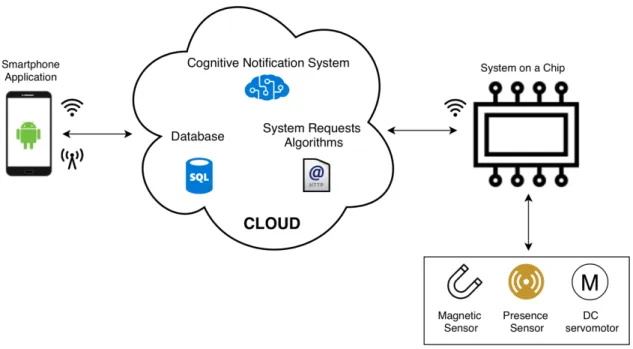
The developed system will be divided into three main modules as shown in figure 3.1: • Cloud platform
The cloud platform is the operations center of the system. It’s job is to answer and manage the user’s smartphone requests, to interact with the smart lock hardware and to study the activity generated data in order to deliver the main goal of this work, the cognitive smartphone application notifications.
• Smartphone application
The smartphone application communicates with the cloud platform through the web by sending and receiving requests from the cloud. Either is a request for the user to log in or to unlock the door, every user interaction with the system is made through the smartphone application requests.
• Smart lock hardware
Through a microcontroller, a magnetic sensor, a small DC servomotor, and a pres-ence sensor the hardware will represent the smart lock itself. The microcontroller provides web connection, through Wi-Fi technology, that enables the connection of all the hardware with the cloud platform. This allows the three modules to be connected between them through the web, making the cloud platform the center of all system’s operations.
In order to understand all the system features and to develop the system itself, it’s important to start with the system modeling.
C H A P T E R 3 . S Y S T E M M O D E L I N G
Figure 3.1: System prototype diagram
Section 3.1 is focused onto individually explaining the role of all the major modules of the system and to properly understand the importance of each one in the whole system.
Section 3.2 presents a system model that describes the whole system operation and behaviour.
Section 3.3 makes an approach to all the different system functions, in order to under-stand what is happening behind each system function.
Section 3.4 aims to describe the data model that is necessary to implement so that the system works flawlessly and, at the same time, ensuring that every function requests are met.
3.1
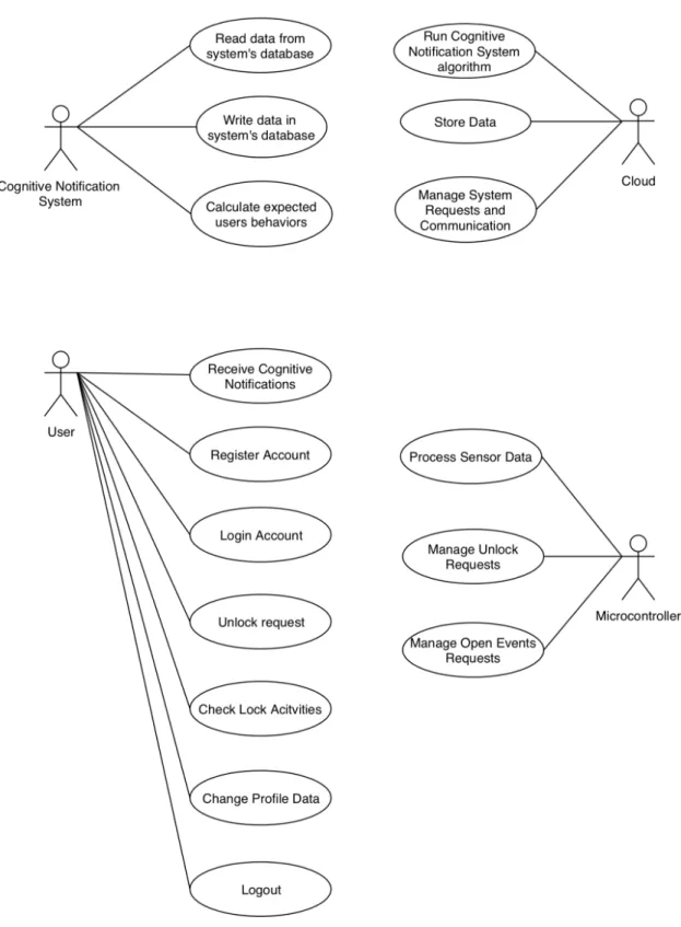
Use cases
This section aims to describe the different functionalities, roles and use cases that define each one of the system’s main modules. Figure 3.2 represents the system use case diagram, where each one of the system’s main modules is represented by an Actor that is linked to the use cases that each Actor performs. This diagram is focused on each module main use cases. A deeper approach to each one is made in the respective module’s section.
3 . 1 . U S E C A S E S
C H A P T E R 3 . S Y S T E M M O D E L I N G
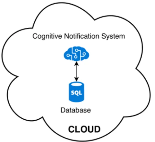
3.1.1 Cognitive notifications
Despite the fact that the notifications algorithm runs inside the dedicated server at the Amazon Web Services (AWS) cloud platform, it’s the most important part of all the work, making it fair for them to be considered a main system module.
The smartphone application cognitive notifications goal is to help the system admin-istrator to monitor the smart lock usage and its users. This could be an important feature either for a company to control its employee’s arrivals at the office, for parents who want to be warned when something unusual happens with their kids or even if the system administrator wants to be warned when the maid has not arrived in time at his house.
They are called cognitive notifications because they are based on previously acquired knowledge that is stored in the system’s database. Since every user has its own habits and routines, every time they use the smartphone application to access the building through the smart lock an activity log is generated for that specific user that helps to generate the cognitive notifications. Despite both the system administrator and regular users can use the smart lock, they play two different roles on the notification system:
• System administrator: can use the all the smartphone application and smart lock functions and it’s the only one who receives the notifications that are generated by the smart lock usage;
• Regular user: uses the smart lock just like the system administrator but is unable to receive notifications that may warn about other users behaviours and routines. Each user activity helps to build the knowledge needed to generate the notifications. A notification is sent to the system administrator when a user has a different behaviour than the previous ones that he had, so if a specific user unlocks the smart lock always around the same time, but there’s one day that he doesn’t, a notification is fired to the system administrator letting him know that that specific user is late.
Figure 3.3: System’s cloud with focus in the Cognitive Notification System and database interactions
3 . 1 . U S E C A S E S
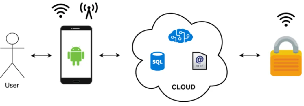
3.1.2 Cloud
The cloud role in this work is to be the center of operations of all the system, as shown in figure 3.4. It has the capability of managing all the smartphone application and smart lock hardware HTTP requests, store all the activity generated and users data and, at the same time, it runs the algorithm that triggers the application cognitive notifications.
Figure 3.4: Cloud communications diagram
3.1.3 Hardware
The physical smart lock prototype is composed by:
• Microcontroller with wireless communications module; • Door lock actuator;
• Door position sensor; • Presence sensor;
• Light Emitting Diode (LED).
The microcontroller is programmed to connect, through Wi-Fi technology, to the web in order to receive users unlock requests, to perform lock and unlock actions through the door lock actuator and, at the same time, read the door position sensor to understand if the door is opened or closed and the presence sensor so that the system knows if there is anyone at the door where the smart lock is assembled, this helps the cloud to register the user’s activity and adds a security layer by preventing unlock actions when there no one at the door. The smart lock hardware prototype connects directly to the cloud through HTTP requests as figure 3.5 shows and operates as shown in figure 3.20.
C H A P T E R 3 . S Y S T E M M O D E L I N G
Figure 3.5: Smart lock hardware communications diagram
3.1.4 User/Smartphone Application
Through the smartphone application, the user can perform several actions. After signing up and while logged in, the user should be able to control the door lock mechanism in order for it to perform an unlock action. It’s also possible to check an activity log where the ten last smart lock activities are listed and to change personal data such as the username, first name, last name and the password. Summing up, the smartphone application has the following features:
• User register/login/logout; • User profile edit;
• Smart lock unlock action control; • Smart lock activity log.
This smartphone application has been developed for Android-based smartphones and its operations are based in Hyper Text Transfer Protocol (HTTP) requests that are made to the cloud through the web as shown in figure 3.6.
Figure 3.6: Smartphone application communication with the cloud diagram
3 . 2 . S Y S T E M M O D E L
3.2
System model
Section 3.1 is focused on describing the functionalities of the work’s individual modules to gain a greater perception of each one’s role in the whole system.
This section aims to describe the whole system behaviour in a more detailed way, in order to properly modulate and implement each one of this work’s modules and to pursue an easy integration between them. Describing the system’s behaviour is also important to understand the interactions between all the modules, and the flow of actions that define the correct system implementation.
As explained in section 3.1 the user controls the smart lock hardware through the smartphone application with the cloud acting like the middleman that coordinates all the system requests between all the modules. That means that everything that happens in the whole system, represented in figure 3.7, is controlled, checked, registered or even authorized by the cloud.
Figure 3.7: Cognitive Notification System
To better describe the different scenarios where the modules that take part in the system interact, five sequence diagrams were used. Sequence diagrams are one of several different Unified Modeling Language diagrams and, are used with the purpose to describe and show the interactions between objects in a sequential order that those interactions occur, [32]. Sequence diagrams are designed to provide a general flow of what can happen in a system during a regular system usage, without focusing on the details and specifics of what’s happening in each module. The diagrams in figures 3.8, 3.9, 3.10, 3.11 and 3.12, were designed with the fact that all the systems are up and running in mind.
C H A P T E R 3 . S Y S T E M M O D E L I N G
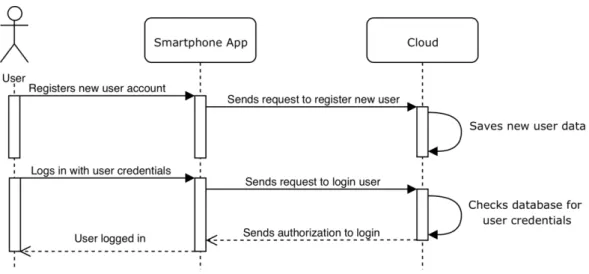
Figure 3.8: Register and login sequence diagram
The following diagrams assume that the user is already registered and only needs to login in order to perform different actions.
Figure 3.9: Check profile data sequence diagram
3 . 2 . S Y S T E M M O D E L
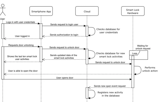
Figure 3.10: Unlock action sequence diagram
C H A P T E R 3 . S Y S T E M M O D E L I N G
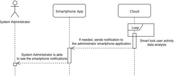
The sequence diagram shown in 3.12 was designed considering the fact the the system administrator doesn’t need to be logged in to receive the cognitive notifications in his smartphone.
Figure 3.12: Cognitive notification system sequence diagram
The next section approaches the detailed operations of each system module and func-tionalities.
3.3
System functions
Now that the whole system model is described in section 3.2, with the help of the sequence diagrams in figures 3.8, 3.9, 3.10, 3.11 and 3.12, it’s important to define and describe the specific behaviour for the system’s different functionalities briefly mentioned in 3.1.
3.3.1 Cognitive notifications function
The cognitive notifications function runs entirely in the cloud platform. It analyses the data generated through the user’s interaction with the smartphone application and consequently with the smart lock hardware and creates enough knowledge to understand each user routines and fire the notifications to the system administrator smartphone application. It all begins with the user performing several unlock actions through the smartphone application in order to unlock the door and enter the building where the smart lock prototype is assembled. By gathering the smart lock usage data in the cloud platform database, the notification algorithm is able to predict when a given user is going to unlock the door and by having a next unlock action predicted time the system will wait for that given user to unlock the door within a time window. If it happens, the new activity is added to the database and used to recalculate the new predicted unlock activity, if not, the notification, warning the system administrator that the user is late, is fired to the system administrator. The notification is only sent after a trigger time, thirty minutes, that is defined in the cloud cognitive notification algorithm. That trigger
3 . 3 . S Y S T E M F U N C T I O N S
time defines a gap between the user predicted time of arrival and the notification being sent to the system administrator. This specific mechanism prevents the arrival of a great number of unnecessary notifications to the system administrator smartphone. Another important feature that allows the system to perform in a better way, is the fact that each day is divided in three periods. This prevents that an unexpected unlock and entry action distorts the smart lock usage and eventually mess up the notifications send timings. The cognitive notification function is described in figure 3.13 and was designed assuming that the system’s database has enough user activity data to process.
Cognitive notification trigger time arrived?
Figure 3.13: Cognitive notifications function flowchart
3.3.2 Register function
The smart lock user-to-be has to register himself in the system in order to use it. The register action is performed, by the user-to-be, through the smartphone application by inserting his own personal data and pressing the button that proceeds with the action that creates a new user account. After this action, the inserted data is verified in the cloud and if everything is right the new user is now free to login in his personal smartphone
C H A P T E R 3 . S Y S T E M M O D E L I N G
application account and able to freely use the smart lock application functions. The register function is described in detail in the following figure 3.14 and was designed assuming that the user-to-be is already in the smartphone application register screen.
Figure 3.14: Register function flowchart
3.3.3 Login function
After registering himself, the user is able to log in and access all the smartphone ap-plication functionalities. In order to login into the app, the user has to fill the correct credentials for the application to know who is logging in and press the login button. After pressing the login button the cloud receives the login request and verifies if the creden-tials are correct. If the answer is positive, a new user session is created. If the user inserts credentials that don’t match the credentials of a registered user, it receives a login error message. The login function is described in the following figure 3.15 and was designed assuming that the user that is about to log in is already in the smartphone application login screen.
3 . 3 . S Y S T E M F U N C T I O N S
C H A P T E R 3 . S Y S T E M M O D E L I N G
3.3.4 Logout function
Logout function is the simplest one of this work. The logged in user has the possibility to log out from the smartphone application from several differente screens. This action can prevent unknown people to access our smart lock smartphone application and con-sequently to gain control over the smart lock itself. The logged in user that wants to log out from the smart lock smartphone application has to press the logout button. After that, the smartphone application leads the user to the login screen preventing anyone to control the system through the application. This flow is shown in figure 3.16 and was designed assuming that user is already logged in.
Figure 3.16: Logout function flowchart
3.3.5 Edit user profile data function
Smart lock users have also the possibility to change their own personal data through the user info screen as focused in 3.1.4. For the user to accomplish a successful change of their personal data in the system, they must go to user profile screen and change the field, or fields, that demand a change and press the save changes button. This action will trigger an update user data request into the cloud, that will save the new user profile data in the database. This process is described in figure 3.17 assuming that the user that wants to change his own personal data is already logged in and in the user profile screen.
3 . 3 . S Y S T E M F U N C T I O N S
Figure 3.17: Edit user profile data function flowchart
3.3.6 Activity log function
The system smartphone application gives the users the possibility to check their own smart lock system activity log. This function aims to show the user the last ten smart lock unlock actions that were performed by himself. It features the user’s username and a timestamp (date and time) that shows when it was performed. As mentioned, the users can only see their own activity, although the system administrator can check not only his own activities but also the other users activities, this is limited to the ten last unlock actions. The process that leads to displaying the data in the smartphone application is described in figure 3.18 that was designed assuming that the user is already logged in.
C H A P T E R 3 . S Y S T E M M O D E L I N G
Figure 3.18: Activity log function flowchart
3.3.7 Unlock function
Unlock is one of the system’s core functions. This functionality makes it possible to gather the smart lock activity data that is used to generate the cognitive notifications that are fired to the system administrator. To use this specific feature, the user must be at the smart lock screen in the smartphone application and press the unlock button in order to send a request to the cloud that will give the hardware authorization to unlock. After this initial process, the magnetic sensor will read the door state aiming to understand if the user opened the door, or not, during the next thirty seconds. If the user opens the door, the hardware sends a request to the cloud to save a new log into the smart lock activity database, if not, the smart lock locks the door automatically. The detailed process of unlocking the smart lock is described in figure 3.19 and was designed assuming that the user is logged in and is already in the smart lock screen in system’s smartphone application
3 . 3 . S Y S T E M F U N C T I O N S
C H A P T E R 3 . S Y S T E M M O D E L I N G
3.3.8 Smart lock hardware
The hardware module plays a major role in the whole system, despite the fact of not being a function on its own, it uses different functions to succeed in the tasks that are assigned to it. The hardware represents the smart lock itself, it helps the system to have a physical representation of the unlock action itself and is extremely important assuring that the generated data is quite reliable. As mentioned in 3.1.3, the hardware is composed by the a microcontroller with wireless communications, a door lock actuator, a door position sensor and a presence sensor. To work properly, the hardware starts to execute a calibration routine to assure that the door lock is in the lock position and connects itself to the predefined Wi-Fi network. After this, it stands still until an unlock request from the cloud arrives. After the request arrives the presence sensor turns on so the system if there is anyone around, if yes the door unlocks and the green LED turns on to let the user know that the door is now unlocked. After, the door position sensor waits for the door to open in order to send the cloud the permission to register a new user activity in the database. If the door is opened the activity is registered. If not, the door locks automatically after thirty seconds. The door position sensor also helps in avoiding unnecessary lock/unlock actions. The detailed operations of the hardware module are described in figure 3.20.
3 . 3 . S Y S T E M F U N C T I O N S
C H A P T E R 3 . S Y S T E M M O D E L I N G
3.4
Data model
To support the, previously approached, system functions and operations, this work needs to have a solid and strong system data model. This data model is able to store different categories of data that have different purposes and roles throughout all the system’s operations. In this section are itemized and described the different data sets that are needed for the system to work as previously described in sections 3.2 and 3.3.
• User - User data table stores the personal data of all the system users. Each user is identified through an unrepeatable Identifier (ID) and the personal data is also composed by the user’s first name, last name, username and password.
• Role - Role table stores the two different system roles, regular user or system ad-ministrator. This table is connected directly to the User table in order to identify each user’s role.
• Lock - Lock database table ensures that all the requests that travel through the system are connected to the correct smart lock. This is guaranteed by generating a unique ID, that identifies the physical hardware, of each one of the smart locks that may exist in the network. This avoids users to communicate with other smart locks, that they shouldn’t have access to since the requests are directed only to a specific one. Despite the fact that the developed system has only one lock, it’s important to have this table in order for the system to grow in future developments. This table is composed by a lock ID that identifies the smart lock hardware and a variable that stores the name of the lock itself. It connects to the Unlock Request and Open History tables.
• Unlock Request - This table receives an entry every time an unlock request is made and since the unlock request is valid for only thirty seconds it’s mainly used to check if the unlock request has expired or not. The table is composed by a request ID, a datetime variable that stores the date and time in which the request was made, and connects to the User and Lock tables in order to link request with a specific user and lock.
• Open History - The Open History table has the main task to save all the user’s activity history. To do that, this table stores the date and time of each user’s unlock and entry action and assigns each one of them to one of the three available day periods. This helps the cognitive notification system to segment the notifications. At the same time, it connects to the User and Lock table to assign a specific user and lock to that unlock action.
• Entry History - This table is very similar to Open History table, the main difference is that Entry History table only allows each user to have registered an unlock and entry action per period per day, so that the system administrator smartphone doesn’t
3 . 4 . DATA M O D E L
get flooded with unnecessary notifications. This table stores the day of the year (from 0 to 365) and the period of the day in which the unlock and entry action was registered. It also connects to the User table in order to link the registered action to a specific user.
• User Late - The cognitive notifications algorithm studies the data in the Entry History table every minute, if the user is late, an entry in the User Late table is created. The creation of a new entry in this table trigger the notification send to the system administrator smartphone. This table connects to the User table where it obtains access to the user ID. Since that table is also connected to the Entry History table, it is possible to access to the day of the year value and to the period of the day in order to maintain full register of the sent notifications.
![Figure 2.1: Example of a message sent through Bluetooth from Nuki smartphone applica- applica-tion to Nuki Smart lock, taken from [8].](https://thumb-eu.123doks.com/thumbv2/123dok_br/19200172.953450/26.892.258.677.617.787/figure-example-message-bluetooth-smartphone-applica-applica-smart.webp)
![Figure 2.2: Example of a message sent through the internet from Nuki smartphone appli- appli-cation to Nuki Smart lock, taken from [8].](https://thumb-eu.123doks.com/thumbv2/123dok_br/19200172.953450/27.892.217.637.148.300/figure-example-message-internet-nuki-smartphone-cation-smart.webp)
![Table 2.1: Comparison of di ff erent wireless technologies, adapted from [13]](https://thumb-eu.123doks.com/thumbv2/123dok_br/19200172.953450/32.892.147.788.186.475/table-comparison-di-ff-erent-wireless-technologies-adapted.webp)