FORMALIZING MARKUP LANGUAGES FOR USER INTERFACE
Dissertac¸˜ao para Mestrado em Inform ´atica
Escola de Engenharia UNIVERSIDADE DO MINHO
FORMALIZING MARKUP LANGUAGES FOR USER INTERFACE
Dissertac¸˜ao submetida `a Universidade do Minho para obtenc¸ ˜ao do grau de Mestre em Inform ´atica, ´area de especializac¸ ˜ao em Sistemas Distribu´ıdos, Comunicac¸˜oes por Computador e Arquitectura de Computadores, elabo-rada sob a orientac¸ ˜ao do Professor Doutor Jos´e Nuno de Oliveira, Pro-fessor Associado do Departamento de Inform ´atica da Universidade do Minho.
Dissertac¸˜ao desenvolvida no ˆambito do Projecto EUREKA IKF (E!2235)
Escola de Engenharia UNIVERSIDADE DO MINHO
This document presents a Dissertation theme, as integral part of Masters Degree in
Distributed Systems, Computers Architecture and Computers Communication.
The work has as primary objective the application of formal methods in the specifi-cation of presentation layer. Even reaching several relevance HCI concerns, the scope focus essentially on the way how formal methods can be explored to specify user in-terfaces described using markup languages.
The state-of-the-art analysis of user interface markup languages and UIML - User Interface Markup Language formal specification are main contributions. Therefore the
tabular graphical object OLAP main features are formally specified in VDM-SL and
animated using UIML.
This research should be considered as a contribution towards a definition of a visual component library , with user interfaces components composition and reuse.
I would like to thank my supervisor Professor Jos´e Nuno Oliveira, member of DI
(Department of Informatics, Minho University1), who encouraged all formal methods
research and initiatives at the University, for his useful support and advice during this work. I am also grateful to Mark Adams and James Helms Harmonia members, for their enthusiastic support along this research as well for the availability of their UIML supporting tools.
To all which improved the English in this thesis, I am also very grateful. Thanks also to all my friends which have made contributions to this work.
would like to thank my Ana for her admirable patience and support during this work, and our daughters Aninhas e Ritinha, which were deprived of their father for the best part of these years.
1
http://www.di.uminho.pt
Abstract ii Acknowledgements ii List of Figures ix List of Tables x Listings xi 1 Introduction 1 1.1 Overview . . . 1 1.2 Problem Statement . . . 2
1.3 Motivation and Objectives . . . 5
1.4 Summary of Contributions . . . 10
1.5 Structure of the Dissertation . . . 10
1.6 Document support . . . 11
2 Research Foundations 13 2.1 The context . . . 13
2.2 User Interface Properties . . . 14
2.3 User Interface Models . . . 16
2.3.1 “Ancient” HCI models . . . 16
2.3.2 XForms Model . . . 18
2.3.3 The N-Tier Model . . . 19
2.3.4 MIM Model . . . 20
2.3.5 Other research in HCI modelling . . . 21
2.4 User Interfaces Analysis and Specification . . . 22
2.4.1 Adaptable Interfaces . . . 23
2.4.2 Formal Methods and Specification . . . 25
2.4.3 VDM-SL . . . 29
2.5 User Interface Design . . . 32
2.5.1 UMLi . . . 34
2.6 User Interface Programming . . . 36
2.6.1 UI Programming Methods . . . 36
2.6.2 N-Layer architecture . . . 39
2.6.3 Tools and Applications . . . 41
2.7 Data description and manipulation . . . 44
2.7.1 Multidimensional Analysis . . . 44
2.7.2 OLAP . . . 50
2.8 User Interfaces Evaluation . . . 51
2.9 Conclusions . . . 51
3 Markup Languages for User Interface description 53 3.1 Presentation . . . 53 3.2 XIML . . . 54 3.2.1 Scope . . . 54 3.2.2 Requirements . . . 54 3.2.3 Structure . . . 54 3.2.4 Importance . . . 55 3.2.5 Remarks . . . 56 3.3 XUL . . . 56 3.3.1 Scope . . . 56 3.3.2 Requirements . . . 57 3.3.3 Structure . . . 58 3.3.4 Importance . . . 59 3.3.5 Remarks . . . 60 3.4 UIML . . . 60 3.4.1 Scope . . . 60 3.4.2 Requirements . . . 61 3.4.3 Structure . . . 61 3.4.4 Importance . . . 63 3.4.5 Remarks . . . 65
3.5 Relationship between UIML and other UI Markup languages . . . . . 65
4 UIML Formal Specification 69 4.1 VDM-SL Specification . . . 69
4.1.1 Terminologies . . . 69
4.1.2 Presentation . . . 71
4.2 UIML Overview . . . . 71
4.2.1 The Structure of an UIML Document . . . . 71
4.2.2 UIML document . . . . 72
4.2.3 UIML Namespaces . . . . 75
4.2.4 UIML Elements . . . . 76
4.3 UIML Formalization . . . 76
4.3.1 Considerations . . . 76
4.3.2 VDM-SL Types and common UIML attributes . . . . 78
4.3.3 UIML top elements . . . . 79
4.3.4 Interface description . . . 81
4.3.5 Peer Components . . . 106
4.3.6 Templates - Reusable Interface Components . . . 115
4.4 Invariants . . . 117
4.4.1 Overview . . . 117
4.4.3 The uniqueness of ID’s . . . 118
4.4.4 Attribute part-name must refer an existing part ID attribute . . 142
4.4.5 Auxiliary Functions . . . 147
4.5 Remarks . . . 149
5 Case study: Table IO 150 5.1 Overview . . . 150
5.2 Fundamentals of Table IO Formalization . . . 150
5.2.1 Considerations . . . 150
5.2.2 Table model . . . 152
5.3 Table VDM-SL specification . . . 157
5.3.1 General table methods . . . 160
5.3.2 Towards Multidimensional Analysis . . . 173
5.3.3 Auxiliary functions . . . 188
5.3.4 Pretty print functions . . . 196
5.3.5 AST Conversion . . . 201
5.3.6 UIML visualization . . . 206
5.4 Summary . . . 209
6 Prototype and Supporting Tools 210 6.1 Prototype . . . 210
6.2 Supporting tools . . . 211
6.2.1 Phase 1 - Transcoding UIML to VDM-SL . . . 211
6.2.2 Pretty Print . . . 213
6.2.3 Phase 2 - Verifier . . . 213
6.2.4 Phase 3 - Abstraction . . . 214
6.2.5 Phase 4 - Rendering UIML . . . 214
7 Conclusions and Future Work 216 7.1 Overview . . . 216
7.2 Discussion and Future Research . . . 218
7.2.1 UIML formal specification refactoring . . . 219
7.2.2 Tool support for language refactoring . . . 227
7.2.3 IO Visualization . . . 228 7.3 Final Remarks . . . 231 Bibliography 232 Appendices 242 A VDM-SL Notation 243 B W3C XML 248 C UIML DTD 257
E Supporting Tools 266
E.1 Transcoding UIML7→ VDM -SL - uiml2vdm stylesheet . . . 266
E.2 Verifier VDM 7→ UIML - vdm2uiml . . . 279
E.2.1 Auxiliar Data Types . . . 279
F Prototype 285
G UIML Code examples 288
G.1 Stack UIML Code . . . 288
G.2 Table UIML Code . . . 291
H Stack VDM-SL Specification 293
Function/Method Cross-Reference Index 296
1.1 VBasic visual Components . . . 6
1.2 Delphi visual Components . . . 6
1.3 Java AWT/Swing visual Components . . . 7
1.4 Interfaces development . . . 8
1.5 Example of multidimensional representation . . . 9
1.6 Phases of the formalization process . . . 10
1.7 Stack implemented in Visual Basic . . . 12
1.8 UIML stack rendered to Java . . . 12
2.1 The basic software architecture and the corresponding layered model for Human-Computer Interaction (adapted from [JBK89]) . . . 15
2.2 Seeheim Model . . . 16
2.3 Arch Model. . . 17
2.4 MVC -Model View Controller. . . 18
2.5 PAC-Presentation-Abstraction-Control. . . 18
2.6 XForms architecture (adapted from [Rec03f]) . . . 19
2.7 N-Tier Model . . . 20
2.8 Meta-Interface Model (adapted from [Pha00]) . . . 21
2.9 XXL/XiBuilder Visual Builder Graph View . . . 24
2.10 Explanation of symbols in the definition of adaptation (adapted from [SC03]) 25 2.11 User Interface Reverse Engineering . . . 28
2.12 User Interface Forward Engineering . . . 28
2.13 VDM-SL module structure. . . 31
2.14 ConnectUI - UMLi example of User Interface Diagram (generated using AR-GOi version 0.8.0) . . . 35
2.15 Components of user interface software (adapted from [Mye96]) . . . 36
2.16 Generations of Architectures . . . 40
2.17 N-Tier Architecture . . . 41
2.18 HyperCube . . . 45
2.19 Relation versus Multidimensional Model . . . 46
2.20 Multidimensional Rotation . . . 48
2.21 Ranging operation . . . 48
2.22 Schema and instance for the Sales Region dimension . . . 49
2.23 Rolling-Up and Drilling-down. . . 49
3.1 Basic structure of XIML language (adapted from [PE02b]) . . . 55
3.2 XUL window example . . . 60
3.3 The uiml element . . . 63
3.4 The peers element . . . 64
3.5 The interface element . . . 64
3.6 Portability of UIML (adapted from [PA99]) . . . 66
4.1 Stack Java/UIML interface . . . 74
4.2 <uiml> hierarchy . . . 76
4.3 <interface> hierarchy . . . 78
4.4 <peers> hierarchy . . . 79
5.1 Sales volumes HyperCube. . . 151
5.2 Sales: Month * Low × High . . . 153
5.3 Sales: Month * High . . . 153
5.4 Sales: Month × Color * High . . . 154
5.5 Sales: North ⊕ South * Total . . . 154
5.6 Sales table information . . . 160
5.7 delRow operation result . . . 163
5.8 Single column project operation . . . 166
5.9 Multiple column project operation . . . 167
5.10 New column applying addCol . . . 169
5.11 Result of rotation . . . 175
5.12 Result of applying mda . . . 177
5.13 Sales per region. . . 180
5.14 rollUp process . . . 181
5.15 UIML Visualization process . . . 206
5.16 Result of applying outHtml operator . . . 207
5.17 Result of applying u2h render to table.uiml . . . 209
6.1 Prototype architecture . . . 210
6.2 VDM/UIML integration prototype. . . 211
6.3 Harmonia LiquidUI UIML browser . . . 215
7.1 Example of<uiml> hierarchy elements . . . 226
7.2 Abstract and Concrete graphical visualization of basic elements . . . 229
7.3 A∗seen as an array . . . 229 7.4 (Exp ,→ C ) representation . . . 230 7.5 (A × B ) ,→ C . . . 230 7.6 (A ,→ Exp) representation . . . 231 7.7 A,→ D × (B ,→ C ) representation . . . 231 B.1 Essential XML rules . . . 250 B.2 XML working process . . . 252 D.1 UIML 3.0 Reference . . . 265
F.1 VDM/UIML integration test case . . . 285
F.3 Prototype: Rotation operation . . . 286 F.4 Prototype: Consolidation operation . . . 286 F.5 Prototype: Hiding column operation . . . 287
1.1 Non normalized Relational Structure . . . 8
2.1 VDMl-SL constructors . . . 31
2.2 A two dimensional table. . . 47
2.3 Relational SQL query result . . . 47
4.1 UIML elements . . . 77
5.1 Example of table data display . . . 152
7.1 Abbreviations for UIML element names . . . 220
1.1 Function F(x ) = x2implemented in BASIC . . . 3
1.2 A PASCAL STACK implementation . . . . 3
3.1 XUL User Interface example . . . 59
3.2 UIML Hello World example (adapted from [AH02]) . . . 61
3.3 WML<peers> example . . . 62
3.4 WML rendering result . . . 62
3.5 Typical UIML document . . . 63
4.1 UIML “Hello World” example . . . . 73
4.2 UIML “Hello World” example - WML<peers> description . . . 73
4.3 UIML “Hello World” example - WML output” . . . . 73
4.4 UIML Stack Interfaces specification . . . . 74
4.5 Skeleton of a UIML document . . . . 75
5.1 VDM-SL Sales table . . . 206
5.2 UIML table code generated by outUiml . . . 207
6.1 XSL template to “transcode”<uiml> element . . . 212
6.2 Excerpt of UIML Hello example . . . 212
6.3 Extract of vdm2uiml VDM-SL script . . . 213
6.4 UIML generated from vdm2uiml VDM “script” . . . 213
7.1 UIML code to describe a Java AWT label . . . 225
B.1 XML document . . . 248
B.2 A sample DTD . . . 250
B.3 A sample schema written in W3C XML Schema syntax . . . 250
B.4 Another XML example . . . 254
B.5 XSL example . . . 254
B.6 HTML generated from XSL . . . 255
C.1 UIML DTD 3.0 . . . 257
E.1 XML Stylesheet to generate VDM-SL from UIML . . . 266
G.1 Complete UIML Stack user interface specification . . . 288
G.2 UIML “template” for table definition . . . 291
Introduction
1.1
Overview
There will always be old software(Hausi Muller )
The human brain is able to learn and to reason in vague and imprecise contexts. It can decide upon imprecise and qualitative data. In contrast, formal methods (logical and mathematical) demand accurate and quantitative data.
Since the computer machine appeared, we understood its capabilities, when it was properly used. It is true that the computers have important capabilities, but they still are far away from being a match for the human intelligence. Nevertheless man is making an effort in “instructing” these machines in that sense.
It is one of the great challenges of ours days, that complex data, contained in databases of great dimension and longevity are processed and which are increasing exponentially in size. The Internet provides obvious evidence of all this.
From another perspective, for the actual companies it is crucial the full integration and consistency of all the information which flows or is stored in its databases. The number of specific and different applications, manipulating this information, is nec-essarily big. Maintenance and support of these applications requires expensive team work.
The (conventional) Relational Database Management Systems (RDBMS) no longer can guarantee timely efficiency in the answers to complex queries. The treatment of information in bidimensional format (tables and spreadsheets, for example), the inability of the analysis, transformation and consolidation of such information, restrict the overall application of these systems.
If we look at the young history of Computer Science (almost nothing existed be-fore 30 years), we find orientations more or less objective, always focusing on the principle of trying to reach something that does not exist. A lot of times following typ-ical “azimuthes” with “boomerang” effect, believing that, tuning certain options and returning again to the starting point, will reach something different, innovative or not. Practically similar to the new fashion effect. Something like “d´ej`a vu”.
This can be easily seen in several programming language paradigms, which appear
everyday. If we carry these thoughts to the User Interface development area in several computer applications, we obtain a not less important question and perhaps, more critical, since progress on it was a little shallow along the last years.
From observing multiple facts, one can observe that large companies involved in software development, invest hardly in user interface quality and associated features.
HCI -Human-Computer Interaction [SIG, oM03], is a branch of research in Com-puter Science, focused precisely on this kind of problems, where one tries to get near
to human behavior, in the way the application functionality is presented to the user. Ergonomic issues, as well as organization and process logic are key points in these works.
The scope of this research work, although it can reach, with some relevance, HCI concerns, focus essentially on the way how formal methods can be explored to specify the user interface graphical objects and associated features.
We focus on an initial and specific interface and its related issues which can then be translated to different platforms. The Web is an evidence of this. Several entities are converting their normal applications to be available also in the Internet. The quick
Web spread, the B2B1scenario, the emergence of EAI2concerns, can justify many of
these decisions.
The advantages of formal specifications of complex systems using formal meth-ods are well known. It is known and accepted by a considerable group of persons, as a way to avoid ambiguities and clearly guarantee correctness and consistency of the developed programs. In this context, it is useful to experiment these methods on user interface development, trying some kind of merging process of new methods specifi-cations with existing graphical objects specifispecifi-cations.
ProgramSpecification = Specification(Data + Services + Interfaces) As a consequence of this large set of graphical elements, many of them only found in pure commercial application, its formal specification process, towards a Visual
Com-ponent Library - VCL, could becomes complex. This complexity can even increase
during the tentative abstraction of real problems.
An interface specification, based on the intended model, i.e., strongly supported by a top-down analysis of existent interface and end user opinions, can conduce to a partial system specification. This is due to the analyzed interfaces inability to represent correctly the all system. In this sense, to get a deep abstraction, we think it is funda-mental to consider also the interfaces specification based on operations, properties and services.
1.2
Problem Statement
During all this period of continuous advances in the development of software tech-nologies, the programmer always needed to deal with two complementary challenges:
1
B2B - Business to Business
2
from one side he needed to solve problems and from the other side he needed to do it properly (that is, with correction and adequate performance).
Jumping from the interpreted to the compiled programming language paradigm cannot be justified only by quality. We can not say “one language is better than an other” without discussing whether it explores efficiently the capacities of the support technologies, namely the Hardware.
Let us in retrospective, review some programming languages/technologies, look-ing for very simple examples of common problems.
Listing 1.1, presents a piece of BASIC source code which implements the
mathe-matical function F(x ) = x2, applied to a range of values from A to B.
Listing 1.1: Function F(x ) = x2implemented in BASIC
2 REM TABULATE A FUNCTION F (X) FROM X=A TO X=B IN STEPS DX
3 REM ENTER THE FUNCTION F (X) IN THE NEXT LINE
5 DEF FN F (X) =Xˆ 2 6 : 7 INPUT ”FROM X= ” ; A 8 INPUT ” TO X= ” ; B 9 INPUT ” IN STEPS OF ” ;DX 10 :
11 FOR X=A TO B STEP DX
12 Y=FN F (X)
13 PRINT X , Y
14 NEXT X
15 :
16 END
We observe that the whole program (in this case interpreted), constitutes only one source code document. The way the information reaches the end user (at this time, the term User Interface was not common) does not deserve any special attention.
The next program fragment (Listing 1.2), implements a Stack structure in Pascal, a compiled language. Although some of the source code organization is in modules,
functions or procedures, some concepts, related with data calculation, user integration
and interaction are merged when reading values and presenting results (see e.g. the
addToStack function)
Listing 1.2: A PASCAL STACK implementation 1 {∗STACK module - by l u f e r ∗} 3 program e x S t a c k 1 ( i n p u t , o u t p u t ) ; 4 t y p e 5 p c e l l = ˆ c e l l ; 6 c e l l = r e c o r d 7 no : i n t e g e r ; 8 d a t a : s t r i n g ; 9 n x t : p c e l l ; 10 end ; 12 var 13 t o p , temp : p c e l l ; 14 n s e r i a l , n c o u n t , ID : i n t e g e r ; 15 ch : c h a r ; 16 d a t a : s t r i n g ; 18 p r o c e d u r e a d d T o S t a c k ;
19 b e g i n 20 i f t o p = n i l t h e n 21 b e g i n 22 new ( t o p ) ; 23 t o p ˆ . n x t : = n i l ; 24 end 25 e l s e 26 b e g i n 27 temp : = t o p ; 28 new ( t o p ) ; 29 t o p ˆ . n x t : = temp ; 30 end ; 31 t o p ˆ . no : = n s e r i a l ; 32 n s e r i a l : = n s e r i a l + 1 ; 33 w r i t e l n ( ’ C e l l o f ID ’ , t o p ˆ . no : 4 , ’ was a d d e d a t 34 t h e t o p o f s t a c k ! ’ ) ; 35 w r i t e l n ( ’ P l e a s e I n p u t some d a t a ’ ) ; 36 r e a d l n ( t o p ˆ . d a t a ) ; 37 w r i t e l n ; 38 end ; 40 p r o c e d u r e r e m o v e F r o m s t a c k T o p ; 41 b e g i n 42 i f t o p <> n i l t h e n 43 b e g i n 44 temp : = t o p ; 45 t o p : = t o p ˆ . n x t ; 46 w r i t e l n ( ’- - - ’ ) ; 47 w r i t e l n ( ’ C e l l ID = ’ , temp ˆ . no ) ; 48 w r i t e l n ( ’ D a t a : ’ , temp ˆ . d a t a ) ; 49 w r i t e l n ( ’- - - ’ ) ; 50 w r i t e l n ;
51 w r i t e l n ( ’ C e l l o f ID ’ , temp ˆ . no : 4 , ’ was removed 52 f r o m t o p o f s t a c k ! ’ ) ; 53 w r i t e l n ; 54 d i s p o s e ( temp ) ; 55 end 56 e l s e 57 b e g i n 58 w r i t e l n ( ’ S t a c k i s empty ! ! ’ ) ; 59 w r i t e l n ; 60 end ; 61 end ; 63 p r o c e d u r e S c a n S t a c k ; 64 b e g i n 65 temp : = t o p ; 66 n c o u n t : = 1 ; 67 i f temp = n i l t h e n 68 b e g i n 69 w r i t e l n ( ’ S t a c k i s empty ’ ) ; 70 w r i t e l n ; 71 end 72 e l s e 73 w h i l e temp <> n i l do 74 b e g i n 75 w r i t e l n ( ’- - - ’ ) ; 76 w r i t e l n ( ’ T h i s i s ’ , n c o u n t : 4 , ’ t h C e l l ! ’ ) ; 77 w r i t e l n ( ’ C e l l ID = ’ , temp ˆ . no ) ; 78 w r i t e l n ( ’ D a t a : ’ , temp ˆ . d a t a ) ; 79 w r i t e l n ( ’- - - ’ ) ; 80 w r i t e l n ; 81 temp : = temp ˆ . n x t ; 82 n c o u n t : = n c o u n t + 1 ; 83 end ; 84 end ;
87 b e g i n 88 w r i t e l n ( ’ T h i s i s a Demo f o r u n d e r s t a n d i n g S t a c k ! ! ’ ) ; 89 n s e r i a l : = 1 ; 90 r e p e a t 91 w r i t e l n ; 92 w r i t e l n ( ’ P l e a s e S e l e c t f u n c t i o n ! ’ ) ; 93 w r i t e l n ( ’A) d d C e l l T o S t a c k R ) e m o v e C e l l F r o m S t a c k 94 S ) c a n S t a c k E ) nd ’ ) ; 95 r e a d l n ( ch ) ; 96 w r i t e l n ; 97 i f ( ch = ’A ’ ) or ( ch = ’ a ’ ) t h e n 98 AddToStack 99 e l s e i f ( ch = ’R ’ ) or ( ch = ’ r ’ ) t h e n 100 RemoveFromStackTop 101 e l s e i f ( ch = ’ S ’ ) or ( ch = ’ s ’ ) t h e n 102 S c a n S t a c k ; 103 u n t i l ( ch = ’E ’ ) or ( ch = ’ e ’ ) ; 104 w r i t e l n ( ’ P r o g r a m was a s s i g n e d t o end ! ! ’ ) ; 105 w r i t e l n ( ’ Bye ! ! ’ ) ; 106 end .
Thinking of (and more real critical) situations, like supporting bank information systems, insurance companies, etc., the scenario is the same. Surely much investment was made on improving and certifying these kind of systems. Not only large hardware equipment had to be acquired but also complex software had to be developed. Having done so, the whole attention was put on ensuring that“nothing wrong” could happen to the system. The way the operations were handled by the users, passed to a secondary plane. In summary, the interface remained the same for a long time even if the systems were frequently upgraded.
In ours days things are different. One can see the natural tendency of users to “accept” new technologies (while the number of end users is increasing), like Internet,
wireless, mobile devices, etc. Maybe because the systems are considered as being
stable and enough robust for their intended purposes.
Almost every company puts effort in having their business contents available in these new emerging resources. Many of the existing systems remain as they are and the interfaces need to be frequently transformed and many times created new ones to support the new devices. The main concern nowadays is to ensure interoperability among new software components, applications, etc., on top of existing ones.
However, user interface transformation or adaptation is not yet adequately handled and ensured. If not anarchic, it lacks scientific rigor. Chapter 2 addresses this topic.
An important question is: what is adaptability and how can it be, if it can be, mea-sured? We will see later (on section 2.4.1) that adaptation means changing a system to reflect changes in the environment. In the context of user interfaces, where end users can question non functional requirements such as usability, simplicity, etc., it will be interesting to analyze how visual component interfaces reflect them.
1.3
Motivation and Objectives
The work described in this thesis stands from the thoughts of Brad Myers [Bra98]. The area of the UI is an example of the strong influence of academic research in the
industrial way of doing things. It is often assumed mistakenly that, in case the univer-sities do not do it, industry will take charge of developing. There are several facts that reflect the erroneous way of this thinking.
Today practically all kinds of interface standards result from strong influences of the research in teaching institutions.
In its essence, this thesis work, intends to apply formal semantics techniques to the user interface development, in order to impose scientific rigor on the whole process, from interface specification and validation to its transformation (“transcoding”).
The application of formal methods should never surpass the limits of versatility, trying whenever possible to build the specification through the composition of compo-nents previously specified.
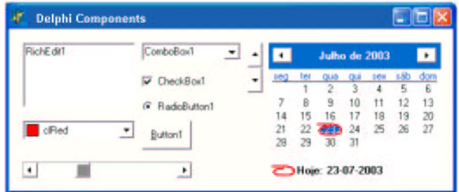
This work is targeted at formally specifying visual components, classifying new components and reusing existing ones that are already classified. We refer to visual components used in actual tools for Graphical User Interface development (GUI), such as ListBox, Button, TextBox, Menu (Figures 1.1,1.2 and 1.3), which lack rigorous specification, both at the functional (semantic) and structural (syntactic) levels.
Figure 1.1: VBasic visual Components
Figure 1.2: Delphi visual Components
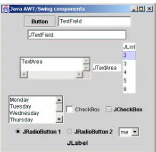
By applying formal methods, UI development becomes a rigorous discipline with focus on higher abstraction levels (relative to implementation), using visual
compo-Figure 1.3: Java AWT/Swing visual Components
nents and a semantic set of rules which describes the process.
The notation chosen to define components is supported on Sets Theory [Oli03]. The semantic specification of each component will resort to semantic models, describ-ing the distinct internal states, associated to execution of each operator. For instance, in a ListBox one must specify the effect of Insert, Remove or Select events of some of its items (in this case because a ListBox is a composite component).
The traditional process of application development, culminates with the creation of complex interfaces, which facilitate the interaction with the information system.
With the advent of Application Program Interfaces (APIs) and using some avail-able interface operators, one can create quickly and globally accepted development methods. However, the process of interface design appears for the developer as some-thing conditioned by the information organization on the database or any other infor-mation support system.
The choice of a ComboBox or a ListBox for instance, is done, knowing that these components will represent some specific information. In this way, any necessary change to an interface, could be a delicate and perhaps not very flexible process.
For all this process of UI development, this thesis suggests the use of formal meth-ods. User interface design should be based on formal specification, before its final representation or implementation on a particular platform.
The process usually starts from a data model, properly (or not) normalized, which describes the intended information system. Using a formal specification language,
VDM-SL in this case [Hop01], developers will try to specify the data model, by
iden-tifying the necessary components of the interface for its information visualization. It is a typing process that guarantees coherence in the final placement of the com-ponents in the interface layout. Also for each component it can be of interest the def-inition of conditions (invariants) which, in the later phase of layout placement, justify
its relative position.
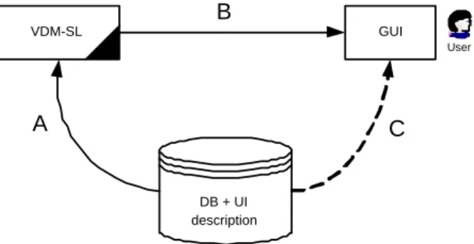
Figure 1.4 depicts the main intervenients int the user interface development pro-cess. C is the traditional method while A and B pictures the approach followed in this thesis. DB + UI description VDM-SL GUI User A B C
Figure 1.4: Interfaces development
In this figure, A represents the modelling process in our prototyping platform (VDM), of the intended data model. Database tables and their relationships will be represented in Set notation.
The B process carries out a simplification of the initial structures created by A, by a process of eventual matching of the available visual components for each structure specified. This process should finish with the respective interface presentation, in a specific environment.
By contrast, C represents the normal process of interface development. A specific software “translates” the data model in forms which will be the application interface.
Our approach will be described in Chapter 5, where all these concepts will be described in detail. Following we summarize this process, using a simple formal mod-elling process.
Consider the non (normalized) relational structure, depicted in Table 1.1. In this structure Student is the primary key and Mark is the final calculated mark considering
Lab and Exam marks.
Student Lab Exam Mark
Ant´onio 10 12 11
Ana 14 14 14
Table 1.1: Non normalized Relational Structure
Modelled in Sets notation, this structure is written as follows:
Student ,→ Lab × (Exam ,→ Mark ) (1.1)
From this expression, a normalized view can be derived by calculation:
We can now try to represent this structure using a multidimensional array (a tech-nology dealt with in Chapter 2), which constitutes one of the great advances of
Mul-tidimensional Analysis [Nig01]. The result can be represented in the next figure, as
follows: Ana Student Lab First Second 14 14 António 10 12 Exam Final 14 10 8 Student Lab António 10 Ana 14 12 Semester Mark First 8 Second 10 Final First 12 14 Exam Semester Mark First 8 Second 10 Final First 12 14 Exam
Figure 1.5: Example of multidimensional representation
The result of applying some operators associated to this kind of representation (later we will describe operators like Rotating, Ranging, etc.) could now be easily applied and observed.
In the context of using multiple development technologies, with reengineering and the process of integrating current and legacy systems an important demand and in the context of a continuous investment on distributed and mobile systems with end user interaction, it is essential the presence of a System Architect person.
The purpose of this work is to provide guidelines for user interfaces specification and development in computer science, based on formal methods as follows:
• to show the applicability of formal methods in the specification and development of interfaces;
• to show the applicability of formal methods in software reengineering processes; • to analyze the importance of the actual technologies of Markup languages in
integration processes;
• to create in VDM the kernel of a visual component library for user interfaces specification support;
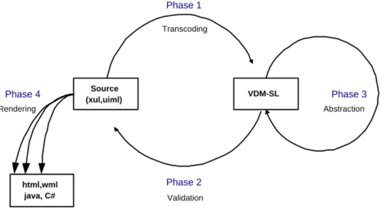
Figure 1.6 depicts the four main phases of our process:
• Phase 1 - Transcoding - developing of a mapping process from source code to
VDM-SL notation;
• Phase 2 - Validation - inverse process which will allows to obtain a source de-scription from a formal VDM-SL specification;
• Phase 3 - Abstraction - progressive abstraction of existent formal specification, using calculation.
VDM-SL Source (xul,uiml) html,wml java, C# Phase 1 Phase 2 Phase 3 Phase 4 Transcoding Abstraction Validation Rendering
Figure 1.6: Phases of the formalization process
• Phase 4 - Rendering - rendering mechanism to analyze the result in a particular platform.
Our work will focus onto the area of the specification through DSL - Domain
Spe-cific Languages [ABB+97] because, just as its name suggests, we will try to focus on components specification regardless or abstracting their implementing details, al-though continuing to support the creation of prototypes. We will use VDM-SL - The
Vienna Development Method Specification Language [IFA00c] as our specification
language. We will avoid following a specific programming language, working with
GPL - General-Purpose Languages.
1.4
Summary of Contributions
The main contributions of this dissertation are as follows:
• A formal specification of a particular Markup Language (UIML) • A XML StyleSheet to convert UIML to VDM-SL
• A VDM render to generate UIML from VDM-SL • A formal specification of a graphical Table
• A formal specification of some basic OLAP operators
1.5
Structure of the Dissertation
This dissertation puts forward a new strategy for user interface development. Quoting Vijay [Mac96], “user Interfaces are considered as one of the six core fields of
Com-puter Science and are regarded as the most critical area for organizational impact”. It
should be experimented the application of formal methods to the user interfaces devel-opment process, trying to give rigor or semantics to such a process not yet sufficiently certified.
This document is organized in two logical parts, preceded by this Chapter 1
-Introduction, and followed by several Appendices.
In the first part, constituted by Chapter 2 - Research Foundations, we introduce concepts and the most significant developments in areas related to the one of this work. We also describe related work upon which this dissertation is built, review the specification, design and programming methods for describing user interfaces, existent formalisms and models, and give an overview of the existent and new technologies, in-cluding XML markup languages, which are now emerging for user interfaces. A brief presentation of tools and dedicated frameworks is also included. Here must be under-lined also the description, on the section Data Description and Manipulation, of the importance of Markup Languages on this process, mainly represented by XML markup language and its mapping scenarios.
The Second part, constituted by the remaining chapters, is reserved to the presenta-tion of all contribupresenta-tions of this work, including the applicapresenta-tion of formal specificapresenta-tions and the process adopted for reverse engineering. Chapter 3 - Markup Languages for
Interfaces description, presents the most significant markup languages to describe
in-terfaces, mainly supported by XML, namely XIML, XUL and UIML, their syntax and semantic principles, scope and evaluation.
Chapter 4 - UIML Formal Specification, presents the VDM-SL specification of
UIML markup language as well as all processes involved, namely the ”Transcod-ing” process of UIML to VDM using a XML StyleSheet; its reverse Validation process,
where UIML can be generated from VDM-SL; finally the abstraction obtained over initial VDM-SL specification and performed formal calculus.
Chapter 5 - Case study: Table IO presents the result of specifying formally, using the VDM specification achieved on Chapter 4, a Table, a particular user interface visual component. It also specifies in VDM several OLAP operations and demonstrates its application to this graphical object.
Chapter 6 - Prototype and Supporting Tools presents the prototype which animates the table OLAP features. It describes also all tools developed to manipulate the result-ing specifications.
Chapter 7 - Conclusions and Future work presents the main conclusions concern-ing the obtained results and contributions, problems, advantages and perspectives for future work.
Following Chapter 7 comes the Bibliographic references used on this research and then Appendices which complement this work with other information not included in the main document body. It includes the VDM notation, the UIML Document Type Definition, sources of generated code and some examples used on this work.
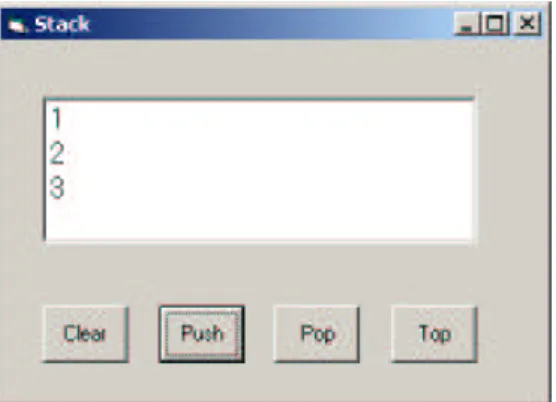
To better analyze this research work, all results use the same practical test case as reference. It is a Stack implementation, with frontend depicted in figures 1.7 and 1.8.
1.6
Document support
This document was written in LATEX [Lam94, Byn98, AAN03, Vic01], because of its
Figure 1.7: Stack implemented in Visual Basic
Figure 1.8: UIML stack rendered to Java
referred in this document, were formatted with styles of evdm, a LATEX Style [Oli02].
There is also a CD-ROM as complement of this work, which has all the resultant material used in this investigation, including source code and consulted bibliography.
Research Foundations
2.1
The context
Who gets faster the correct information and uses it properly, will leave winner
Don Keough1
The Software Engineering of today places emphasis on the need to systematize and to structure the processes of software development. Adopting more accurate methods (often identified as formal) or more or less structured processes, it is natural to find difficulties in the interpretation of the real need to transmit and to coordinate what must be executed, satisfying the expectations promised by the solution.
This can be compared with the scenario of a new house construction where, even if the projected architecture represents all the things to be built, it can only be certified at the end of the work. The same happens with our expectations in software design!
Referring essentially to the most recent terminology and concerns of the current software development techniques, we can list the following items:
• Fusion and Separation of concerns • Temporality on restricting interactions • MultiModal Interfaces [LFJ95, Ovi99] • Contents security
• Data hierarchies • Hypermedia contents
• Portability for multiple devices and platforms • Configured Visual Components
• Client/Server and X-Internet2
1President of American Coca-Cola. 2
X Internet - The X Internet pretends to be the future of applications, combining the advantages of centralized application deployment with the functional richness of locally installed software
• Web Services • Portals
• Inter-operability and B2B • Legacy Systems
This work, being specially focused with data Visualization in application inter-faces, it will give priority to the analysis of the existing technologies in the area. In [Pha00], Constantinos summarizes the main steps which one can identify in this pro-cess and, as the Seehein model [Pfa85] advocates, the importance on maintaining a real separation between the presentation layer and the remaining application layers.
Amongst the vast literature on HCI - Human Computer Interaction technology, published in the specialty journal e.g. Interactions, several annual conferences
-ACM3 SIGGRAPH Symp., Human Factors in Computing Systems, etc., the work of Martins [Mar95], Vijay [Mac96], Myers [MHP00] and Constantinos [Pha00] is
signif-icant.
2.2
User Interface Properties
”The User Interface (UI) is that part of a computer program that handles output to the display and input from the user. The rest of the program is usually called the application” [Mye95].
The complexity of this theme can be justified in many ways. Foremost among them is the difficulty in perfectly understanding tasks and users. One of the recommended solutions for this complex problems is the interactive design, although, this process still is, by itself, complex and prone to errors. It could be long and consequently expensive and difficult to identify the correct end of the interaction process. Next we present some desirable user interface [Mac96, Gee00] properties:
• Functionality. This refers to what an interface must perform. It must be defined before design and implementation.
• Usability. This deals with how good an interface is in satisfying its functionality, like promptness, ergonomic layout, performance, etc.[McE04].
• Isolation from Application. This is where the application must be isolated from the program user interface - Seeheim Model [Pfa85] - maintaining the inter-operability between the parts.
• Adaptiveness, Ability. Respond to different user profiles or program contexts,like
the recent Multimedia Skins (http://cs-skins.net) or CSS4[Gee00] .
• Consistency. Which facilitates the transfer of skills from one system to another. 3http://www.acm.org
• Standard. To assure consistency and portability.
User interfaces and almost everything around them have been called different names over the years. From UIMS, to Toolkits, User Interface Development
Environ-ments, Interface Builder Tools, etc., clearly merging tools with principles and concepts
[Mye96, Cyp93].
The authors of [JBK89] have also explored some system requirements for user interface development. They have concluded that most of the existing systems fulfill only some of those requirements. In Figure 2.1 (adapted from [JBK89]) we try to summarize the components of user interfaces. Although a slightly dated perspective (1989), we will see later on that it is still actual.
end user interface
dialog interface
database interface
application data dialog data
end user interface
presentation layer: physical presentation
presentation interface
virtual presentation layer: static UI aspects
internal virtual interface
virtual application layer: dynamic UI aspects
dialog interface
application layer: application functionality
Figure 2.1: The basic software architecture and the corresponding layered model for Human-Computer Interaction (adapted from [JBK89])
As we can see in Seeheim Model [Pfa85] and in [Mye96, MB86], and later on in recent architecture models (such as N-Tier [Mic04b]), there are evident concerns in separating responsibilities between interfaces and the rest of the application.
The functionalities are structured in layers as follows [Sch01]:
• Presentation layer: output to the screen; handling of input from the user; toolkit functionalities
• Virtual presentation layer: separation of input and output from the dialog; defi-nition of logical devices and virtual terminals; independent device presentation; handles all static aspects of the UI.
• Virtual application layer: this contains the semantics of the underlying applica-tion; dialog between the user and the applicaapplica-tion; handles all dynamic aspects of the UI.
• Application layer: main application’s functionality
2.3
User Interface Models
Let us go back in time and recall the “black box” architecture of the first software solutions, where the user could only use it and never try to change anything. So, it was difficult to use the same application in a new situation if not impossible. In our days the existing solutions are “broken” in several units, and behave like modules or components allowing modular interfaces.
Several models exist (and continue to be created) that can also be applied to User Interfaces [Mar95, Pha00]. A recent one was explored in Vadim thesis [Vad96], ex-perimenting automatic UI generation for applications. Also Markopoulos in [Pan97], describes important particularities for the main interface architectures and models. In the following sections, we will present the most significant ones, trying to demonstrate, by example, their particularities.
2.3.1 “Ancient” HCI models
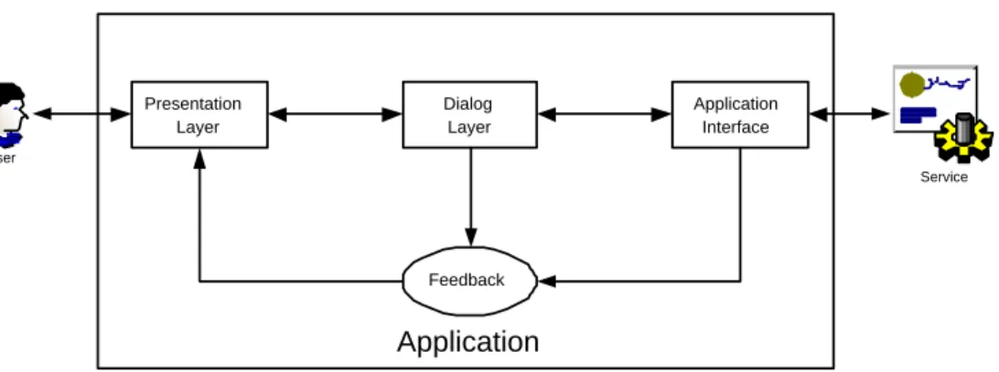
Several models have been proposed to describe UI and human-computer interaction. Perhaps the first and the most significant UI model was the one presented at the Seeheim Workshop in Berlin, in 1985 (thus the name Seeheim Model). Figure 2.2 de-picts its main particularities, where we can see clearly the separation between User
interaction and Application logic, using an UI split into three components. The Ap-plication Interface Model, which describes how and when methods in the apAp-plication
logic should be used (like semantic), the Dialog control, which is responsible for cor-rectly sequencing the dialog events (like syntactic) and the Presentation, which should “show” the interface (like lexical) to the user [Pfa85]. This “Compiler” mentality, tried to obtain, from Application Interface Model, a rapid semantic feedback.
Application Presentation Layer Dialog Layer Application Interface Feedback User Service
Figure 2.2: Seeheim Model
However, this logic and generic model was criticized and considered inadequate for current complex UI, because there are a lot of particularities that it does not take into account. Things like, for example, notations to use and information type to pass between components, are not present.
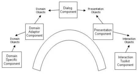
The same happened with the Arch model, specific for the run-time architecture of an interactive system, where, instead of examining the possibility to separate the pre-sentation from other parts, this model analyzes the nature of data that is communicated
between the user interface and the other UI components [Mig97]. Figure 2.3 depicts this model base architecture, where five components interact between them.
Figure 2.3: Arch Model
Those with an object oriented background, defend the idea of interfaces as collec-tion of objects, with a mechanism to pass informacollec-tion between components and related mechanisms. The idea was to minimize the effects of changing technologies, as sup-ported by object oriented characteristics [org92]. It works as a generalized Arch model but it does not support adaptive intelligent systems [Mig97].
The Triple Agent Model of HCI, with three components: Task Machine (applica-tion), User Discourse Machine (interface) and User, reflecting the human point of view over intended tasks, incorporating the strengths of previous models (integrated with
Arch model), becomes adequate for adaptive intelligent systems, like those supporting
IDSS5, supporting their multimodal interaction and dynamic presentation functionality
[Pue93].
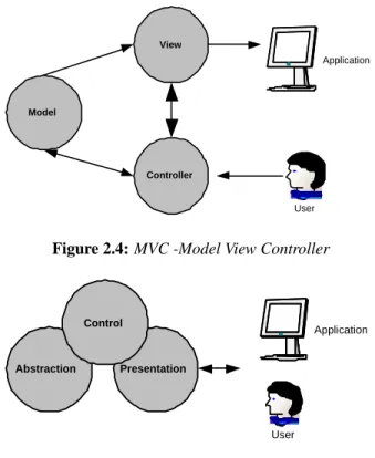
Believing that modern interfaces tend to be collections of quasi-independent agents (components as buttons, grids, etc.) hierarchically organized, and that inheritance, composition and aggregation are possible, the MVC - Model View Controller [KP88] (Figure 2.4) and PAC-Presentation-Abstraction-Control model [V´ıc96] (Figure 2.5), show how a single application abstraction could be multiply presented.
The MVC model divides an interactive application into three components. The model contains the core functionality and data. Views display information to the user. Controllers handle user input. Views and controllers together comprise the user inter-face. A change-propagation mechanism ensures consistency between the user interface and the model.
The PAC model defines a structure for interactive software systems in the form of a hierarchy of cooperating agents. Every agent is responsible for a specific aspect of the application’s functionality and consists of three components: presentation, abstraction, and control. This subdivision separates the human-computer interaction aspects of the agent from its functional core and its communication with other agents [Pue93].
Although not the most quoted in current UI development, these models represent 5IDSS - Intelligent Decision Support System
View
Model
Controller
User
Application
Figure 2.4: MVC -Model View Controller
Abstraction Presentation
User
Application
Control
Figure 2.5: PAC-Presentation-Abstraction-Control
the main results of previous research and the cornerstone of current mentalities. We shall see the “heritage” of these principles int the (current) models that are analyzed next.
2.3.2 XForms Model
XForms is the next generation of Web Forms [Rec03f]. It is based on XML [Rec03c]6
and, being a device independent description, it is intended to work with a variety of standard or proprietary user interfaces.
There is a standard set of visual components, which can be used in other markup languages, such as XHTML [W3C03], allowing interface description and form events handling. The input data is, naturally, represented in XML.
In this model, the interface is organized into three layers: presentation, logic, and
data. The data layer defines a data model for the forms (e.g., XML Schemas). The logic layer defines dependencies between fields. The presentation layer describes the
recent interface and the mappings to different devices [Pha00]. The main goals of XForms, can be enumerated as follows:
• Support for handheld, television, and desktop browsers, plus printers and scan-ners;
• Richer user interface to meet the needs of business; consumer and device control 6Appendix B summarizes XML technology
Proprietary User Interfaces WML XHTML Xforms User Interface Xforms Model Presentation Options
Figure 2.6: XForms architecture (adapted from [Rec03f])
applications;
• Decoupled data, logic and presentation; • Improved internationalization;
• Support for structured data forms; • Advanced forms logic;
• Multiple forms per page, and pages per form; • Suspend and resume support;
• Seamless integration with other XML tag sets.
As we can see, XForms is mainly concerned with inter-operability features, inte-gration needs and distributed cooperations. All these issues are associated with Web technology, going towards a standardization of using browsers as interface engines.
This model is particularly important for the work described in this thesis, as it provides a dialect to the widespread XML markup language used on user interface description. We will use XHTML to present our VDM-SL specification tests [IFA00c, Jon90].
2.3.3 The N-Tier Model
Although a recent model, the N-Tier model can also be considered in the context of the
Seeheim Model. Their principles are not very innovative and the scope does not offer
something particularly new, except for the fact of being suitable to Web technologies and web programming.
The main particularity of this model consists, in fact, on a clear separation of the application in several layers (or Tiers), as follows:
• Presentation Tier, typically a client web browser
• Dynamic Presentation Logic Tier, usually done in the Web server using many technologies (scripting, XML, Lets, etc.)
• Business Logic Tier, where all business objects and rules are implemented (using for instance Java Beans [Mic96]).
• Data Access Tier, which works as a wrapper around data repositories (relational databases, flat files, etc.)
• Backend System Integration Layer (often named Data Tier) which consists of a distributed set of relational databases, integrated with the middle tier using specific technologies (ex. JDBC [Mic03d]) as well as other legacy systems. Figure 2.7 represents a distributed N-Tier model and current support technologies and applications.
Client
(in remote browser station)
XSL/CSS DXHTML/Flash
Lets/ActiveX
Presentation
(in Web container)
XMLServlet, Servlets,JSP, ASP.Net
Business Logic
(in Application container)
EJB,JMS,JINI Web Services
.NET
Persistence
(in Database and/or Legacy Systems)
XML JDBC, .NET ODBC
JavaSpace
Distributed N-Tier Model
Figure 2.7: N-Tier Model
This model will be further explored in section 2.6.2, where we discuss the N-Tier
architecture used in the Microsoft .Net architecture, in the J2EE Sun platform [Mic04c]
and in the Intel e-Business [eBC01] platform.
2.3.4 MIM Model
MIM is an abbreviation of Meta-Interface Model which extends the level of abstraction
of the Slinky model [org92]. MIM was created with the proper abstractions to describe interfaces that can map into multiple and distinct types of devices [Pha00].
We include the description of this model here, because it is the basis of the markup specification language used in this work to describe user interfaces: the UIML [Pha00, V¨og03].
MIM divides the interface into three major components: presentation, logic, and
interface, the last one being divided into structure, style, content, and behavior, as
depicted in Figure 2.8. Interface Presentation Structure Style Content Behavior Logic Peers Device/Platform UI Metaphors Applications/ Data Sources
Figure 2.8: Meta-Interface Model (adapted from [Pha00])
The logic component provides a canonical way for the user interface to commu-nicate with an application, while hiding information about the underlying protocols, data translation, method names, or location of the server machine.
The presentation component provides a canonical way for the user interface to render itself, while hiding information about the widgets and their properties and event handling.
The interface component describes the dialogue between the user and the applica-tion using a set of abstract part, event, and method calls, that are device and applicaapplica-tion independent.
Based upon the MIM model and able to describe generic interfaces that map into multiple distinct devices connected to a wide range of application technologies, is the
UIML 2.0 [AH00], markup specification language for generic interfaces (see section
3.4 for a UIML description, providing more detailed information on this matter).
2.3.5 Other research in HCI modelling
HCI [Pan97] is a dynamic area of research. Recent studies describe important results which are briefly reviewed below.
[Reh01a] revealed the fact that a lot of these applications violate basic HCI guide-lines such as Norman’s design principles [Pop01]. More specifically, developers often leave the user with too little control, do not provide appropriate feedback about what the system is doing and fail to show appropriate constraints to the user [KR02, Nun01]. In [Reh01b], Kasim argues that, founded on the principle that “every object has an output”, there is the continued possibility to work on new user interfaces models, connecting the real to the virtual world with a VDU - Visual Display Unit.
Another interesting point of view was presented in [JFMdM92], where Baar shows the importance of “coupling” application design and user interface design. The main argument is based on spending less time and effort on the development process, avoid-ing the risk of buildavoid-ing similar but not identical specifications duravoid-ing the development process. In his opinion, the data model and user interface design may have a lot in common, including objects, actions and attributes (and quite often, rules).
Recently, Geert in [Gee00] explored some formal modelling techniques in Human-Computer Interaction, trying to evaluate these techniques according to the main UI principles: completeness, applicability, validity and usability.
A recurrent theme is the possibility of automatically generating some user inter-face parts (like direct forms) related to some database relations. There are already some “engines” which work as “extractors” to some different representations (for ex-ample XML) of all data model information, notably the Database-to-XML mapper from Altova (http://www.altova.com).
Not completely disagreeing with these perspectives, we hope to contribute within this work area to clarify some nuances and give some input to this cycle of continuing development.
Trying to focus on the main goals of this work, we will approach the three main phases of the user interfaces development process for computer applications, involving models structured or not:
• The Specification, which should provide the definition of what one intends to do • The Design, which should provide the representation of intended results • The Interface Programming which should provide the execution of the final
work, the Interface.
2.4
User Interfaces Analysis and Specification
”User Interfaces are considered as one of the six core fields of Computer Science and are regarded as the most critical area for organizational impact” [Mac96]
Any programmer does, even as a reflex of a memory exercise, a specification of what he intends to execute. So, to specify can simply mean to opt.
Supported in more or less certified methods, rebounding or not the user interaction during analysis, the verification or not of application interfaces, often referred to as Legacy Systems, it will result in something that will support later phases of the devel-opment process. This phase is usually called Specification, Prototyping, SRS - Sheet
of Requirements Specification, etc.
Problems arise in this initial phase because programmers have to cope with the complete definition of a final application, including user interfaces and everything to support it (e.g. storage information, integration rules, etc.). Any rigidness applied to these processes can be harmful. Even more, development teams are often constituted by only one person.
References [Mye96, Mac96], describe several options to archive UI specifications. Here we refer two of them which are actually very common and essentially related with the main goal of this work: Application Frameworks and Interactive Specification.
• Application Frameworks, like the older X-Windows API or the recent Visual
Studio .Net [Mic04b] and J2EE [Mic04c], allow programmers to develop UI by
abstracting from the underlying platform. This means to work on program inter-faces (and other parts) and have the same aspect in multiple platforms, allowing some customization features.
• Interactive Specifications, often called Direct Manipulation [Shn97] (we will go back to this later on section 2.4.2), allow programmers to develop UI by manip-ulating objects on screen, using pointing devices. In this group we can include
prototyping tools, like the recent visual tools (PowerDesigner from Sybase,
Code-Warrior from MetroWorks, etc.), Wizard tools, etc., which allow assisted inter-vention on developing particular interfaces (based on forms, grids, etc.), like recent Visual Studio .Net in C# or Visual Basic .Net languages, and Graphical
Editors which enable, in a way, to develop an interface from a library of
exist-ing components (like DLL, OCX, Java Beans, etc.) and, in another way, some important particular features used on debugging processes, data analysis, etc. We should refer here the Microsoft OLAP Cube component which offers, for instance, Data Warehousing features.
In the recent technology evolution, Remote Process and Peer-to-Peer7 solutions
are crucial elements in the development process. So a new complement to describe Interactive Specification needs to be considered. We also need to consider new impor-tant features for the programmers, allowing them to have their widgets library, some of those remote components which should “work” in his computer. We are talking about
Web Services8, for instance.
Proceeding with our review, it is now important to describe more accurately some common technologies or processes to carry out UI development. As mentioned when listing the main goals of this work, it is important to focus on formal methods and related technologies in this process, thus preparing for its exploration in the context of this work.
2.4.1 Adaptable Interfaces
We already know that the User Interface (UI) allows the user of the software system to interact with it. Being itself a kind of software system, with similar development processes as other application types, it has a set of attributes or requirements - called
Non Functional Requirements (NFR in [Lec99, SC03], such as usability, reliability,
simplicity, ergonomics, etc. [Mye95], very hard to measure or to classify). Adaptabil-ity is perhaps the most worrying property, due to the recent need to support several emerging new devices.
7http://www.openp2p.com 8
Adaptation can be seen as the capacity of a system to react against changes in its environment, which, as in almost all software systems, will be possible only if its support architecture is also adaptable.
There are several studies in this area and some application solutions which deal with this. We focus our attention on two of them. The first one is the XXL/XIBuild [Lec96], an interactive Interface Builder based on Visual Programming. It is supported by a particular specification language and allows for automated building of a graphical user interface, easily converted to C/C++ code. It can represent all the interface in text view (source code), graph view (abstract iconic in Figure 2.9) or widget view (graphical user interface), where all user interaction will take place. We are talking about Motif widgets9and all adjacent rules and conditions10.
Figure 2.9: XXL/XiBuilder Visual Builder Graph View
The second one that deserves our attention is SA3 [SC03], where these concepts are well explored, having resulted in a definition of adaptability as described in the following paragraph:
“adaptation of a system (S ) is caused by change (δE) from an old environment (E ) to a new environment (E0), and results in a new system (S0) that ideally meets the needs of its environment (E0)” [SC03]
So, mathematically Adaptation is defined by the following finite function: Adaptation: E × E0× S → S0, where meets(S0, need (E0)) 9
http://www.motifdeveloper.com/widgets.html
10
where the Figure 2.10 explains the relationship between the various symbols de-scribed above. S E E’ S’ meets meets S E
Figure 2.10: Explanation of symbols in the definition of adaptation (adapted from [SC03]) From our point of view this behavior of reacting to environment changes reflects the recent orientation of any one who worries with user interfaces. Putting a particular application (legacy or not), available on Web support, on mobile devices via WAP, etc., translates this kind of interaction over existent interfaces. We are also convinced that several adaptations on user interfaces of recent applications are made from the scratch or result from traditional ad hoc development, without any model-based approaches [FF93, BVE02, VBS01].
Later in this thesis we will show that these adaptations can be done in a systematic way following rigorous methods and mechanisms. We must always be sensitive to the fact that “to find the best component to use in a particular situation” is be a delicate process.
2.4.2 Formal Methods and Specification
“Formal techniques have a defined syntax and semantics and therefore ambiguity is completely eliminated” Andreas Gerstinger”[Ger01]
Among many definitions in the literature of a “formal method”, we chose the one provided by the largest professional organization promoting the use of formal methods - FME - Formal Methods Europe [FME03]:
“Formal Methods are mathematical approaches to software and system develop-ment which support the rigorous specification, design and verification of computer systems.”
2.4.2.1 Why are they not used more widely?
Andreas Gerstinger presents (in Chapter 2 of [Ger01]) an interesting overview about formal methods, considering their foundations, classification and application criteria, as well as the main particularities of common formal languages. This contributes to highlight their numerous potential benefits.
However, there are a lot of assumptions which “delay” the application of this kind of methods. Anthony Hall, in ”Seven myths of Formal Methods” [Hal90], on the
appli-cation of a formal method (Z) to a large real problem, puts forward seven unjustified stereotypes and refutes each one of them:
1. Perfect software results from formal methods 2. Formal methods mean program proving
3. Formal methods can only be justified for safety-critical systems 4. Formal methods are for mathematicians
5. Formal methods increase development costs 6. Clients cannot understand formal specifications
7. Formal methods have only been used for trivial systems.
On the one hand, Hall moderates overly optimistic “myths”, such as “formal meth-ods can guarantee that programs are correct”. On the other hand, he argues that formal methods do not involve complex mathematics, do not increase the cost of development and are not incomprehensible to clients [Ste99].
Working on this cause, Brad Myers in [MHP00] comments on the unaccomplished application of formal languages to UI development tools. As many other (formal or in-formal) approaches like Transition Diagrams (mainly on Structure Analyzes), Parsers for Context Free Grammars, etc, they looked very promising at first, but they did not catch on for several reasons. Most of them are pointed out as a topic for future work.
There seems to be a lost opportunity, because the excellent work on using formal languages for dialog based interfaces, was surmounted by interface styles based on
Direct Manipulation [Shn97], which have emerged meanwhile. Another reason could
be related to the difficulty to represent them using unordered operations (like Set oper-ations), by contrast, they can easily be represented using sequences. So, the interfaces should naturally appear with a rigid sequence of operations.
And last, the need to learn a new programming paradigm, putting the program-mer against the need to understand new programming concepts, is a hard obstacle to overcome.
2.4.2.2 Archetype: the necessary proof?
[MO85, Mar95] present an important step in reinforcing the application of formal methods in software development. These works appeared on technological scenarios where more rigorous mechanisms on defining entities, processes and their interaction in graphical systems (and, in consequence, in user interfaces) became an important demand.
They purport the idea of having, for each system, objects one has to work with, and a corresponding object for its visualization. These visualization objects are like semantic graphical representations [Mar95].
Object construction, a common operation in practically all interface “builders”, induces the creation of standard abstract objects which could represent the same and
![Figure 2.1: The basic software architecture and the corresponding layered model for Human- Human-Computer Interaction (adapted from [JBK89])](https://thumb-eu.123doks.com/thumbv2/123dok_br/17962621.854506/29.918.215.663.335.575/figure-software-architecture-corresponding-layered-computer-interaction-adapted.webp)
![Figure 2.6: XForms architecture (adapted from [Rec03f])](https://thumb-eu.123doks.com/thumbv2/123dok_br/17962621.854506/33.918.324.549.91.402/figure-xforms-architecture-adapted-from-rec-f.webp)
