Dealing with dynamic security due to reversible
hydro power plants in islanded power systems
A study case for increasing renewables integration
M. H. Vasconcelos
1,2, P. Beires
1, C. L. Moreira
1,2, J. A. Peças Lopes
1,21Instituto de Engenharia de Sistemas e Computadores – Tecnologia e Ciência (INESC TEC) 2Faculdade de Engenharia da Universidade do Porto (FEUP)
Porto, Portugal
[email protected], [email protected], [email protected]
Abstract— In this paper, the dynamic security analysis of a
real islanded power network is performed, comprising the future installation of a reversible hydro power plant in order to increase renewable energy integration. Being a high-head facility, this hydro power plant will include Pelton hydro turbines. Due to economic reasons, the adopted water pumping technology will consist in fixed speed hydro pumps directly connected to the grid. Based on extensive numerical simulations of the power system’s dynamic behavior response, it was possible to conclude that the role of the hydro power turbines for the purpose of the grid stability conditions is marginal and that additional measures are necessary in order to avoid dynamic security problems in this islanded power system. With this study, it was possible to observe that, although the foreseen operation of the reversible hydro power plant may create new security challenges to overcome, a robust technical solution can be found dealing with the new constraints without increasing the operation complexity of the power system.
Keywords— reversible hydro power plants; Pelton turbines; fixed speed hydro pumps; dynamic security; islanded power systems; renewable generation.
I. INTRODUCTION
Integration of large shares of time variable renewable generation, like wind power, in islanded power systems may become a difficult task due to the need to ensure adequate frequency regulation capabilities, which is traditionally achieved by means of synchronous thermal units. The minimum technical requirements for the operation of such units may lead to the spillage of renewable generation during valley hours unless storage solutions, either based on batteries or via reversible hydro generation, are used [1]-[5]. If adopting a battery based solution, this also allows the provision of fast frequency control. However, when the amount of energy to be transferred from valley hours to peak hours is large this solution becomes quite expensive.
In some islands, orography and climatic conditions allow the construction of reversible hydro power plants (sometimes involving the construction of artificial upstream and downstream reservoirs). In these cases, this becomes the most suitable energy storage system to use [6], taking into consideration the associated head, larger storage capacity and
round-trip efficiencies. In fact, for power system sizes of a few MW and beyond, this constitutes the most technically mature and economic viable alternative [7]. During valley conditions, the surplus of renewable power production is stored, by using the reversible hydro power plant in pumping mode. In peak hours, the energy stored through water pumping can be recovered by the hydro turbines to replace expensive peak generation.
However, large scale integration of renewable power generation is not a simple problem to handle in autonomous power systems, like islands. Adequate spinning reserve values and frequency regulation capabilities must be always ensured, being traditionally provided by thermal units. In order to increase renewable power production in these power systems without jeopardizing system security, it is crucial to perform dynamic behavior studies to evaluate if extra measures need to be implemented in these power systems.
In fact, in isolated power systems, a critical factor is the time response of primary frequency control systems. The trip of a generator will provoke a quick fall of system frequency, requiring a fast power injection to avoid load shedding. On the other hand, a sudden load loss, which can be caused by the tripping of pump units in the reversible hydro power plant, may create a shortfall of negative spinning reserve. Such adverse operating conditions may lead to the reversion of the active power flow direction in the thermal machines that are providing secondary frequency control and, consequently, to the tripping of these machines by the associated reverse power flow relays.
In order to obtain considerable installed capacities, and when the local orography allows it, hydro power plants in these power systems are usually high-head facilities. In high-head hydro pumping storage projects, two different types of hydraulic machines are usually adopted – Pelton turbines and high pressure pumps – coupled to synchronous and asynchronous machines respectively [6]. In particular, the use of fixed speed pumps directly connected to the grid through induction motors is exploited, due to their reduced cost and improved efficiency conditions for the machine’s designed speed. However, some technical limitations are introduced by adopting such a configuration:
The usage of Pelton hydro turbines for frequency regulation is limited by the high water starting time resulting from the high-head hydraulic circuit (due to the effects of water inertia, water compressibility and pipe wall elasticity in the penstock [8]), and by the large value of the injectors’ opening time, adopted to avoid transient pressure problems in the penstock [6]. The adoption of fixed speed induction motors for water
pumping may lead to their sudden disconnection when faults take place in the system, following the operation of their minimum voltage protection, due to the propagation of the residual fault voltages.
So, a large presence of reversible hydro generation stations, for increasing the integration of renewables in isolated power systems, may create critical stability issues. On the one hand, a deficit of fast-acting positive spinning reserve in hydro turbines arises due to its limited power response capability. On the other hand, in valley operating scenarios with a large load imposed by fixed speed hydro pumps, the occurrence of a short-circuit may lead to the sudden loss of this consumption, which may afterwards cause a shortfall of negative spinning reserve and the consequent tripping of the thermal generation units.
In this paper, these stability constraints are evaluated for a real isolated power system of a European Atlantic Island, where a high penetration of renewable power production is expected to be in operation together with a reversible hydro power plant. Based on extensive numerical simulations of the power system’s dynamic behavior response, a robust technical solution was found by setting appropriate spinning reserve margins, defining a shedding strategy for the hydro pumps and managing the transient response capabilities of the wind generation, in order to deal both with the deficit of negative spinning reserve during valley conditions and the deficit of fast-acting positive spinning reserve.
This paper is structured as follows: first, the adopted stability study formulation is presented in Section II; then, Section III describes the study case and the analysis of simulation results obtained for this power system; finally, Section IV presents the main obtained conclusions of the performed analysis.
II. STABILITY STUDY FORMULATION
In modern islanded power systems, ensuring system security and robustness usually involves no load shedding. So, in the stability study formulation, the security criteria must be the following: none of the foreseen disturbances must provoke automatic frequency load shedding situations.
Foreseen disturbances usually comprise an N-1 contingency, like a power unit loss, or the consequences of a three-phase short circuit located in some of the transmission lines or distribution feeders.
The dynamic stability studies to be performed should be focused on scenarios with extreme (worst case) operating conditions from the perspective of the dynamic stability/frequency control. By ensuring security for these extreme scenarios, system security will be guaranteed for all
scenarios. By following this approach, two extreme operating scenarios must be evaluated: (a) a valley scenario with maximum pumping power consumption and maximized renewable power generation; (b) a peak scenario with maximized renewable power generation including the hydro production from Pelton turbines.
In an extreme valley scenario, all the hydro pumps are assumed to be connected at rated power, to maximize renewable power production without violating the technical constraints of thermal dispatch (i.e., minimum number of connected units and spinning reserve criteria). This valley scenario provides the extreme conditions in terms of having sufficient: (a) fast-acting positive spinning reserve, after a power unit loss; (b) negative spinning reserve for the sudden loss of pumping units, after a short-circuit.
Aiming to reduce the time needed to generate active power in Pelton turbines and to improve system inertia, these units can be operated in a no-flow mode during valley scenarios, while its generator is synchronized with the power system in synchronous compensation mode (i.e., performing voltage regulation with no-load), being therefore ready to inject active power if required [6]. Following the occurrence of a sudden event in the electric power system, requiring the response of the hydro turbines under a frequency sensitive regulation mode, a suitable design of the hydraulic circuit must be performed in order to allow the proper reaction of the hydro turbines. As it is proposed in [6], the most favorable technical option requires the installation of two separated penstocks (one dedicated for the turbines and another for the pumps). The adoption of such solution increases the overall cost of the system but contributes for the maximization of the turbines’ frequency response capabilities in the no-flow mode during valley hours. Therefore, taking into account the dynamic performance of the island’s power system during valley periods, it is necessary to decide on investing in independent penstocks for the Pelton turbines and pumps. Such evaluation requires a dynamic stability analysis of the system in which the technical benefits provided by this configuration, as a result of the improved regulation capabilities of the Pelton turbines, must carefully be quantified.
In an extreme peak scenario, all the exogenous renewable power production is assumed to be dispatched, and the reversible hydro power production is maximized without violating the technical constraints of thermal unit’s dispatch. Since no pumping is taking place, Pelton turbines can operate in frequency regulation mode even if a single penstock is to be installed. This peak scenario provides the extreme conditions of maximum renewable power production.
For isolated power systems having a major integration of wind power production, the post-disturbance transient period after a short-circuit can be critical. In fact, even modern wind generator devices with advanced grid functionalities (namely fault ride through capabilities) face a severe active power reduction in the moments subsequent to the fault, which is then followed by a ramping period in order to recover the power production to the pre-fault value [9].
Since in peak scenario there are no pump units in service, during a short-circuit the loss of wind production cannot be
counterbalanced by the tripping of pumped units. Therefore, the defined peak scenario provides the extreme conditions in terms of having enough fast-acting positive spinning reserve to compensate the loss of wind power in the event of a short-circuit.
III. STUDY CASE
A. Power System Description
The power system analyzed for this study is located on a medium size island, in the European Atlantic Ocean. Thermal power generation is provided by ten diesel units, with an installed capacity of approximately 4x2 + 4x5 + 2x11 MW. Wind power production is provided by two wind parks, comprising ENERCON variable speed synchronous generators and having an installed capacity of 10x0.9 MW and 4x0.9 MW respectively. A waste-to-energy power unit of 2 MW is also connected to the grid and the installation of a geothermal power plant of 3.5 MW is under study for a close future. For the period under analysis, the expected off-peak load is around 15 MW, during the night, and the peak load is near 32 MW.
Aiming to maximize renewable energy production in the island, a reversible hydro power plant is expected to be in operation comprising: (a) a Pelton turbine coupled with a synchronous generator with a rated power around 7 MW; (b) six fixed speed hydraulic pumps, each one driven by a squirrel cage induction motor with a rated power of 1.25 MW.
Automatic voltage regulation (AVR) is assumed to be performed by the diesel, geothermal, hydro turbine (when in operation) and waste-to-energy units. The provision of spinning reserve and automatic frequency regulation is supposed to be performed by diesel generators and, hypothetically, also by the hydro turbine. For the provision of negative spinning reserve, diesel units are assumed to be connected to the grid while there is no reversion of the active power flow. Therefore, in each instant, the amount of fast negative spinning reserve is defined by the diesel power production.
In the analyzed power system, the technical constraints for the dispatch of the diesel generators are defined as follows: (a) a minimum number of two diesel units must be connected to the grid, comprising a large and medium size generator; (2) a minimum thermal spinning reserve value should be assured in order to outbalance the loss of half the total renewable power infeed from wind, geothermal and waste-to-energy units.
B. Adopted Dynamic Model
In order to perform dynamic simulations for this power system, MATLAB® Simulink® was the chosen simulation
software platform, using Simscape Power SystemsTM
component libraries. The considered parts of the grid’s topology comprise the power plants and the transmission system (established at the 30 kV voltage level). The most important elements of the grid were modelled as follows:
1) Diesel power plants
These units were represented by a synchronous machine with mechanical power controlled by a governor. This
governor comprises both proportional and integral control, providing primary and secondary frequency regulation respectively. The engine response was represented by a first order transfer functions representing the inherent response delays. Maximum and minimum output torque restrictions were also taken into consideration. In terms of voltage control, these units were equipped with an AVR, using a custom-designed IEEE Type 1 exciter model.
2) Geothermal and waste-to-energy power plants
The ability of geothermal and waste-to-energy power generation facilities to provide active power modulation in a useful time gap is nearly inexistent. Therefore, the adopted model was a synchronous machine with constant mechanical power input. AVR was also included, using the previously mentioned IEEE Type 1 exciter model.
3) Wind power generators
The considered model for wind generators is intended to represent the response of the units with respect to the grid rather than the full dynamics of its main building blocks. Therefore, in order to consider a proper model for the ENERCON variable speed synchronous generators, the key functionalities regarding their behavior during faults was considered. For very severe faults (voltage at the terminals of the machine below 0.2 pu), the Zero Power Mode (ZPM) allows these wind generators to remain connected to the grid but not feeding any active and reactive power. For less severe faults (with voltage sags in the range of 0.2 to 0.9 pu), the ENERCON technology provides another Fault Ride Through (FRT) mode - the PQ control mode. This mode consists in maintaining the active and reactive current injection equal to the pre-fault values during the fault, being this the operation mode defined for the wind farms installed in the electric power system under study. As a consequence of this behavior, during a fault active and reactive power will be reduced as a result of the voltage dip at the generator terminals. After faults, the active and reactive power recovery is limited by a maximum gradient [9].
4) System load/distribution feeders
As previously mentioned, the detailed modelling of this power system only involved the transmission system in 30 kV and power plants. All loads are considered as constant impedances connected downstream of distribution transformers.
5) Voltage and frequency protection systems
One of the main criteria to evaluate the system security is the absence of load shedding. The local system operator implement voltage and frequency relays in substations in specific feeders as a security measure to face severe situations. However, dynamic studies are intended to validate solutions that ensure the continuous power supply of the grid’s customers. In the dynamic model, it was therefore necessary to flag the action of the most sensitive load shedding relays in order to take into account the possibility of occurrence of load shedding, which is the driving concern with respect to the system security criteria.
Additionally, the hydraulic pumps in the reversible hydro power plant are driven by induction engines, which are very
sensitive to voltage dips. This implied that voltage relays had to be modelled, in order to trip the pumps if voltage drop below a certain threshold.
6) Reversible hydro power plant
The reversible hydro power plant was represented by a separate modelling of their pumps and turbine. As previously mentioned, pump units are represented by conventional induction machines whose reactive power consumption is compensated by nearby capacitor banks. With respect to the hydro turbine and associated control system, a modelling approach with the explicit inclusion of the following three main components was adopted [8]:
Turbine and hydraulic circuit: being represented by a linearized fourth-order model with elastic water column, thus taking into consideration the water starting time as well as the wave travel time in the penstock; Speed governor: modelled by a
proportional-integral-derivative controller, driving the opening position of the water injectors in the Pelton turbine (the controller model also integrates the opening limits of the water injectors as well as its opening speed);
Hydro generator: represented by a salient pole synchronous machine (sixth-order model, including transient and subtransient flux behavior).
The characteristics associated to these components are summarized from Table I to Table III.
TABLE I. PELTON TURBINE AND PENSTOCK
Turbine rated power 7 MW
Penstock length 2370 m
Penstock diameter 1.1 m
Water volume flow 2.4 m3/s
Water starting time with inelastic water column (Tw) 1.8 s
Wave travel time (Te) 4.74 s
Hydraulic head 340 m
TABLE II. SPEED GOVERNOR
Total opening time of injectors 15 s
Integral gain (Ki) 1.2 pu
Proportional gain (Kp) 1 pu
Integral control time constant (Ti) 2.5 s Derivative control time constant (Td) 1 s
Filter time constant (Tf) 0.2 s
TABLE III. HYDRO GENERATOR
Rated apparent power 9 MVA
Rated voltage 6.3 kV
Inertia constant 1.43 s
C. Analysis of Simulation Results 1) Valley scenario
The generation/consumption conditions of the defined valley scenario are presented in TABLE IV. For these operating conditions, the most severe power unit loss disturbance regards the tripping of G10 diesel unit, leaving the system with just 2.5 MW of fast-acting diesel spinning reserve after a 5.1 MW generation loss. As it was previously discussed, in the development of the dynamic simulation studies two different situations were considered. In a first case, a situation
accounting for the use of two separated penstocks was considered, thus allowing the hydro turbine that was operating in the no-flow mode to provide some power-frequency control capabilities in the moments subsequent to the disturbance. Complementarily, a second situation was also considered where a single penstock is used (in this case, the no-flow operation of the turbine is also considered, but no power-frequency regulation capabilities are attained in this case).
TABLE IV. VALLEY SCENARIO
Generation Pg [MW] SR+ [MW] Consumption Pc [MW] hydro turbine 0 7 Load 15.1 diesel G8 2.5 2.5 Pumping 7.5
G10 5.1 5.4
geothermal 3.5 - Legend
wind park 1 7.5 - Pg: active power generation
wind park 2 3 - SR+: positive spinning reserve
waste-to-energy 1.4 - Pc: active power consumption
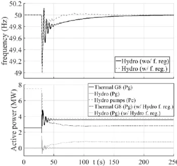
The dynamic simulation of this situation showed that the frequency regulation capabilities provided by the reversible hydro power plant (offering 7 MW of spinning reserve) is limited, having a negligible influence in the first seconds after the disturbance. Therefore, it was necessary to consider the installation of an under-frequency shedding mechanism for the hydro pumps in order to avoid the activation of load shedding of the other loads of the grid. Under-frequency shedding of the hydro pumps constitutes a resource that acts favorably in order to quickly provide an extra amount of fast-acting positive spinning reserve required for this disturbance.
Fig. 1 presents the obtained dynamic simulation results for this described situation, were three hydro pumps were automatically shed when frequency reached 49 Hz (i.e., a frequency drop of 1 Hz relative to a nominal frequency of 50 Hz). This measure avoided load shedding in the power system.
Legend: f. reg – frequency regulation; Pg – active power generation; Pc – active power consumption.
Fig. 1. Dynamic simulation results for G10 loss, in valley scenario, including an under-frequency relay shedding strategy for the hydro pumps, with/without frequency regulation provided by the hydro power turbine.
Fig. 1 also illustrates the negligible influence of the hydro turbine providing frequency regulation in the first seconds after the disturbance. Therefore, the reduced dynamic regulation capabilities of the hydro turbine, as a result of the long penstock they use, points towards the possibility of using a single penstock in the reversible hydro power station.
Regardless of the scenario under analysis, a fault situation in any of the transmission lines will provoke the tripping of all the connected fixed speed hydro pumps, due to a severe voltage dip. In the defined valley scenario, after the post-fault active power recovery from the wind parks (after picking up from a ZPM situation), the power system will face a severe load loss of 7.5 MW (i.e., the hydro pumps consumption), comprising just 7.6 MW of diesel negative spinning reserve to provide frequency regulating actions. As presented in Fig. 2, this leads to a limit situation. Although is does not create a major impact on system frequency transient behavior, it may lead to a reverse power flow condition in the diesel units and, consequently, to the tripping of these units followed by the overall system collapse.
Legend: Pg – active power generation; Pmec - mechanical power; Pc - active power consumption.
Fig. 2. Dynamic simulation results for a fault in a transmission line, in valley scenario.
To avoid the previously described situation, the spinning reserve criteria of this power system must always include enough negative spinning reserve in diesel units to compensate the sudden loss of the connected fixed speed hydro pumps. Assuming that diesel units are able to operate with reduced power production for a few minutes, from the dynamic behavior studies’ perspective, the following minimum spinning reserve criterion was found to be suitable for this power system:
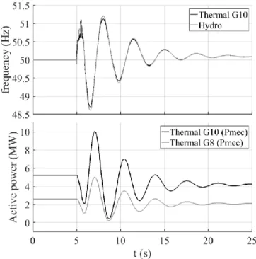
kPc,pumping Pg,diesel, with k ≥ For the same valley scenario, the most severe location for a three-phase short circuit is in the beginning of the most loaded distribution feeder. This will cause the tripping of all the connected hydro pumps (due to a voltage dip) as well has the loss of the faulted feeder (due to protection systems’ action to isolate the fault). After the wind parks active power recovery (after picking up from a PQ control mode situation), the power system will face the most severe load loss, consisting of 9 MW (7.5 MW from the pumps and 1.5 MW from the feeder). Being the 7.6 MW of available negative spinning reserve insufficient, additional measures were necessary to deal with this possible deficit of negative spinning reserve during valley conditions. Dynamic simulations showed that, for this power system, an efficient technical solution consists in adopting an over-frequency relay for the largest wind park (wind park 1), by automatically disconnecting this facility when frequency reaches 51 Hz. The dynamic simulation results, obtained by adopting this strategy for the valley scenario after a fault in the most loaded distribution feeder, are presented in Fig. 3 and Fig. 4. From these results, it was possible to conclude that the proposed over-frequency relay tripping strategy avoids the reverse power flow condition in all the diesel units, being therefore most suitable for this power system.
Fig. 3. Dynamic simulation results for a fault in the most loaded distribution feeder, in valley scenario, including an over-frequency relay shedding strategy for wind park 1 (1/2).
Fig. 4. Dynamic simulation results for a fault in the most loaded distribution feeder, in valley scenario, including an over-frequency relay shedding strategy for wind park 1 (2/2).
2) Peak scenario
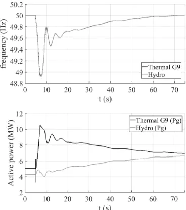
The generation/consumption conditions of the defined peak scenario are presented in TABLE V. In this case, the hydro pumps are not in operation and hence the connected hydro turbine can provide some frequency regulation capability. For these operating conditions, there are no situations with deficit of fast-acting spinning reserve after a power unit loss disturbance. The most severe situation for this type of disturbance involves the tripping of one of the diesel power units, leaving the system with 5.5 MW of fast-acting diesel spinning reserve after a 5 MW generation loss. The dynamic simulation results obtained for this situation are presented in Fig. 5, showing that the power system is able to ensure dynamic security by not leading to load shedding situations.
TABLE V. PEAK SCENARIO
Generation Pg [MW] SR+ [MW] Consumption Pc [MW] hydro turbine 4.3 2.7 Load 32.1 diesel G9 5 5.5 Pumping 0
G10 5 5.5
geothermal 3.5 - Legend
wind park 1 9 - Pg: active power generation wind park 2 3.6 - SR+: positive spinning reserve waste-to-energy 2 - Pc: active power consumption
For the same peak scenario, a three-phase short circuit in any of the transmission lines leads to a temporary but severe active power reduction in all the connected wind generators, since they will enter in the ZPM control mode as a result of the short-circuit voltage sag. Since in peak scenarios the loss of wind production cannot be counterbalanced by the tripping of pump units, this type of disturbance may create a temporary deficit of fast-acting positive spinning reserve. In the analyzed extreme peak scenario, this disturbance leads to a temporary generation loss of 12.6 MW (due to having the wind parks in ZPM) for a fast-acting diesel spinning reserve of 11 MW. As presented in Fig. 6, again the frequency regulation capabilities provided by the reversible hydro power (offering 2.7 MW of spinning reserve) proved to be limited, not being able to avoid load shedding in the first seconds after the disturbance.
Fig. 5. Dynamic simulation results for G10 loss, in peak scenario.
Fig. 6. Grid frequency obtained from simulating a fault in a transmission line during the peak load scenario.
Given the aforementioned results, extra measures were necessary in order to avoid load shedding and hence assure the fulfilment of the defined security criteria. For this power system, time domain simulations showed that load shedding can be avoided by increasing the value defined for the maximum active power recovery gradient in wind generators, after a FRT situation. However, such adjustment that is required for the specific case of peak scenarios will decrease the system security margin during faults in valley conditions, where the security problem is a result of the deficit of negative spinning reserve. Therefore, when adjusting the new value for the wind active power recovery gradient after a FRT situation, it is necessary afterwards to look for a new robust solution.
The dynamic simulation results, obtained for the peak scenario with the new considered value for the wind park
active power recovery gradient, are presented in Fig. 7. Comparing with the results described in Fig. 6, it is possible to observe that the new adjusted value for wind active power recovery after a fault was able to contain the frequency drop, thus avoiding load shedding situations in this power system.
Fig. 7. Dynamic simulation results for a fault in a transmission line, in peak scenario, including an increased maximum active power recovery gradient in wind generators after a FRT situation.
3) Technical solution robustness validation
To illustrate that the increase of the wind farm active power recovery gradient identified for the peak scenario is robust to be applied in any scenario, Fig. 8 presents the obtained results when applying this solution in the valley scenario. By comparing it with the results presented in Fig. 4, it is possible to observe that by increasing the maximum wind power recovery gradient after a FRT situation, the distance for the diesel units to reach a reverse power flow situation also decreases. However, this limiting situation is not reached and therefore no security problems are created by the additional measure found previously for peak scenarios.
On the other hand, adopting an over-frequency shedding strategy for wind park 1, required for scenarios with connected hydro pumps, may create unnecessary wind power disconnections in the power system (as in the peak situation described in Fig. 7). Therefore, to minimize wind power disconnections, the adopted over-frequency relay shedding strategy in wind parks should be operational only during scenarios where hydro pumps are in operation.
Fig. 8. Dynamic simulation results for a fault in the most loaded distribution feeder, in valley scenario, including an over-frequency relay shedding strategy for wind park 1 & an increased maximum active power recovery gradient in wind generators after a FRT situation.
IV. CONCLUSIONS
In this paper, the dynamic security analysis of a real isolated power network is performed, regarding the future installation of a reversible hydro power plant in order to increase renewable energy integration. Being a high-head facility, this hydro power plant will comprise Pelton hydro turbines. Due to economic reasons, the adopted water pumping technology will consist in fixed speed hydro pumps directly connected to the grid.
Based on dynamic behavior studies for extreme operating scenarios that were identified, it was possible to conclude that the role of the hydro power turbines for the purpose of the grid stability conditions is marginal, despite the potential benefit they provide with respect to energy storage and to avoid renewables’ curtailment during the valley hours. In particular, it was identified that additional measures need to be adopted in order to avoid dynamic security problems in this islanded power system. In fact, due to the characteristics of the
hydraulic circuit, the frequency regulation capabilities provided by the reversible hydro power plant showed a negligible influence in the first seconds after a disturbance. Therefore, for this power system, no technical benefits exist in investing in independent penstocks for the Pelton turbines and pumps. To solve the deficit of fast-acting positive spinning reserve, caused by the slow transient response of the hydro turbine, the following measures were identified as necessary for this power system:
Under-frequency shedding for the hydro pumps and, therefore, exploiting these units to be part of the positive spinning reserve of the power system;
Increasing the value defined for the maximum active power recovery gradient in wind generators, after picking up from a fault ride through mode.
On the other hand, a short-circuit occurring in the grid may lead to the sudden loss of the connected fixed speed hydro pumps. For scenarios with a large load imposed by the hydro pumps, this disturbance may provoke a shortfall of negative spinning reserve and to a reverse power flow situation in diesel units and consequent tripping of these units. To avoid this situation, the following extra measures were identified:
Adoption of an appropriate negative spinning reserve criteria, to compensate the sudden loss of the connected fixed speed hydro pumps;
An over-frequency shedding strategy for the wind parks, by automatically disconnecting wind power production before the thermal units invert their active power direction.
Although the foreseen operation of this reversible hydro power plant will create new security challenges to overcome, a robust technical solution was found that can be implemented without increasing the operation complexity of this power system.
The lessons learned in this study case can be transposed for similar islanded systems, namely when hydro pumping facilities are planned to be used to increase the renewable generation penetration.
ACKNOWLEDGMENT
The authors wish to thank the technical support of Prof. A. Betâmio de Almeida, of IST (Instituto Superior Técnico), in the proper tuning of the hydraulic modelling of the analyzed reversible hydro power plant.
This work was financed by the ERDF – European Regional Development Fund through the Operational Programme for Competitiveness and Internationalization - COMPETE 2020 Programme and by National Funds through the FCT – Fundação para a Ciência e a Tecnologia (Portuguese Foundation for Science and Technology) within project «ERANETLAC/0005/2014.
REFERENCES
[1] D. O. Akinyele and R. K. Rayudu, “Review of energy storage technologies for sustainable power networks,” Sustain. Energy Technol. Assessments, vol. 8, pp. 74–91, 2014.
[2] Lukas Sigrist, Enrique Lobato, Luis Rouco, “Energy storage systems providing primary reserve and peak shaving in small isolated power systems: An economic assessment”, International Journal of Electrical Power & Energy Systems, Volume 53, pp. 675-683, December 2013, ISSN 0142-0615.
[3] G. Delille, B. Francois and G. Malarange, "Dynamic Frequency Control Support by Energy Storage to Reduce the Impact of Wind and Solar Generation on Isolated Power System's Inertia," in IEEE Transactions on Sustainable Energy, vol. 3, no. 4, pp. 931-939, Oct. 2012.
[4] Paul D. Brown, J. A. Peças Lopes, Manuel A. Matos, “Optimization of Pumped Storage Capacity in an Isolated Power System With Large Renewable Penetration”, IEEE Transactions on Power Systems, vol. 23, no. 2, pp. 523-531, May 2008.
[5] Paul Komor and John Glassmire, “Electricity Storage and Renewables for Island Power - A Guide for Decision Makers”, IRENA (International Renewable Energy Agency) Technical Report, May 2012 [Online]. Available: http://www.irena.org
[6] C. A. Platero, C. Nicolet, J. A. Sánchez, B. Kawkabani, “Increasing wind power penetration in autonomous power systems through no-flow operation in Pelton turbines,” Renewable Energy, vol. 68, pp.515 – 523, August 2014.
[7] Papaefthymiou SV, Karamanou EG, Papathanassiou SA, Papadopoulos MP, “Wind-hydro-pumped storage station leading to high RES penetration in the autonomous island system of Ikaria”. IEEE Transactions on Sustainable Energy, vol. 1, no. 3, October 2010. [8] German Ardul Munoz-Hernandez, Sa'ad Petrous Mansoor, Dewi Ieuan
Jones, “Modelling and Controlling Hydropower Plants.”, Springer Science & Business Media, 2013.
[9] N. Taveira , Â. Mendonça , E. Quitmann , C. L. Moreira, B. Silva, J. Moreira , C. Pereira da Silva, "The connection studies for 1200 MW wind power integration in Portugal," 11th WIW – 11th Wind Integration Workshop, Lisboa, Portugal, November, 2012.