Preliminary Definition of CORTEX
Programming Model
P. Barron, G. Biegel, V. Cahill, A. Casimiro, S. Clarke,
R. Cunningham, A. Fitzpatrick, G. Gaertner, B. Hughes,
J. Kaiser, R. Meier and P. Veríssimo
DI-FCUL
TR–03–15
July 2003
Departamento de Informática
Faculdade de Ciências da Universidade de Lisboa
Campo Grande, 1700 Lisboa
Portugal
Technical reports are available at http://www.di.fc.ul.pt/tech-reports. The files are stored in PDF, with the report number as filename. Alternatively, reports are available by post from the above address.
Project IST-2000-26031
CO-operating Real-time senTient objects:
architecture and EXperimental evaluation
Preliminary Definition of CORTEX Programming
Model
CORTEX Deliverable D2
Version 1.0
Revisions
Rev. Date Comment
1.0 31/03/2002 Integrated document
Editor
René Meier, Trinity College Dublin
Contributors
René Meier, Trinity College Dublin Greg Biegel, Trinity College Dublin Aidan Fitzpatrick, Trinity College Dublin Barbara Hughes, Trinity College Dublin Raymond Cunningham, Trinity College Dublin António Casimiro Costa, University of Lisbon Jörg Kaiser, University of Ulm
Vinny Cahill, Trinity College Dublin Peter Barron, Trinity College Dublin Gregor Gaertner, Trinity College Dublin Siobhán Clarke, Trinity College Dublin Paulo Veríssimo, University of Lisbon
Address
Department of Computer Science, Trinity College Dublin,
Table of Contents
CHAPTER 1: OVERVIEW ...5
1.1 Sentient Object Model...5
1.1.1 Smart Sensors as Sentient Objects ...6
1.2 Context Awareness...6
1.3 Event-Based Communication Model ...6
1.4 QoS Specification...7
CHAPTER 2: SENTIENT OBJECT MODEL...8
2.1 Sentient Objects ...8
2.1.1 Initial Ideas...8
2.1.2 Classification...9
2.1.3 System Operation ...10
2.1.4 Classification II ...11
2.1.5 Related Ideas and Technologies ...13
2.1.6 Future Work ...14
2.1.7 References ...15
2.2 ICU - A Smart Optical Sensor for Direct Robot Control ...16
2.2.1 Introduction ...16
2.2.2 Co-operating Optical Sensors...17
2.2.3 Requirements for the System Control Architecture ...17
2.2.4 Functions of the ICU ...20
2.2.5 The Hardware of ICU...22
2.2.6 Conclusion and Future Work ...24
2.2.7 Acknowledgements ...25
2.2.8 References ...25
CHAPTER 3: CONTEXT AWARENESS...27
3.1 Introduction...27
3.2 Definition of Context ...27
3.3 Definition of Context-Aware ...27
3.3.1 Categories of Context-Aware Applications...28
3.3.2 Examples of Context-Aware Applications...28
3.3.2.1 The Context Toolkit...28
3.3.2.2 TRIP...29
3.3.2.3 Active Bat System...29
3.3.2.4 Context-Based Reasoning (CxBR) ...30
3.4 Issues in Context-Aware Computing ...31
3.4.1 Sensor Failure Modes...31
3.4.2 Representation and Modeling of Contextual Information ...32
3.4.3 Privacy and Security...32
3.4.4 Problems Inherent in the Use of Distributed Context-Awareness for Interaction ...32
3.5 Context-Awareness in CORTEX ...33
3.5.1 Context Awareness in Sentient Objects ...33
3.5.1.1 Capturing Function ...33
3.5.1.2 Current and Past Context Representation...33
3.5.1.3 Inference Engine ...34
3.5.2 Infrastructural Awareness as a Factor in Context-Awareness ...34
3.5.3 Context-Awareness in the Interaction Model...34
3.5.4 Relation to the Programming Model ...35
3.5.5 Relation to the Event Service ...35
3.5.6 Evaluation Criteria ...36
3.5.6.1 Context Based Reasoning ...36
3.5.6.2 Proposed Architecture...36
3.6 Conclusions...36
3.8 References...37
CHAPTER 4: EVENT-BASED COMMUNICATION MODEL...38
4.1 STEAM: Event-Based Middleware for Wireless Ad Hoc Networks ...39
4.1.1 Introduction ...39
4.1.2 Event-Based Middleware ...40
4.1.3 STEAM Design Issues ...41
4.1.4 The STEAM Event Service...41
4.1.4.1 The Event Model...42
4.1.4.2 Proximity Group Communication...42
4.1.4.3 Event Filtering ...42
4.1.5 Conclusion and Future Work ...46
4.1.6 References ...46
4.2 Taxonomy of Distributed Event-Based Programming Systems...48
4.2.1 Introduction ...48
4.2.2 Event Model Dimension...48
4.2.3 Event Service Dimension ...49
4.2.4 References ...50
CHAPTER 5: QUALITY OF SERVICE SPECIFICATION ...51
5.1 Quality of Service in the CORTEX Programming Model ...51
5.1.1 Introduction ...51
5.1.2 QoS Interfaces for the Programming Model ...51
5.1.2.1 Abstract Network Model...51
5.1.2.2 Zones...52
5.1.3 Summary ...53
5.1.4 References ...53
5.2 Dependable and Timely Computing with a TCB: Fundamental Issues...54
5.2.1 Basic Description of the TCB Model ...54
5.2.1.1 TCB Services ...55
5.2.1.2 Providing Adequate Programming Interfaces ...55
5.2.2 Effect of Timing Failures ...55
5.2.3 A QoS Model ...57
5.2.4 References ...58
Chapter 1: Overview
As described in [1], the objective of work package one is to design a programming model suitable for the development of proactive applications constructed from mobile sentient objects. Associated tasks include the definition of the concept of hierarchically structured sentient objects in a language independent way, the definition of primitives made available to the application developer to control and manage sentient objects as well as the definition of primitives for inter-object communication based on the event paradigm, and the definition of a mechanism for Quality of Service (QoS) specification based on the use of application-level parameters that can be mapped onto the system level QoS parameters characterizing the service levels that can be supported by the underlying physical infrastructure at a given point in time.
This document represents deliverable D2 of the CORTEX project providing the preliminary definition of the CORTEX programming model. It embodies an early deliverable that will be followed in the second half of the project by its successor deliverable D6, the final definition of the CORTEX programming model.
The preliminary definition of the CORTEX programming model presented in this document is structured as a collection of technical reports, some of which have been submitted for publication. This document is divided into four major parts, each addressing one of the objectives of work package one outlined above. Each part consists of one or more technical reports discussing the corresponding objective.
The remainder of this chapter introduces the four major parts into which this document is divided in detail. Chapter 2: outlines our definition of sentient objects and Chapter 3: presents how an application developer may program them in a context aware manner. The event-based communication model made available to the application programmer to define inter-object communication is described in Chapter 4: . And finally, Chapter 5: presents a first approach to specifying QoS parameters characterizing the level of service supported by the underlying infrastructure.
1.1
Sentient Object Model
The initial description of the CORTEX project [1] envisages the construction of applications out of proactive, mobile, context-aware entities that it terms sentient objects. Applications will be composed of large numbers of sentient objects, which will interact with each other and with the environment according to the specifics of the application logic. Various application scenarios that describe how this will happen are presented in CORTEX deliverable D1 [2]. As sentient objects are central to the CORTEX project, the first point of investigation for the CORTEX programming model is to form a clearer understanding of what sentient objects are; what their key properties are and how they will function. In Chapter 2: of this document, we present our initial ideas on sentient objects. We distinguish sentient objects, sensors and actuators, and present a complete categorization of all entities in CORTEX in terms of their abilities to interact with each other and with the external (real-world) environment. We present an initial definition for sensors, actuators and sentient objects based on these categorizations. In addition, we describe our initial ideas on how these entities will come together to form applications such as those described in [2], and we address some of the issues arising from our specification. Finally, we outline what we see as the next step in our investigation into sentient objects. We identify major challenges and suggest potential approaches to address them appropriately within the context of CORTEX.
1.1.1
Smart Sensors as Sentient Objects
The notion of sentient objects is central to CORTEX. It is seen as a paradigm, which allows to model applications, which interact with their physical environment. One of the basic building blocks which corresponds to a sentient object may be a smart sensor or actuator. When directly interacting with the physical environment, this component is also called a smart transducer [3]. The notion of a smart transducer as a basic networked building block recently became popular as indicated by a request for proposal from OMG [4]. The characteristics emphasize the ability to co-operate in an object-oriented decentralized setting. A smart transducer has many characteristics, which map well to the notion of a sentient object, which gives a much higher and more general level of abstraction. As Alireza Moini [5] points out: “smart sensors are information sensors, not transducers and signal processing elements”. This points to their active role in a system, their ability for self-organization, i.e. spontaneous interaction with other smart components, and their autonomy of behaviour. The Intelligent Camera Unit (ICU) is an example for a sentient component, which has been developed for autonomous mobile robots as a smart optical sensor for line tracking. A real-time executive suited for ICU and the publisher/subscriber communication software has partly been developed in the context of CORTEX. Rather than transferring the pixels of the raw image, ICU includes a microcontroller for detecting the colour, position and the slope of a tracking line. This information is directly used by the smart motor controller of a mobile robot to adjust the speed of the left and right motors accordingly to follow the line. As described in the paper [6], the synchronization between the CMOS image sensor and the microcontroller requires tight temporal control. However, this low level timing is completely hidden from the outside. The interface is defined by an input and an output channel. The input channel takes configuration messages to start and stop the periodic dissemination of the position information and to define the rate and priority at which this information is published.
1.2 Context
Awareness
CORTEX defines the environment of sentient objects as constituting an interaction and communication channel and being in the control and awareness loop of the objects [1]. This is significant, in that sentient objects are not constrained to communication through traditional network channels, but may use ‘hidden’ channels in the environment. Such hidden channels often provide a faster communication mechanism than traditional network channels, which is important when considering the real time nature of sentient objects in CORTEX.
In order to utilize the environment as a channel for interaction and communication, sentient objects need to have an awareness of the environment in which they operate. Context awareness is analogous to environmental awareness and provides a sentient object with information sensed from the environment, which may be used in interactions with other sentient objects and / or the fulfillment of its goals.
Sentient objects use sensors to sense information from their environment and actuators to make changes to the environment and in this way may achieve communication through the environment.
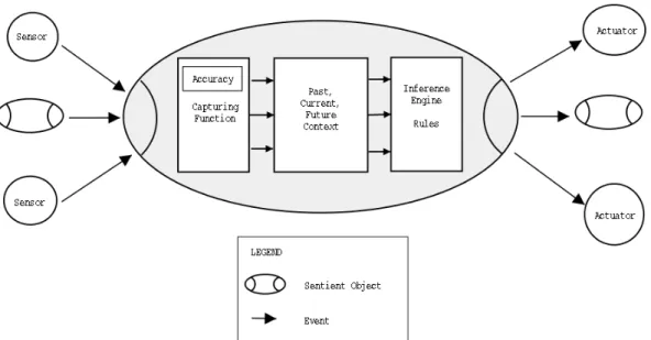
To make sentient objects context aware, three components have been identified which need to be incorporated into sentient objects. A capturing function abstracts raw sensor data into a more useful form, a model of the world is maintained through the representation of past, current and future context, while an inference engine causes the behavior of sentient objects to influenced by their context.
1.3
Event-Based Communication Model
As described in [1], an event-based communication model supporting anonymous one-to-many communication is well suited to provide dynamic pattern of communication arising from the unpredictable manner in which the potentially mobile sentient objects that comprise
an application interact between themselves and the environment. These unpredictable interaction pattern may depend not only on the common interest shared by communicating peers, but also on the geographical proximity of sentient object to one another and the environment.
Chapter 4: presents two technical reports addressing the requirements of event-based programming models. The first report describes the programming model of event-based middleware designed to provide inter-object communication pattern for mobile objects in a wireless environment utilizing an ad-hoc network model. It outlines an approach for event-based communication where objects communicate event-based on events of a certain type, which represent the common interest shared by a group of interacting objects, as well as based on their geographical location. The notion of proximity is introduced to allow an application programmer to define a geographical area within which a particular event type is propagated, thus providing a means to define the scope within which specific events are valid. Furthermore, a novel approach to allow objects to express interest, or lack thereof, in events of a certain type or containing certain parameter values is outlined. This novel approach to filtering of events also supports the ability of a system to easily cope with dynamically joining and leaving objects as well as its ability to grow.
The second report presents a survey of existing event systems structured as a taxonomy of distributed event-based programming systems. It identifies a set of fundamental properties of event-based programming systems and categorizes them according to the event model and event service criteria. The taxonomy serves as a means to identify the properties of event-based middleware in the CORTEX context and is used as basis to discuss the design of the event-based programming model proposed in the first report.
1.4 QoS
Specification
The programming model needs to take into account the provision of incremental real-time and reliability guarantees. To achieve this, the development of a means to express quality of service (QoS) properties in the programming model, where QoS is a metric of predictability in terms of timeliness and reliability, is required. In addition, a global model for QoS assurance across heterogeneous physical networks, must be developed. This dual QoS requirement will be exposed to the programming model via a high-level abstraction of the underlying internetwork, coupled with the novel idea of a hierarchy of zones of guaranteed levels of QoS. An abstract network model, enabling the specification of application level QoS parameters, coupled with a mapping mechanism from these abstract requirements, to system level properties, will be provided to the programming model. Thus, specific QoS guarantees per network, whilst maintaining a complete separation of application developer from the heterogeneity of the physical network, will be achievable.
The basis for the CORTEX architecture is to model the underlying communication infrastructure hierarchically, structured as a WAN-of-CAN. The QoS available for the internetwork varies per network. Individual networks can be viewed as guaranteeing a given QoS degree. For example, strong timeliness guarantees for CANs and weaker guarantees for wireless networks. To take advantage of the varying timing guarantees, each QoS area will be visible as a hierarchy of zones, with each zone capable of delivering specific levels of QoS. A group may be completely contained within a zone, or may span many zones. In the latter case, the QoS must adapt to the weakest QoS guaranteed for the weakest zone. Thus, adaptability, coupled with predictability must be available via this hierarchy of zones approach.
The high-level abstract network model, the mappings from application-level to system properties and the hierarchy of zones for QoS containment will be further discussed in Chapter 5: of this document.
Chapter 2: Sentient Object Model
This chapter is divided into to two major sections. Section 2.1 presents a technical report introducing a description of the properties and operations of sentient objects and section 2.2 presents a paper on smart sensors describing a potential example of a sentient object that has been presented at the IEEE International Conference on Mechatronics and Machine Vision in Practice [6], which took place in August 2001.
2.1 Sentient
Objects
The CORTEX annex [COR01] describes sentient objects as intelligent, mobile, context-aware software components. It envisages applications composed of a great many of these objects, acting autonomously to achieve the application goals. Where necessary, objects will interact to ensure successful completion of goals or to improve system performance. However, the annex fails to supply anything more than high-level notions of what is meant by a sentient object. Consequently, it was felt that the first goal of the project should be to try and more precisely define both the properties and operation of sentient objects.
2.1.1 Initial
Ideas
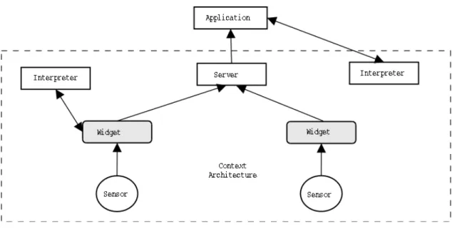
Examination of the sample CORTEX application scenarios [COR02] was the main source of inspiration for initial ideas on sentient objects. Figure (1) below shows a possible sentient object model suggested by these scenarios.
Figure (1): Early sentient object model
The sentient object is an encapsulated entity, with its interfaces being sensors and actuators. The actuators are controlled according to sensor input, via a rule-based system. For example, considering the ATTS scenarios as defined in [COR02], a light sensor might be connected to a headlight actuator via a rule that states that the headlight should be turned on if it is dark. However, one can envisage the rule structure becoming extremely complex in larger sentient objects, where data from multiple sensors must be considered simultaneously, and decisions may require complex behaviour from multiple actuators. In addition, this model is obviously very loosely specified, and does not answer many questions about sentient objects. Some of the major issues that we identified were:
• What is the granularity of a sentient object?
• What do we mean by sensors and actuators in this context – are they hardware devices, or software abstractions thereof?
• How do sentient objects interact?
In addition to answering the questions above, one of the main challenges to be overcome in defining a sentient object was to constrain our definition. The most obvious definition of a sentient object was as something that senses and actuates. However, this is hugely broad classification, which can easily encompass a great many existing computer systems. For example, a desktop computer could be said to sense user input via the mouse or keyboard and actuate on its environment by moving a cursor or displaying a character on the monitor. A more precise definition was needed, which would allow us to state more categorically whether or not a given entity was a sentient object.
2.1.2 Classification
In CORTEX, we identify two distinct categories of events: software events and real-world events. Software events are the main form of interaction between entities in CORTEX and provide anonymous, ad-hoc communication. Real-world events are anything that happens in the environment, either causing a change of state in a sensor or caused by an actuator. We propose that, using these two categories, we can identity and distinguish the different entities that may exist in CORTEX. This is to be done by categorizing any encapsulated entity in terms of the classes of event it can consume, and the classes it can produce. Figure (2) below depicts an entity that both consumes and produces all categories of event. Another entity might only be able to produce and consume software events, for example. The different possibilities for production and consumption lead to the different classifications.
Figure (2): The production and consumption of events
Our initial investigation of the different possibilities for production and consumption considered that an entity could produce only one category of event and consume only one category of event. The resulting classification yields four distinct entity types, which we categorized as follows:
o This class of object produces software events in response to real world events. This seems to suggest that these entities are sensors.
• Software consumption, software production
o This class of entity both consumes and produces software events. One can envisage that application logic will be distributed across entities of this class. This implies that these are sentient objects.
• Software consumption, real world production
o These entities produce real world events in response to the consumption of software events. They have the opposite consumption/production properties to the entities that we have identified as sensors, and hence would appear to be actuators.
• Real-world consumption, real-world production
o This class of entity produces real-world events in response to real-world events consumed. This implies that it is a simply real-world system; in the context of CORTEX, we propose to term such entities sentient systems. From these classifications, we are able to form initial definitions for the entities in CORTEX:
“A sensor is an entity that produces software events in reaction to a stimulus detected by some real-world hardware device”
“An actuator is an entity which consumes software events, and reacts by attempting to change the state of the real world in some way via some hardware device.”
“A sentient object is an entity that can both consume and produce software events, and lies in some control path between at least one sensor and one actuator.”
Our original definition of a sentient object was simply an entity that both produced and consumed software events. However, this definition would have included all objects programmed on current event systems. In order to constrain the definition further, the idea of a control path between sensor(s) and actuator(s) was specified. By doing this, we limit the type of entity in which we are interested to those with real-world interactions. One possibility for a further constraint to be imposed may be that sentient objects should be required to respond in a timely manner, but as yet this has not been specified.
2.1.3 System
Operation
The classifications are useful in that they distinguish between hardware entities, software objects, and the intermediate devices. The idea of a sentient system maps quite well to the notions in [COR01] and [COR02], where, within the various application scenarios, cars, airplanes, etc are identified as the mobile, sentient objects. In our view, these entities would be considered to be sentient systems, and their on-board devices that allow both observation of and interaction with the environment would be sensors and actuators, respectively. Internal objects that consume software events and produce corresponding software events where appropriate would be components of the application logic, known as sentient objects. A depiction of a sentient object is shown in figure (3) below.
Figure (3): A sentient object
The application logic could be separated across as few or as many of these objects as the application programmer deems necessary. This will hopefully give the benefits of object-oriented programming, i.e. re-usability of code modules, separation of logic, etc. Also, we hope this will allow sentient objects to be composed of other, smaller sentient objects in a hierarchal manner. Whether other properties of object oriented software, such as polymorphism and inheritance, can be applied to sentient objects remains to be investigated.
Figure (4): Envisaged operation of a CORTEX application
Figure (4) above shows the envisaged operation of a CORTEX-type system. The boundaries of this entity would most likely be equivalent to the boundaries of a CAN (Controller Area Network) as in the WAN-of-CAN architecture [COR01]. So, the entire system depicted above might represent a car in the ATTS scenario or an aircraft in the ATC scenario [COR02]. While this may provide a useful abstraction to the application programmer, situations can be envisaged where sentient systems, or even sentient objects, may span multiple hardware devices across the WAN1. For the sake of simplicity, we may later specify that this is not
allowed, or perhaps give entities spanning multiple hardware devices different names. However, according to the current definitions, entities existing across multiple hardware devices are permissible.
2.1.4 Classification
II
In the classifications above, we only consider entities that can produce one category of event and can consume one category of event. However, we must also consider the case where an
1 The latter case is only likely to be possible with complex sentient objects, which are composed from more primitive objects.
entity is capable of producing and/or consuming events in more than one domain. For example, consider the case illustrated in figure (5) below:
Figure (5): Example of consumption from two domains
The scene depicted is a possible security system for a bank vault. The frame of Door A is fitted with an embedded sensor system (e.g. infra-red) that detects people passing through the door. This sensor is connected, via a CORTEX sensor wrapper object, to a network. The detection of an individual entering the lobby (real-world event) causes a software event to be published on the network. The CORTEX application, which is running on the control computer, is subscribed to this type of event. When such an event is delivered, the application retrieves an image from the security camera, which is connected to the computer via a USB cable, and is communicating with the application in a non-CORTEX domain. If the person is recognized, an event is issued to cause Door B to open, admitting them to the vault. The non-CORTEX communication is crucial, as this means that the application running on the control computer is itself providing the CORTEX sensor wrapper for the camera. Hence, it is receiving both software events from Door A’s embedded systems, and real-world events from the camera. This dual consumption is not well described by the classifications above.
The possibility of new scenarios such as that described above increases the potential number of entity classifications to nine. We look at each of new classifications in turn, and consider their usefulness and feasibility. Firstly, we look at two new entity classifications that appear to be an enhancement on our original definitions for sensors and actuators, as they allow for such scenarios.
• Real-world and software consumption, software production
o The scenario above describes an entity of this class. It can be viewed as a sensor that also accepts software events as input.
o This entity classification can be seen an actuator that also generates software events as output.
The three remaining entity classifications seem to be of less value, as no scenarios have been conceived in which they are useful or necessary. They all deal with entities that can both produce and consume real-world events. In this respect, they can all be seen as enhancements to the definition of a sentient system, allowing for software consumption and production as well. For clarity, we present the three remaining classifications below.
• Real-world and software consumption, real-world and software production • Real-world and software consumption, real-world production
• Real-world consumption, real-world and software production
In light of these previously unconsidered entity classifications, we must necessarily reconsider our definitions for sensors, actuators and sentient object. In classifying these new entity types, we suggest that real-world events are in some way “more defining” than software events. By this, we mean that the consumption and/or production of real-world events are more crucial to the classification of an entity in CORTEX than the consumption/production of software events. This means that if an entity can consume real-world events, then it will be classified as a sensor, regardless of whether or not it can consume software events. Similarly, if an entity can produce real-world events, then it will be considered to be an actuator. Entities that neither produce nor consume real-world events are sentient objects2. From this, we have our new, revised, definitions of the entities in CORTEX:
“A sentient object is a entity that both consumes and produces software events, and lies in some control path between at least one sensor and one actuator.” (Unchanged) “A sensor is a entity that produces software events in reaction to a stimulus detected by some
real-world hardware device(s). A sensor may also (optionally) receive software events as input.”
“A actuator is an entity which consumes software events and responds by attempting to change the state of the real world via some hardware device(s). An actuator may also
(optionally) produce software events as output”
2.1.5
Related Ideas and Technologies
An area of interest in the initial investigation into sentient objects was the distinction between what we were trying to achieve with sentient objects, and the work of the artificial intelligence community in the field of agents. A review of agent literature revealed a large number of different definitions of what an agent was. Some of these were particularly interesting from a CORTEX viewpoint. The two most relevant definitions are quoted below.
2 These assertions assume the all entities are capable of consuming at least one category of event, and are capable of producing at least one category of event. In addition, they do not apply to entities that both consume and produce real-world events – those entities that we have previously termed ‘sentient systems’.
The AIMA agent [Russell and Norvig 1995]: “An agent is anything which can be viewed as
perceiving its environment through sensors and acting upon that environment through effectors”
The Brustoloni Agent [Brustoloni 1991]: “Autonomous agents are systems capable of
autonomous, purposeful action in the real world. Agents must be reactive; that is, be able to respond to external, asynchronous stimuli in a timely fashion.”
While the definitions presented above appear in many ways to be quite similar to the descriptions of sentient objects found in the CORTEX annex [COR01], they represent only a philosophy of artificial intelligence programming, as opposed to the more rigid application development framework that CORTEX hopes to present. However, further examination of agent-based programming may well become useful at a later stage in the project, when we more fully consider how sentient objects will be programmed.
Another topic that may become more useful as we progress with our investigation into sentient objects is that of visual programming. From what we have already defined about sentient objects, and from what we hope to accomplish, a system for creating applications composed of these objects can be envisaged which uses a graphical user interface rather than more traditional coding methods. A visual model is particularly suited to the application domain in which we are interested, and it is hoped that this will allow the programmer to create applications in a quicker and more intuitive fashion. Altaira [PFE01] is a simple example of the use of a visual programming system in the development of context-aware applications. It is a visual language for the control of mobile robots. It uses icons to represent sensors and actuators, and employs a rule-based logic to specify the behavior of the robot. The context toolkit [DEY01] is an additional existing technology that may be of use to use in defining how we create and program sentient objects. It draws on the ideas of graphical toolkits and widget libraries in order to provide the application programmer with reusable building blocks for applications that use environment/context awareness. In the CORTEX programming model, we wish to make context information available to the application with minimal additional work for the programmer. It is hoped the work and ideas of the context toolkit can be expanded upon to provide context information to sentient objects in a simple, re-useable manner.
2.1.6 Future
Work
Obviously, we are still far from having a complete definition of what a sentient object is, and of how sentient objects will be programmed. We must next consider issues of hierarchy and composition for sentient objects, and examine in more detail the relationships between the entities that we have identified so far – how these entities will come together to form larger systems, how larger entities can be composed from more primitive ones, etc. In addition, we will consider the interactions that will take place between different entities, via the real world and also via the event-based communication service, which we must also specify in more detail. The main challenge in this is to select an event model that is capable of providing suitable abstractions of the facilities that the lower levels of the CORTEX model aims to provide, such as group communication and quantifiable QoS, and is also capable of the anonymous, ad-hoc communication that CORTEX applications will require. Finally, we must examine issues of context – how the different entities in CORTEX will perceive and interact with the environment and how they with represent their surroundings internally. We hope to provide mechanisms that will simplify the use of context at an application level, shielding the programmer from the complexities of obtaining and manipulating contextual information. These mechanisms will probably be similar to those seen in the context toolkit. From here, we hope to be able to more clearly specify the programming model for CORTEX.
2.1.7 References
[COR01] CORTEX – “Annex 1, Description of Work”, October 2000. [COR02] CORTEX – “Definition of Application Scenarios”, October 2001.
[HAA01] M. Haahr, R Meier, P. Nixon, V. Cahill, E. Jul – “Filtering and Scalability in the ECO Distributed Event Model”, April 2000.
[DEY01] A. Dey, G. Abowd – “Towards a better understanding of Context and
Context-Awareness”, September 1999
[PFE01] J. Pfeiffer – “A Rule-Based Visual Language for Small Mobile Robots”, September 1997
2.2
ICU - A Smart Optical Sensor for Direct Robot Control
Jörg Kaiser and Peter SchaefferDepartment of Computer Structures, University of Ulm, Germany e-mail: [email protected], [email protected]
Abstract-- Technological advances will allow the integration of smart devices which may comprise sensor components, computational devices and a network interface. The built-in computational component enables the implementation of a well-defined high level interface that does not just provide raw transducer data, but a pre-processed, application-related set of process variables. The paper deals with two issues. Firstly, it describes an architecture which encourages the design of multi-level control hierarchies exploiting the easy availability of application related sensor information. This is based on encapsulated smart components, a well defined communication interface and the easy access to this information by a variant of a shared data space. Secondly, we describe the functions and the hardware of ICU which constitutes the prototype of an optical sensor designed for vehicle guidance operating as a smart component in such a system. The task of the sensor is to detect a guidance line and directly produce the information needed by the steering system to control the vehicle.
Index terms-- Vehicle guidance, co-operative control, low cost sensor, smart sensor, middleware, CAN-Bus interface
2.2.1 Introduction
Technological advances will allow the integration of smart devices which may comprise sensor components, computational devices and a network interface. The built-in computational component enables the implementation of a well-defined high level interface that does not just provide raw transducer data, but a pre-processed, application-related set of process variables. Consequently, the interfaces and the functions of these smart components may include functions related to overall control, supervision, and maintenance issues. In his excellent survey of vision sensors, Alireza Moini [1] makes the point that “smart sensors are information sensors, not transducers and signal processing elements”. Perhaps the most interesting and challenging property of these intelligent devices is their ability to spontaneously interact with the overall system. This enables a modular system architecture in which smart autonomous components co-operate to control physical processes reactively without the need of a central co-ordination facility. In such a system, multiple different sensors will co-operate to augment perception of the environment and autonomous actuators will co-ordinate actions to increase speed, power and quality of actuation thus forming decentralized virtual sensor and actuator networks.
As an example consider the vision tasks of an autonomous mobile robot. There may be multiple levels of image processing and recognition ranging from line tracking over obstacle avoidance to scene recognition and image understanding [2]. All these tasks need different levels of reactivity. With multiple dedicated low cost/low power sensors, the need for a fast reactive behaviour can be met without interfering with higher levels. The output of the tracking sensor can directly be used by the motor drive system to keep the vehicle on a guidance line, the obstacle detection sensor may directly stop the motors with minimal
latency. Higher level analysis may use the same sources of data but usually is less predictable and responsive because it will have to relate multiple sensors in more complex planning and recognition tasks.
In the context of a project dealing with adequate models and middleware techniques for communication and co-ordination in control systems [3], we developed ICU (Intelligent Camera Unit). ICU is an optical sensor which computes and disseminates information which is directly related to actuator control rather than deliver just the raw image for further processing.
The rest of the paper is organized as follows. Section 2 motivates a distributed control architecture composed from smart components. In 3, we describe the requirements and intentions of such an architecture and briefly sketch the main ideas. The functions and basics of ICU are covered in 4 while section 5 details the hardware architecture. Conclusions and acknowledgements are given in 6 and 7, respectively.
2.2.2
Co-operating Optical Sensors
There is a large variety of optical sensors and vision sensors ranging from very simple CCD and CMOS arrays to intelligent vision chips and artificial retinas [1]. They can detect relatively simple things as distributions of light intensities or detection of marks or lines. More sophisticated sensors enable motion detection and deriving the speed of a device from optical flow analysis directly embedded in the sensor array [4]. These devices are usually specialized to a single function which they can perform faster, better and with less energy as compared to traditional vision systems which usually convert a digital image in a an analogue format coming from the first days of television and then use a frame grabber easily wasting 30 Mbyte of PCI bandwidth again to create a digital image in the processor memory. The advantage of this approach is its generality, i.e. that an image, once in memory is the raw material which can be analysed by software in any desired aspect. However, high performance processors are needed resulting in an overall complex and rather power consuming system. For autonomous mobile vehicles this may be a problem. On the other hand, specialized optical devices only perform a single task. Therefore, multiple such devices may be needed to collaboratively sense and improve the perception of the environment. Special purpose sensors can operate in different spectral ranges and can be used to built robust systems with the possibility to use adaptive strategies to replace defective functions by “virtual sensors” combining the virtues of active sensors, probably with lower precision, timeliness or resolution. To combine these sensors in an effective and robust way and enable direct actuator control, distributed middleware is needed to support easy diffusion of the information to each entity which may be interested in the data, to support spontaneous generation of information and allow temporal constraints to be specified on information propagation. Moreover, it is desirable to have a low configuration effort when integrating new sensors.
2.2.3
Requirements for the System Control Architecture
Traditional control systems usually center around a single control unit (CU) which has a sophisticated real world interface. The CU is the last link in a chain of transducers, converting a physical process variable, like a temperature, a pressure or an optical signal via a electrical signal to a digital representation. Signal conditioning as shaping analogue values, debouncing digital inputs and improving an image received from a camera all are performed by this CU. The resulting digital information is a raw, conditioned representation of a single physical entity. Subsequent processing, fusion of multiple sensors information, and generation of control signals for the actuators also is performed by the same processor. Because all these tasks have widely differing performance requirements and temporal constraints, complex planning and scheduling schemes have to guarantee that these tasks can be properly
coordinated in the temporal domain. Simply moving to multiprocessors usually worsens the scheduling problem [5].
Using decentralized smart sensors and actuators puts computing power to the place where it is needed. These components are autonomous systems which perform a dedicated complex task beyond signal conditioning. Interconnected by a communication network, they encapsulate a certain functionality and provide meaningful application related information at their network interface. Kopetz [6] highlights the importance of an adequate interface to support functional and temporal encapsulation of smart components to support the composability of an application.
There are a number of goals which we want to reach for the control system architecture: 1. Components of the network are autonomous. Autonomy means that each component is in
its own sphere of control and no control signal should cross the boundary of a component. Hence, components only interact via shared information as e.g. proposed in the data field architecture in ADS (Autonomous Decentralized Systems)[7] or the tuple space in Linda [8]. As a consequence, interfaces can be created which do not rely on any, possibly time critical control transfers. This supports easy extensibility, reliability and robustness and encourages a component-based design.
2. The architecture should support many-to-many communication patterns. A typical situation is that the information gained from a sensor can be used and analyzed in more than one place, e.g., the output of a our ICU optical sensor on a mobile robot is interesting for reactive motor control implemented on a small micro-controller as well as for long term navigation strategies implemented on a more powerful device. Another typical example is the situation in which control commands issued from a controller address a number of identical actuators; e.g., all motors have to stop in case of emergency.
3. Communication is spontaneous because control systems have to react to external events. These external events are recognized at the sensor interface of an embedded system at arbitrary points in time and lead to communication activities to disseminate the information. This is best captured in a generative, event-based communication model [9, 10, 11].
4. Communication is anonymous. Consider again the example of stopping a set of motors. When issuing a stop command, it is not of interest to address a specific motor, rather it must be ensured that all relevant motors receive the command. Similarly, when reacting to a stop command, it is not of interest which controller has issued that command. On a more abstract level, a sensor object triggered by the progression of time or the occurrence of an event spontaneously generates the respective information and distributes it to the system. Thus, it is considered as a producer. The corresponding consumer objects have mechanisms to determine whether this information is useful for them. This interaction leads to a model of anonymous communication in which the producer does not know which consumers will use its information and, vice versa, the consumers only know which information they need independently from which source they receive it. Furthermore, anonymous communication supports the extensibility and the reliability of the system because objects can be added or be replaced easily without changing address information maintained in the other objects.
To meet these requirements, we adopted a publisher/subscriber model of communication in which producers (publishers) and consumers (subscribers) of data are connected via event channels [7, 8]. In contrast to other forms of a shared information space [9, 10], the semantic of event channels integrates the notification of consumers when an event occurs and thus support the temporal relation of the event occurrence and the notification of the subscribers. Event channels support content-based communication by relating an event channel to a certain class of information rather than to a source or destination of a message. Thus, a message is routed by its content which is dynamically bound to a network related address. A
more detailed description of this architecture can be found in [3]. What mainly distinguishes our publisher/subscriber scheme from existing schemes like the event service in Jini[11] is its anonymity and compared to the event service in CORBA[13] the distributed implementation. In our system, an event channel is related to a certain class of information, like e.g. certain classes of tracking information. Publishers may be smart cameras, infrared sensors and alike all pushing tracking information in the respective event channels. Multiple subscribers e.g. motor control or the navigation system receive this information and can locally filter and use it. The publisher/subscriber architecture was particularly designed to enable interoperation of embedded systems which usually have stringent performance and bandwidth constraints with more powerful networks and processors. At the moment we provide interoperability between a CAN-Bus [14] for low level reactive control and IP-based protocols. This allows a robot in a co-operating team to seamlessly access remote sensor information of another robot e.g. via a wireless IP connection.
Autonomous components encourage the design of layered intelligent systems as they were proposed by [2], [15], [16]. Most authors separate the reactive layer from higher system levels which realize deliberative behavior. Reactive behavior maps to the low level control architecture in which resources have to be provided to support fast and timely behavior with respect to safety critical actions like avoiding obstacles, recognizing landmarks or coordinating actions of multiple actuator devices. Deliberative behaviors include to a large extend activities related to planning like map building, path planning, global navigation and action co-ordination. Reactive and deliberative behaviors may be based on the same set of sensor information, however with a different degree of relating sensor information and different temporal attributes. This even may include co-ordination of different robots each equipped with a set of different sensors co-operating to jointly explore an unknown environment.
A prototype of our publisher/subscriber architecture is implemented under Linux and RT-Linux. Linux handles the non-critical communication over IP while RT-Linux is used for the time critical communication on the CAN-Bus. A gateway connects the two networks [17]. The testbed is a KURT II autonomous robot which besides various distance and odometric sensors is equipped with ICU (Fig.1).
Fig.1 Kurt-2 robots, robot in front carries ICU (courtesy of Michael Mock, Institute of Autonomous intelligent Systems (AiS))
2.2.4
Functions of the ICU
ICU was primarily designed for vehicle guidance in an experimental traffic scenario. In our first application ICU tracks a guidance line (G-line) on the floor which may include embedded coloured marks. ICU disseminates the position and orientation of the G-line and the colour of the embedded marks. The information delivered by ICU is then directly used by the motor drive system to reactively keep the vehicle to follow this line, to slow down or to stop if a certain coloured mark is detected. Fig. 2 shows the principles of detecting a G-line (the white bar in the figure). The orientation of the G-line is calculated from three scan lines (lines). Because of the special colour representation (see Fig. 4) of the image sensor an S-line is represented by 4 pixel-S-lines.
ICU tries to detect the white G-line on a darker background. To do this, the image is transferred to the micro-controller which calculates the colour and brightness values of every pixel on the S-line. The maximal value of brightness is then used to detect the G-line. Therefore, the G-line must be a white line with optionally embedded coloured marks (see Fig. 2 and 3).
Upper scan line
Center scan line
Lower scan line
Perception window
Fig.2 Principle of line detection
The problem encountered in determining the overall brightness is the colour representation. The vision sensor uses a Bayer scheme [18] as depicted in Fig. 4. Hence, the colour of an individual pixel has to be inferred from the relative brightness of the adjacent pixels. Having determined the colour of a pixel, its brightness is calculated using the weighted colour values as described below. The Bayer colour encoding uses 4 pixels to represent the values of red, green and blue.
ICU tries to detect the white G-line on a darker background. To do this, the image is transferred to the micro-controller which calculates the colour and brightness values of every pixel on the S-line. The maximal value of brightness is then used to detect the G-line. Therefore, the G-line must be a white line with optionally embedded coloured marks (see Fig. 2 and 3).
Fig.3 A line as ICU sees it
The problem encountered in determining the overall brightness is the colour representation. R: Red G: Green B: Blue G G R B R: Red G: Green B: Blue G G R B G G R B
Fig. 4 Bayer Scheme of colouring
The vision sensor uses a Bayer scheme [18] as depicted in Fig. 4. Hence, the colour of an individual pixel has to be inferred from the relative brightness of the adjacent pixels. Having determined the colour of a pixel, its brightness is calculated using the weighted colour values as described below. The Bayer colour encoding uses 4 pixels to represent the values of red, green and blue. Therefore, taking the straightforward approach to directly use these values to represent a single coloured pixel would decrease the resolution of the image by a factor of 4 which was not acceptable. Hence, we used a standard colour encoding scheme which exploits the brightness values of a 3x3 neighbourhood as depicted in Fig. 5. Fig. 5 shows how the colour of a (single) pixel is calculated. Even though the spectral sensitivity of a single pixel is confined to a certain colour, an RGB-value will be assigned to it by considering the adjacent pixels. The RGB-value is calculated according to the weights of the adjacent pixels as depicted in Fig. 5. Subsequently, the brightness of every pixel is calculated on the basis of the RGB-values by the equation:
Brightness B =(R*38+G*75+B*15)/128
Thus we maintain the full resolution of the image in spite of the Bayer colour representation, however, the algorithm has the effect of the low pass filter. As a consequence, the image inevitably looses sharpness.
The next step is detecting the G-line. For this, the S-line is scanned from both sides to find the respective transition of contrast. The algorithm is rather straightforward for the moment and only checks whether the edges detected from the left-to-right and right-to-left scan have a certain distance from each other corresponding to the assumed width of the G-line. If not, a fault value is returned. All three S-lines are evaluated as depicted in Fig. 2 to determine the position and orientation of the tracking line.
The last step is to determine the colour of the marks embedded in the G-line. As Fig. 3 shows it calculates the position of the centre of the G-line and takes the colour and the brightness of the pixel at this position. If the G-line is not detected properly, ICU interpolates the respective centre position from the positions of the G-line in the upper and the lower S-line. Subsequently, the colour of the pixel at this interpolated position is selected. This approach is also useful for intersections or junctions of G-lines.
1 G G R B G G R B G G R B G G R B G G R B G G R B 1/4 1/4 1/4 1/4 1/4 1/4 1/4 Blue Red Green Green 1/4 1/8 1/2 1/2 1/8 1/2 1/2 1/8 1/8 1/2 1/8 1/2 1/2 1/8 1/2 1/2 1/8 1/8 1/2 1 1/4 1/4 1/4 1/4 1/4 1/4 1/4 1/4 1 G G R B G G R B G G R B G G R B G G R B G G R B 1/4 1/4 1/4 1/4 1/4 1/4 1/4 Blue Red Green Green 1/4 1/8 1/2 1/2 1/8 1/2 1/2 1/8 1/8 1/2 1/8 1/2 1/2 1/8 1/2 1/2 1/8 1/8 1/2 1 1/4 1/4 1/4 1/4 1/4 1/4 1/4 1/4
Fig. 5 Colour encoding
The sensor is rather sensitive to the precise focus of the lens. Currently, because the sensor always has a fixed distance to the G-line, focussing has only been performed once and therefore is done by hand. Because ICU usually does not provide an image for inspection to adjust the focus, we provided a focussing aid based on an automatic detection of a maximum contrast transition of an appropriate black to white edge. We only use green pixels for the mechanism because colour is not needed and green pixels are dense on the sensor (see Fig. 4 and 5) whereas lines of blue or red pixels always exhibit gaps. The green pixels are arranged in a zick-zack pattern which, however, does not have a major influence on the detection of a black-to-white transistion.
Fig. 5 Scanning for focussing control
If the lens is out of focus, the contrast edge is blurred meaning that the values of adjacent pixel do not exhibit a sharp transition. By adjusting the focus precisely, adjacent pixels indicate a sharp transition which in turn triggers an LED for external inspection. The condition for the LED is a maximal brightness difference that is above a certain threshold between any two adjacent pixels.
2.2.5
The Hardware of ICU
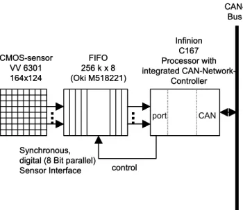
ICU was intended as a low cost sensor for simple imaging tasks which can directly by used for control applications. ICU should be adaptable to various simple vision tasks. Therefore, we took a camera/processor approach and put emphasis on an easy and fairly universal processor interface. Fig. 6 depicts the basic components of ICU. We connect the sensor to an asynchronous external port, which is not the most efficient way but eases the use of different micro-controllers. In fact, we used the front end sensor and the interface logic even with a simple micro-controller as Motorola 68HC11 for educational purposes. In the current version, a 16-Bit controller C167 from Siemens [19] (now provided by Infineon) is used featuring a minimal instruction execution time of 100ns and a peak rate of 10Mips.
CMOS-sensor VV 6301 164x124 FIFO 256 k x 8 (Oki M518221) Infinion C167 Processor with integrated CAN-Network-Controller port CAN control Synchronous,
digital (8 Bit parallel) Sensor Interface CAN-Bus CMOS-sensor VV 6301 164x124 FIFO 256 k x 8 (Oki M518221) Infinion C167 Processor with integrated CAN-Network-Controller port CAN control Synchronous,
digital (8 Bit parallel) Sensor Interface
CAN-Bus
Fig. 6 The main components of ICU
The heart of the interface logic is a FIFO which decouples the fast synchronous operation of the sensor from the slower asynchronously operating processor interface. The only control line from the sensor to synchronize the processor with the sensor is a “start-of-frame” signal. The FIFO can buffer up to 13 frames which are delivered by the sensor with a maximum rate of 30 frames/sec. Currently, we only use 15 frames/sec, partly because of the port interface to the processor which is rather slow in copying data from the FIFO to the processor memory. ICU has a CAN-Bus [14] network interface which is popular in automotive and industrial control systems and allows transfer rates up to 1 Mbit/sec with a protocol efficiency of about 50% payload. The maximal length of a single CAN-Bus message is 8 Bytes. The CAN-Bus was designed to reliably operate in environments exhibiting high electric noise, but obviously not for high speed data transfer. Therefore it would be impossible to transfer raw image data which would need around 2,3 Mbit/sec (160*120 pixels, 1 byte/pixel, 15 frames) even for the low resolution sensor. However, the pre-processed complete information to control the movement of the vehicle fits into a single CAN message and puts no significant load on the communication system.
At the moment ICU can be configured to either periodically publishing position and colour information on the CAN-Bus or to transmit a tracking position on demand. A small local software component, called event channel handler connects ICU to the publisher/subscriber middleware. The information delivered in a CAN message by ICU is depicted in Tab.1. ICU disseminates:
1. the position of the G-line within its window of perception, 2. the colour in separate values for red, green and blue and 3. brightness information
š_Ÿ8.›‡ š_‡C‚ƒ‡`—ƒ._—VrV™ z9 ~ŒiÐ=“@n›qÕ._qL“@r_y.qLrVqu‡†“5ž>‡`r ¡9 ~ŒiÐ=“@n›qÕ._qL“@r_y.qLrVqu‡†o_qÕ.›.›‡ Ñ9 ~ŒiÐ=“@n›qÕ._qL“@r_y.qLrVqu‡†—Vr8.›‡|r cO“/._l5r8.›‡`qu”.tbqL.‘._‡`”u£V—VrV¬8. ´Úm… ’ —Vrsl5r8.›‡`qu”.tbqL.‘._‡`”u£V—VrV¬8. {š_”-l/—sl5r8.›‡`qu”°tbqL.‘._‡`”uLV—VrV¬8. }7 d‡`”u”Lqu™5¬@‡`qL.dtbqL.‘.›‡|”L£s—VrV¬8. Ik_‡`…_‹`‡|qÕ.0—sr8ž>‡`”u‡`™5.
Byte Content
1 x-position on upper line 2 x-position at center line 3 x-position at lower line 4 R-intensity 5 G-intensity
6 B-intensity 7 Brightness
8 Not used
Tab. 1 Payload of the CAN message
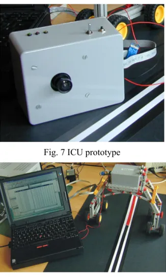
ICU is configured via the CAN-Bus. The configuration message defines the rate of the tracking information. If the configuration message is empty, i.e. it does not include any parameters, the camera returns a single message. In addition to the CAN interface, a serial interface is available for debugging purposes and for changing the flash memory of the micro-controller. Fig. 7 and Fig. 8 show the ICU prototype and the test environment depicting ICU hooked to a CAN analysis tool.
2.2.6
Conclusion and Future Work
Design of control systems for complex artifacts like autonomous vehicles, driver assisting cars, airplanes and industrial plants tend to become enormously complicated. One step towards solving the problem is to provide computational power at the sensors and actuators making them smart devices encapsulating all computations needed to convert a physical process value to an application related meaningful information. The autonomy and encapsulation properties encourage hardware/software co-design on the device level and component-based design methodologies [20] for putting the building blocks together. In the context of a project dealing with appropriate models and mechanisms to support decentralized systems composed from these components, we developed a couple of smart sensors.
Fig. 8 Test environment for ICU
ICU is an optical sensor specialized on recognizing a tracking line for vehicle guidance. ICU provides tracking information via a CAN-Bus interface and the respective middleware, thus making it available to any entity which may exploit this information. This may be the smart motor controllers for directly steering the vehicle or a navigation system just logging the course. ICU is the first prototype of a low cost/low power optical sensor which is used in such an environment. Because ICU is adapted to a single application related function, resources like hardware, communication bandwidth and power consumption can be reduced to a minimum just as required by the application. ICU is designed for vehicle guidance based on tracking predefined lines and marks. At the moment, we use off-the-shelf processor boards [21] and only designed the glue hardware ourselves. In the future, we will be working in two directions: 1. we will design better and more robust algorithms to detect G-lines particularly detecting intersections and junctions of G-lines. 2. we will design a processor board which provides a faster interface to the optical sensor to enable more sophisticated vision tasks without substantially increasing power consumption which at the moment is around
250mA@5V for the entire ICU.
2.2.7 Acknowledgements
The work on ICU was partly sponsored by GMD AiS3 and the University of Magdeburg. We
want to thank Michael Mock (GMD) Edgar Nett (U. Magdeburg), Reiner Frings (GMD) and Martin Gergeleit (U. Magdeburg) for their co-operation and support. Particularly, we want to acknowledge Michael Wallner’s effort to integrate ICU in the publisher/subscriber communication environment. This work was partly funded by the EU in the CORTEX4
Project under the contract No.: IST-2000-26031.
2.2.8 References
[1] Alireza Moini: Vision Chips or Seeing Silicon, Third Revision,
http://www.eleceng.adelaide.edu.au/Groups/GAAS/Bugeye/visionchips/index.html,
March 1997
[2] R.A. Brooks: A robust layered control system for a mobile robot, IEEE Journal of
Robotics and Automation, vol. RA-2, no.1, March 1986
[3] J. Kaiser, M. Mock : Implementing the Real-Time Publisher/Subscriber Model on the Controller Area Network (CAN), Proceedings of the 2nd Int. Symp. on
Object-oriented Real-time distributed Computing (ISORC99), Saint-Malo, France, May
1999
[4] J. Tanner, C. Mead: An integrated analog optical motion sensor, in R.W. Brodersen
& H.S. Moscovitz, editor, VLSI Signal Processing, II, pp. 59{87. IEEE, New York,
1988.
[5] J. Stankovic: Misconceptions about Real-Time Computing, IEEE Computer, 1988 [6] H. Kopetz, E. Fuchs, D. Millinger, R. Nossal: An Interface as a Design Object,
Proc. Int’l Symp. on Object-oriented Real-Time Distributed Computing (ISORC-99),
St. Malo, France 1999
[7] B. Oki, M. Pfluegl, A. Seigel, D. Skeen: "The information Bus®- An Architecture for Extensible Distributed Systems", 14th ACM Symposium on Operating System
Principles, Asheville, NC, Dec 1993,pp.58-68
[8] R. Rajkumar, M. Gagliardi, L Sha: " The Real-Time Publisher/Subscribe Inter-Process Communication Model for Distributed Real-Time Systems: Design and
3GMD AiS: German National Research Institute for Information Technology, Institute for Autonomous Intelligent Systems 4 CORTEX: CO-operating Real-time senTient objects: Architecture and Experimental evaluation.
Implementation", IEEE Real-time Technology and Applications Symposium, June 1995
[9] K. Mori. Autonomous decentralized Systems: Concepts, Data Field Architectures, and Future Trends, Int. Conference on Autonomous Decentralized Systems
(ISADS93), 1993
[10] N. Carriero, D. Gelernter: "Linda in Context", Communications of the ACM, 32, 4, April 1989
[11] Rene Meier: State of the Art Review of Distributed Event Models, Tech. Report
TCD-CS-2000-16, Trinity College, Dublin Ireland, March 2000
[12] T. Harrison, D. Levine, and D. Schmidt: The design and performance of a real-time CORBA event service. In Proceedings of the 1997 Conference on Object-Oriented Programming Systems, Languages and Applications (OOPSLA), 1997
[13] Sun Microsystems. Java Distributed Event Specification. Sun Microsystems, Inc., July 1998, http://www.javasoft.com/products/javaspaces/specs
[14] Object Management Group. CORBAservices: Common Object Services
Specification - chapter 4, Event Service Specification. Object Management Group, March 1995. http://www.omg.org/library/csindx.html.
[15] ROBERT BOSCH GmbH: "CAN Specification Version 2.0", Sep. 1991
[16] D. J. Musliner: CIRCA: The Cooperative Intelligent Real-Time Control
Architecture, PhD-Dissertation, University of Michigan, 1993
[17] K. Z. Haigh: Situation-Dependent Learning for Interleaved Planning and Robot Execution, Tech. Report CMU-CS-98-108, CMU, February 1998
[18] M. Wallner: Ein Publisher/Subscriber-Protokoll für heterogene Kommunikationssysteme, Master thesis, University of Ulm, March 2001
[19] VLSI Vision Ltd: VV6300 Low Resolution Digital CMOS Image Sensor, Technical Description cd 34021-b.fm, UK, 1998, www.vvl.co.uk
[20] Siemens AG: 16 Bit Micro-controllers – C167 Derivatives, User Manual 03.96 Version 2.9, 1996
[21] C. E. Pereira , L. B. Becker, C. Villela, C. Mitidieri , J. Kaiser : On Evaluating Interaction and Communication Schemes for Automation Applications based on Real-Time Distributed Objects, Proceedings of the 2nd Int. Symp. on
Object-oriented Real-time distributed Computing (ISORC2001), Magdeburg, Germany, May 2001
[22] Phytec: Mini-Modul 167 Hardware Manual, Phytec Messtechnik GmbH, Mainz, 1999, http://www.phytec.de
Chapter 3: Context Awareness
This chapter presents a position paper on “Context Awareness in CORTEX”.
3.1 Introduction
CORTEX defines sentient objects, mobile intelligent software components that accept input from a variety of sensors allowing them to sense their environment before deciding how to react, by way of actuators. It is this awareness of, and interaction with the environment, which makes context awareness an important factor in sentient objects.
This paper examines the meaning of context and context awareness in terms of CORTEX and proposes a model for the development of context aware sentient objects. Our model draws on ideas from the domain of Context Based Reasoning.
3.2
Definition of Context
Before examining the role of context in CORTEX, a clear definition of what we understand by context is required. There are multiple definitions of context available in the literature. Schilit et al. [1] name the three important aspects of context as being where you are, whom you are with and what resources are nearby. They go further to divide context into the categories of Computing context, User context, and Physical context.
Dey et al. [2] provide a definition of context which aims to ease the enumeration of context for a given application scenario. Their definition of context follows “Context is any information that can be used to characterize the situation of an entity. An entity is a person, place or object that is considered relevant to the interaction between a user and an application, including the user and applications themselves.” This definition of context is less specific than others, for example [1], in that it does not prescribe what aspects of context are important, rather leaving this to be done on an individual basis for each situation. For example user context may not be relevant to an autonomous sentient object, whereas the Quality of Service (QoS), or infrastructural context, provided by the underlying architecture is of more importance to the sentient object. In [2], 4 types of context are identified as being, in practice, more useful than others, these being location, identity, activity and time.
Chen et al. [3], define two aspects of context in mobile computing these being the characteristics of the surrounding environment that determine the behavior of an application and those that are relevant to the application, but not critical. These differences are taken into account in their definition of context, which follows “Context is the set of environmental states and settings that either determines an application’s behavior or in which an application event occurs and is interesting to the user.”
For the purposes of CORTEX we propose a definition of context as:
Any information sensed from the environment, which may be used to describe the current situation of a sentient object. This includes information about the underlying computational
infrastructure available to the sentient object.
3.3
Definition of Context-Aware
A context-aware application is an application whose behavior is controlled by its context, to some degree.
Dey et al. [2] define a system as being context-aware if it “uses context to provide relevant information and/or services to the user, where relevancy depends on the users task”. Their definition is influenced by the observation that a context aware system does not necessarily have to adapt to its context, it may just sense and display, or stores its context.

![Table 1: Categories of context aware applications [1]](https://thumb-eu.123doks.com/thumbv2/123dok_br/15453306.1028214/30.892.151.742.392.503/table-categories-of-context-aware-applications.webp)