Computational Block Templates Using Functional Programming Models
Paulo Ferreira
†, Jo˜ao Canas Ferreira
‡, Jos´e Carlos Alves
‡†
Instituto Superior de Engenharia do Porto,
‡Universidade do Porto,Faculdade de Engenharia
[email protected], [email protected], [email protected]
Abstract
The elaboration of computational blocks using declara-tive models, typical of functional languages, allows the use of a parameterized template for the hardware design. This paper shows how such a template can be created, for the hardware implementation of computational blocks based on a declarative model, and how it can be used to provide design space exploration alternatives and hardware accel-eration for Erlang based embedded systems. The template uses a flexible TCL preprocessor for the HDL generation and control of the design space alternatives.
1. Introduction
The use of custom hardware to implement functional or declarative languages has been studied by many. This re-search was usually oriented to the complete implementa-tion of funcimplementa-tional languages in hardware, like the elabora-tion of a LISP based microprocessor [1] or the the creaelabora-tion of machines such as SKIM [2] and the parallel execution of functional programs [3]. This area of research is a conse-quence of study of High Level Computer Architectures in the 1970-1980 decades [4].
Different functional languages have been applied to hardware description tasks, such as Lava [5], Shard [6] or BlueSpec [7], but the majority of work that tries to apply high-level languages to hardware description uses impera-tive (and object-oriented) languages or derivaimpera-tives such as C, C++, and Java.
The “absence of state” in functional languages [8], is usually a shock for programmers fluent only in imperative programming languages. However, in parallel architectures the existence of state, means that the state must be shared among different execution threads (or similar abstractions), originating many difficult problems [9].
A very different parallel computing model is used on the Erlang functional language [10] where a system is built from independent processes, not sharing any state and com-municating only by message passing. This has a strong re-semblance to hardware design, where one can build a sys-tem from different hardware blocks, without a global phys-ical memory, using point to point connections, crossbars or networks-on-chip for communication.
The heterogeneous architecture of an Erlang system based has two interesting characteristics:
• It has a strong similarity to hardware.
• It has no strong coupling between the different pro-cesses.
This might mean that a Erlang based system, could be mapped entirely into heterogeneous hardware computa-tional blocks. That would be very interesting. However, a more achievable task is the mapping into hardware of only some of those processes, selected considering the require-ments of the full system.
As the coupling between the different processes is done by the messages, as long as the same messages arrive in the same format, with the same data, and a “process” does the same work, the “process” can be “migrated” from software to hardware without changes on the rest of the system.
In this paper some different implementation alternatives for those computational blocks, are presented together with a set of tools that facilitate their creation, use and test. This will allow the design space exploration of FPGA imple-mented coprocessors for Erlang based embedded systems.
2. The general template
The translation into a state machine template of a gen-eral function expressed in a declarative form (usually tail recursive) is described in [11]. In the remainder of this ar-ticle the Erlang language is used for the source code exam-ples. On listing 1 there is a small Erlang code fragment that implements the greatest common divider algorithm, with line numbers added for reference purposes.
1: gcd(A, B) when A<B -> gcd(B, A); 2: gcd(A, 0) -> A;
3: gcd(A, B) -> gcd(A-B, B).
Listing 1 – A sample Erlang greatest common divider (GCD) function
An Erlang function is composed by a series of clauses (lines of code) and each clause has:
• A condition, that may be explicit or implicit.
• An action, that specifies the steps to be executed if the associated condition is true.
The conditions are tested sequentially, and the first one found to be true triggers the execution of the associated action. Translated into common english, the above code fragment can be written as:
1. If the first argument of the function (A) is smaller than the second (B), swap them and call again the same function.
2. If the second argument (B) is zero, then the result of the function is the first argument (A) and the function execution ends here.
3. Call again the function but replacing the first argu-ment (A) with the difference between both arguargu-ments (A-B).
On the first clause, there is an explicit condition (A<B). On the second clause the condition is implicit (B==0), and on the last clause one can assume also the presence of an implicit (true) condition.
As an example the execution of the function call gcd(15,25)can be traced as done in table 1.
Table 1. Tracing the execution of gcd(15,25)
Call Clause Matches Result
gcd(15,25) 1 Yes gcd(25,15)
gcd(25,15) 1 No See next clause
gcd(25,15) 2 No See next clause
gcd(25,15) 3 Yes gcd(25-15,15)
gcd(10,15) 1 Yes gcd(15,10)
gcd(15,10) 1 No See next clause
gcd(15,10) 2 No See next clause
gcd(15,10) 3 Yes gcd(15-10,10)
gcd(5,10) 1 Yes gcd(10,5)
gcd(10,5) 1 No See next clause
gcd(10,5) 2 No See next clause
gcd(10,5) 3 Yes gcd(10-5,5)
gcd(5,5) 1 No See next clause
gcd(5,5) 2 No See next clause
gcd(5,5) 3 Yes gcd(5-5,5)
gcd(0,5) 1 Yes gcd(5,0)
gcd(5,0) 1 No See next clause
gcd(5,0) 2 Yes Result: 5
The corresponding flowchart that triggers each action, when a condition is true, is shown in Figure 1.
Initialization Action 1 Action 2 Action n Condition 1 ... Condition 2 Condition n ... True True True False False
Figure 1. General execution flowchart
The absence of state in a functional language means that a variable does not change it’s value after being assigned. That is the origin of the “single assignment” designation of those languages. So, if a variable does not change it’s value and all the variables used in the conditions are known when a function is called, on figure 1 all the conditions can be tested in parallel (for speed) providing only the action cor-responding the first condition found to be true is executed.
3. The template implementation
3.1. Tools used
For testing the different alternatives of implementa-tion there was the need of generating the required Verilog source code, in an automatic manner. To create automati-cally Verilog (or VHDL) code, when the language’s prepro-cessor and/or the generate statement is not enough, many authors propose (and use) many different alternatives.
One of the common alternatives is to write a custom pro-gram in a compiled language (such as C or C++) to write the required HDL files [12] [13]. Other options involve the use of interpreted languages [14] [15], chosen by their in-teractivity.
The pre-processor used was chosen, taking into account the following requirements:
• The pre-processor should not be Verilog specific • The language used when programming the
pre-processor should also be useful for other common FPGA design tasks
When all the previous requirements were taken into ac-count, the G2 preprocessor [16] was chosen. It is a small open source tool that supports mixing TCL with the de-sired target language. TCL is an Open Source language [17], built in a wide range of EDA tools and is useful for many other tasks, from creating FPGA synthesis projects to controlling digital simulations.
It supports controlling the source code generation with the TCL decision constructs, and the use inside Verilog of TCL variables.
At the time of writing, the computational template au-tomatically generates the desired Verilog code for the the full implementation of the required Verilog modules from a very simple TCL specification, giving alternatives for the parallel or sequential evaluation of the conditions.
As an example the required text for the Erlang GCD example (Listing 1) is shown on listing 2, with the corre-sponding Erlang code in comments (the lines starting with #).
set INPUT_BITS 64 set OUTPUT_BITS 32 set bits(OPR_A) 32 set bits(OPR_B) 32 set OUTPUT_SOURCE "OPR_A"
set INIT_STATEMENT "OPR_A<=din\[63:32\]; OPR_B<=din\[31:0\];" # 1: gcd(A, B) when A<B -> gcd(B, A); set condition(0) "(OPR_A<OPR_B)"
set action(0) "OPR_A<=OPR_B;
OPR_B<=OPR_A;"
# 2: gcd(A, 0)->A; % see OUTPUT_SOURCE
set condition(1) "OPR_B==0"
set action(1) $END_OF_CALC
# 3: gcd(A, B)->gcd(A-B, B).
set condition(2) "1"
set action(2) "OPR_A<= OPR_A-OPR_B;"
Listing 2 – GCD circuit specification
3.2. Circuit Architecture
The general block architecture of the circuit can be found on figure 2. The next values of the data register are determined by the conditions that trigger one of the actions.
Conditions
Actions
Arg1 Data register
Figure 2. General Hardware Template
The evaluation of the conditions can be done sequen-tially, evaluating one condition at a time. If a condition is found to be true, the corresponding action is triggered, and after the execution of the action, the evaluation of the con-ditions starts again on the first condition. This also means that when a condition is found to be true, the following con-ditions are not tested, even if they are also true. The order of the conditions is used to specify their relative priority.
Other alternative is the evaluation in parallel of all the conditions, with the highest priority condition having precedence over the others. As the conditions are all eval-uated in parallel, the respective circuit incorporates a prior-ity encoder, triggering only the action corresponding to the highest priority.
The block corresponding to the actions can be built from independent blocks, one for each action, or could be imple-mented in a single (ALU-like) module for resource sharing.
From a circuit specification such as the one shown on Listing 2, and defining the desired type of condition eval-uation (sequential/parallel) giving the variable PARALLEL the value 0 or 1, the tool generates the complete Verilog code of a module to implement the desired function, using a Finite State Machine (FSM) based template.
The generated Verilog module has the following charac-teristics:
• Input and output ports with handshake signals • Sizing of the data registers
• Sizing of the FSM control registers on the sequential implementation
• Sizing of the condition checking signals on the paral-lel implementation
• Construction of the FSM logic on both implementa-tions
• Hierarchical connection of similar modules
As Erlang has no notion of variable size (integers grow in size automatically), the size of the variables is (for now) defined only in the specification file, but in the future could be extracted from special pragmas, placed in the Erlang source code.
The implemented registers that do not depend on the data variables, such as those needed for the FSM control, are automatically sized according to the number of states needed.
The input and output handshake signals (two on the input: start and busy; and two on the output: start out and busy in ) are handled by the implicit FSM control of each module, without user intervention. Besides the obvious inclusion of the created modules on other circuits, they allow the cascading of different circuits, in order to obtain the composition of different computa-tional functions.
A more interesting feature is the automatic instantiation of a different computational block in an action of a clause. Supposing the required action is too complex to be exe-cuted by combinatorial logic in a single clock cycle, having a block that implements the required function, that block can be included and interconnected specifying it as in list-ing 3.
set module(1) "div"
set aux_input_bits(1) 64
set aux_output_bits(1) 32
set din_aux_source(1) "
{(‘OPR_D*(‘OPR_A-‘OPR_C+1’b1)),‘OPR_C}" set dout_aux_source(1) "‘OPR_A<= ‘OPR_A;
‘OPR_B<= ‘OPR_B; ‘OPR_C<= ‘OPR_C+1; ‘OPR_D<=dout_aux_1;"
The different lines specify, the name of the existing module, the desired bit widths for input and output, the data placed on the input of the auxiliary module, and what to do when the auxiliary module has the output ready.
Only the total data input size is specified, because the size of each variable can be defined as a function of the input size, simplifying the module’s connection. All the handshake lines are connected to adequate control logic on the main module.
// ## data register reg [63:0] datareg; //### extract operands: ‘define OPR_A datareg[31:0] ‘define OPR_B datareg[63:32] ...
always @(posedge clock) begin if ( reset ) begin state_calc <= WAIT_DATA; end_calc <= 1’b1; end else begin case( state_calc ) WAIT_DATA: if ( start_calc ) begin
// initialization of the variables state_calc <= CALC; end_calc <= 1’b0; ‘OPR_A<=din[63:32]; ‘OPR_B<=din[31:0]; end CALC: // calculation ... endcase end ...
Listing 4 – Excerpts of the generated Verilog code ...
wire [2:0] cond;
assign cond[0] = (‘OPR_A<‘OPR_B) ; assign cond[1] = ‘OPR_B==0 ; assign cond[2] = 1 ;
... CALC:
casex ( cond ) // calculation 3’bxx1: begin ‘OPR_A<=‘OPR_B; ‘OPR_B<=‘OPR_A; end 3’bx1x: begin end_calc <= 1’b1; state_calc <= 0; end 3’b1xx: begin ‘OPR_A<= ‘OPR_A-‘OPR_B; end endcase // casex ...
Listing 5 – Excerpts of the generated Verilog code (parallel version)
On Listing 4 there are some excerpts of the generated Verilog code common to both versions, where one can see
the definitions of the data register, of the individual vari-ables (as segments of the data register) and also the simple FSM that controls the calculations.
On the parallel condition test version of the architec-ture, the individual conditions are packed into a vector, and a casex statement is used to create a priority encoder, cor-responding to the calculation, as can be seen on Listing 5. ...
CALC:
case ( present_cond ) // calculation 0: begin if ( (‘OPR_A<‘OPR_B) ) begin ‘OPR_A<=‘OPR_B; ‘OPR_B<=‘OPR_A; present_cond<=0; end else present_cond<=present_cond+1; end 1: begin if ( ‘OPR_B==0 ) begin end_calc <= 1’b1; state_calc <= 0; present_cond<=0; end else present_cond<=present_cond+1; end 2: begin if ( 1 ) begin ‘OPR_A<= ‘OPR_A-‘OPR_B; present_cond<=0; end else present_cond<=present_cond+1; end default: present_cond<=0; endcase ...
Listing 6 – Excerpts of the generated Verilog code (sequential version)
The sequential test of the conditions uses an additional register (present cond) to track the condition being tested and tests one condition per state as can be seen on Listing 6.
4. Results
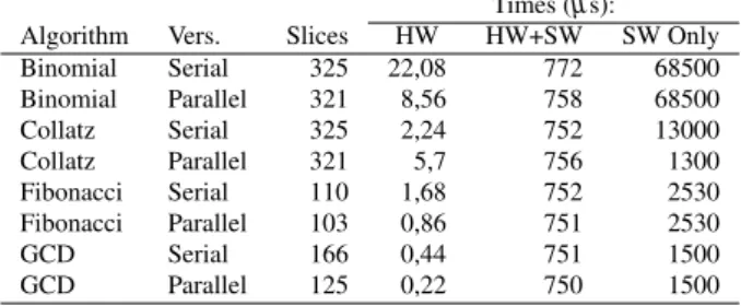
As a test suite, several simple algorithms (taken from [18]) were coded, simulated with Icarus Verilog, and syn-thesized with ISE 12.4 from Xilinx, having as target a Spar-tan 3E FPGA. The results appear on table 2. An interesting result is that for simple algorithms, the parallel evaluation of the conditions, besides being faster, uses less resources. This happens because when evaluating the clauses sequen-tially, some resources are needed to track the current con-dition being tested.
On this type of computational architectures, the highest performance (lower execution time) version is also the ver-sion that uses the minimum of resources, maximizing two of the most pressing constraints for an hardware designer.
The execution times are given for a system with a Mi-croblaze processor at a clock frequency of 50 Mhz, on a Spartan 3E FPGA. They represent in order, the time needed for the implemented hardware core to calculate the desired results from the input data, the time needed for the run-ning Erlang system to make the same task using the im-plemented hardware, and the time needed using a software approach coded entirely in Erlang.
Table 2. Data for sample modules Times (µs): Algorithm Vers. Slices HW HW+SW SW Only Binomial Serial 325 22,08 772 68500 Binomial Parallel 321 8,56 758 68500 Collatz Serial 325 2,24 752 13000 Collatz Parallel 321 5,7 756 1300 Fibonacci Serial 110 1,68 752 2530 Fibonacci Parallel 103 0,86 751 2530 GCD Serial 166 0,44 751 1500 GCD Parallel 125 0,22 750 1500
An additional resource sharing alternative was tested, coding in the same hardware module two different compu-tational blocks, however no resources sharing or execution time benefits were found.
5. Conclusions
There are two subjects of this paper: the tools used and the proposed architecture. The tools used (templates built using a TCL based preprocessor) allowed the prototyping and the reutilization of templates for different computa-tional tasks. The templates also support the automatic in-stantiation of sub-modules, in the cases where an action is too complex to be executed in a single clock cycle. The transparency of the preprocessor (the user has full control over all the code expansion phases) also means that any bugs were easily located and corrected.
The preprocessor was also used for the creation of the testbenches, and the TCL know-how gained was applied in the automatization of common Xilinx synthesis workflows. The flexible design architecture of the computational blocks allows:
1. An architecture suitable for the future automatic trans-lation from Erlang into hardware.
2. The use of different design alternatives for different sub-blocks.
In the future, the used templates will be integrated in a framework for automatically exploring design alternatives, reusing some of this work, providing hardware acceleration on embedded Erlang based systems, with demonstrated ad-vantages.
References
[1] Guy L. Steele Jr. and Gerald Jay Sussman. Design of a LISP-based microprocessor. Commun. ACM, 23(11):628– 645, 1980.
[2] William Stoye. The implementation of functional languages using custom hardware. PhD thesis, Computer Laboratory, University of Cambridge, Cambridge, December 1985. [3] Philip C. Treleaven and Geoffrey F. Mole. A
multi-processor reduction machine for user-defined reduction lan-guages. In Proceedings of the 7th annual symposium on Computer Architecture, pages 121–130, La Baule, United States, 1980. ACM.
[4] Yaohoan Chu. Concepts of high-level language computer architecture. In Yaohan Chu, editor, High-Level Language Computer Architecture, chapter 1, pages 1–14. Academic Press, New York, 1975.
[5] Satnam Singh. System level specification in Lava. In De-sign, Automation and Test in Europe Conference and Exhi-bition, 2003, pages 370–375, Munich, 2003.
[6] Xavier Saint-Mleux, Marc Feeley, and Jean-Pierre David. SHard: a Scheme to hardware compiler. In Proceedings of the 2006 Scheme and Functional Programming Workshop, Portland, Oregon, 2006. University of Chicago.
[7] Rishiyur S. Nikhil and Kathy R. Czeck. BSV by Example. Bluespec Inc., Framingham, Massachusetts, 2010.
[8] Chris Okasaki. Purely Functional Data Structures. Cam-bridge University Press, CamCam-bridge, 1999.
[9] E.A. Lee. The problem with threads. Computer, 39(5):33– 42, May 2006.
[10] Joe Armstrong. Programming Erlang. Pragmatic Book-shelf, Raleigh, NC, 2007.
[11] Paulo Ferreira, Jo˜ao Canas Ferreira, and Jos´e Carlos Alves. Erlang inspired hardware. In FPL 2010 - International Con-ference on Programmable Logic and Applications, pages 244–246, Milano, 2010. IEEE.
[12] David B. Thomas and Wayne Luk. FPGA-Optimised uni-form random number generators using LUTs and shift reg-isters. In Proceedings of the 2010 International Conference on Field Programmable Logic and Applications, FPL ’10, pages 77–82, Washington, DC, USA, 2010. IEEE Computer Society.
[13] Wei Zhang, Vaughn Betz, and Jonathan Rose. Portable and scalable FPGA-based acceleration of a direct linear system solver. ACM Trans. Reconfigurable Technol. Syst., 5(1):6:1– 6:26, March 2012.
[14] Gary Spivey. EP3: An extensible Perl preprocessor. In Inter-national Verilog HDL Conference and VHDL InterInter-national Users Forum, 1998. IVC/VIUF 1998. Proceedings., pages 106–113, March 1998.
[15] Adrian Lewis. Prepro: Embedded Perl/Python preproces-sor. Corner Case Research, 2007.
[16] Koen Van Damme. The G2 Preprocessor, 2002.
[17] John K. Ousterhout. Tcl and the Tk toolkit. Addison Wesley, Reading, Massachusetts, 1994.
[18] Mika¨el R´emond. Erlang programmation. Eyrolles, Paris, 2003.