Nuno Rafael
Mendonça Lourenço
Sistemas de Comunicação com Luz Visível:
Emissor/Receptor
Communication Systems Using Visible Light:
Emitter/Receiver
Nuno Rafael
Mendonça Lourenço
Sistemas de Comunicação com Luz Visível:
Emissor/Receptor
Communication Systems Using Visible Light:
Emitter/Receiver
Dissertação apresentada à Universidade de Aveiro para cumprimento dos requisitos necessários à obtenção do grau de Mestre em Engenharia Electrónica e Telecomunicações, realizada sob a orientação científica do Doutor Dinis Gomes de Magalhães dos Santos, Professor Catedrático do Departamento de Electrónica, Telecomunicações e Informática da Universidade de Aveiro e do Doutor Luis Filipe Mesquita Nero Moreira Alves, Professor Auxiliar do Departamento de Electrónica, Telecomunicações e Informática da Universidade de Aveiro
o júri
presidente Professor Doutor Rui Luis Andrade Aguiar
Professor Associado do Departamento de Electrónica, Telecomunicações e Informática da Universidade de Aveiro
Professora Doutora Guiomar Gaspar de Andrade Evans
Professora Auxiliar do Departamento de Física da Faculdade de Ciências da Universidade de Lisboa
Professor Doutor Dinis Gomes de Magalhães dos Santos
Professor Catedrático do Departamento de Electrónica, Telecomunicações e Informática da Universidade de Aveiro
Professor Doutor Luis Filipe Mesquita Nero Moreira Alves
Professor Auxiliar do Departamento de Electrónica, Telecomunicações e Informática da Universidade de Aveiro
agradecimentos
Nunca tão pequena secção conseguiria conter todas as menções e agradecimentos a todos os que, directa ou indirectamente, contribuíram para a realização deste trabalho. No entanto, e não menosprezando qualquer tipo de contribuição, pretendo desta forma apresentar as minhas menções e agradecimentos aos que, de uma forma mais directa, contribuíram para a realização deste trabalho:Em primeiro lugar aos meus orientadores, o Professor Doutor Dinis Gomes de Magalhães dos Santos e o Professor Doutor Luis Filipe Mesquita Nero Moreira Alves, pela oportunidade apresentada e pela confiança que depositaram em mim. A constante discussão e orientação científica foram uma bússola preciosa para levar este trabalho a bom porto.
Aos colegas do Laboratório de Circuitos e Sistemas Integrados pelo bom ambiente de trabalho. Em particular, ao Mestre Navin Kumar pelas imensamente proveitosas partilhas de conhecimento e pela oportunidade de participar num trabalho reconhecido.
Ao Instituto de Telecomunicações de Aveiro e ao Departamento de Electrónica, Telecomunicações e Informática da Universidade de Aveiro, pelos meios disponibilizados. De uma forma especial, aos técnicos Paulo Gonçalves e Paulo Martins pela paciência e pelos conhecimentos transmitidos na construção de circuitos impressos.
A todos os professores que me incentivaram o gosto pelo conhecimento, em especial na área da electrónica.
Aos meus pais, Lurdes Mendonça e Rafael Lourenço, pelo incondicional apoio e pela fé depositada em mim. Mesmo a custo de um imenso sacrifício pessoal, sempre me proporcionaram as condições necessárias para perseguir o sonho e a realização pessoal. De igual forma, à minha irmã Fátima Lourenço pela motivação, pelo exemplo e pela paciência demonstrada, mesmo nas fases mais difíceis.
À minha família e amigos mais próximos, que de mil e uma maneiras estiveram presentes e me ajudaram durante este percurso. Em especial, aos meus tios Miguel e Lúcia por todo o carinho e apoio, e à dona Fernanda e ao Sr. Elísio por me acolherem de braços abertos.
Aos eternos colegas Hugo, Paulo Cerqueira e Paulo Sérgio, que animaram e enriqueceram de variadas formas o percurso académico. Também, aos colegas e amigos com quem partilhei o Bloco 13.
À Makoto Kan, pelo ambiente de respeito, disciplina e acima de tudo amizade, em especial ao Sensei Jorge Vieira… OSS!
Finalmente à Ana, a minha fonte de inspiração e motivação. Por todo o seu apoio, por todo o carinho, pela imensa paciência e acima de tudo, por todo o seu amor.
palavras-chave
Luz visível, Emissor, Receptor, Díodos emissores de luz, Fotodíodos, Projecto de sistema, Resposta ganho/fase, VIDAS.resumo
A presente dissertação aborda o design de um transdutor optoelectrónico para um sistema de comunicações sem fios que utiliza a luz visível como meio de transmissão. Estes sistemas tiram partido dos conhecimentos tecnológicos existentes sobre sistemas de comunicações sem fios utilizando o espectro dos infravermelhos, e da recente introdução em massa de díodos emissores de luz de elevado brilho em diversas aplicações de iluminação.O trabalho apresentado foi desenvolvido dentro do projecto VIDAS, tendo em conta os respectivos cenários de aplicação propostos. Este projecto visa aumentar a segurança rodoviária através da introdução de sistemas de comunicação com luz visível, para estabelecer ligações veículo-a-veículo e/ou veículo-a-semáforo. Através destas ligações, poderão ser antecipadamente fornecidos diversos avisos de segurança aos condutores.
O estudo do transdutor proposto, começa com uma introdução ao conceito e evolução dos sistemas de comunicação com luz visível. Segue-se uma apresentação do canal de transmissão, na qual são definidos os modelos de emissor, receptor e propagação. São também discutidas as diversas fontes de ruído óptico e suas influências na aplicação pretendida. A restante análise é dividida em dois dispositivos principais, o emissor e o receptor ópticos.
Sobre o emissor, são apresentados os principais blocos funcionais, seguidos de uma exposição das características de diversos díodos emissores de luz e da análise de diferentes topologias de receptor. Para a topologia mais viável de ser implementada, são apresentados diversos resultados de simulação do circuito electrónico.
Do lado do receptor, de forma análoga, são apresentados os diferentes blocos funcionais e as características de diversos fotodíodos. No entanto a experiência do grupo de trabalho levou à escolha de uma topologia de receptor mais específica. Desta, fazem parte diversos módulos, cuja análise e resultados de simulação dos respectivos circuitos electrónicos são apresentados.
De forma a avaliar a performance dos dispositivos propostos, foram efectuados diversos ensaios e respectivas medições. Estes resultados permitiram obter informações sobre o comportamento da componente óptica do sistema. Deste conjunto de informações, diferentes considerações sobre a performance de módulos individuais e do transdutor são apresentadas. Estas permitem concluir sobre a viabilidade do transdutor optoelectrónico num cenário de aplicação real.
keywords
Visible light, Emitter, Receiver, Light emitting diodes, Photodiodes, System design, Gain/phase response, VIDAS.abstract
This dissertation addresses the design of an optoelectronic transceiver for a wireless communication system, using visible light as the transmission medium. These systems take advantage from the available technological expertise on wireless communication systems using the infrared spectrum, along with the recent massive introduction of high brightness light emitting diodes in several lighting applications.The present work was developed within the scope of project VIDAS, regarding the proposed application scenarios. This project aims at increasing road traffic safety by introducing visible light communication systems to establish vehicle-to-vehicle and vehicle-to-traffic light communications. Through these connections, early safety warnings can be provided to drivers.
The study of the proposed transceiver begins with an introduction to the concept and evolution of visible light communication systems. This is followed by the presentation of the transmission channel, in which the emitter, receiver and transmission models are defined. Also, the sources and influences of the various optical noise sources are discussed. The remaining analysis is divided between the two major devices, the optical emitter and receiver.
From the emitter, the main building blocks are presented, followed by an exposition of several light emitting diodes characteristics and the analysis of diverse receiver topologies. In the case of the most viable topology for implementation, several simulation results of the respective electronic circuit are presented.
On the receiver, the main building blocks and the characteristics of several photodiodes are presented in a similar fashion. However, the workgroup experience led to the choice of a specific receiver topology. This is made up of several modules, whose analysis and simulation results for the electronic circuits are presented.
In order to evaluate the performance of the proposed devices, several tests and measurements were made. These results also provided information on the system’s optical component behavior. From this assortment of information, different considerations on the performance of the individual modules, as well as the transceiver are presented. They allow for a conclusion on the viability of the optoelectronic transceiver in a real application scenario.
Dedicatória
Para a Ana… por tudo.Para os meus pais, Lurdes e Rafael… pela oportunidade. Para a minha irmã, Fátima… pelo exemplo.
…e para toda a família e amigos que ao longo dos anos me apoiou e ajudou nesta caminhada académica.
Contents
List of Tables ... iii
List of Figures ... v
Acronyms ... vii
Chapter I ... 1
Introduction
I.i Background ... 2 I.ii Motivation ... 2 I.iii Objectives ... 5I.iv Dissertation structure ... 5
I.v Original work ... 6
Chapter II ... 9
Wireless communication systems using visible light
II.i The history of VLC ... 10II.ii New trends in lighting systems ... 13
II.iii VLC application examples ... 15
II.iv The transmission channel ... 17
II.iv.i Emission ... 17
II.iv.i Reception ... 19
II.iv.ii Line-Of-Sight propagation model ... 20
II.iv.i Noise sources ... 22
Chapter III ... 27
Emitter Design
III.i Emitter description... 27III.ii Light Emitting Diodes for VLC ... 29
III.iii Emitter topologies ... 33
III.iii.i Alternating current topologies ... 33
III.iii.iii Discrete transistor topology ... 36
Chapter IV ... 43
Receiver Design
IV.i Receiver description ... 43IV.ii Photodiodes for VLC ... 45
IV.iii Receiver modules... 48
IV.iii.i Pre-Amplifier behavior ... 48
IV.iii.ii Pre-Amplifier configurations ... 53
IV.iii.iii Low-Pass filter ... 60
IV.iii.iv Voltage amplifier ... 62
Chapter V ... 69
Optoelectronic Transceiver
V.i Design guidelines ... 69V.ii Measurement setups ... 70
V.ii.i Optical emitter ... 70
V.ii.ii Optical receiver ... 71
V.ii.iii Optoelectronic transceiver ... 73
V.iii Experimental results ... 74
V.iii.i Optical emitter ... 74
V.iii.ii Optical receiver ... 76
V.iii.iii Optoelectronic transceiver ... 81
Chapter VI ... 87
Conclusions ... 87
VI.i Future work proposed ... 88
References ... 91
List of Tables
Table 1: Efficiency and lifetime of conventional and semiconductor white light sources [Hai99] ... 14
Table 2: LOS propagation model parameters ... 20
Table 3: HB-LED’s optical characteristics ... 30
Table 4: HB-LED’s electrical characteristics ... 31
Table 5: LED’s switching times measurements [Per07] ... 32
Table 6: Values of electrical current through the HB-LED ... 39
Table 7: Si photodiodes optical characteristics ... 47
Table 8: Si photodiodes electrical characteristics ... 47
Table 9: Preamplifier version 1: gain/phase results ( ) for different values ... 55
Table 10: Preamplifier version 1: gain/phase results ) for different values ... 56
Table 11: Results of the gain/phase response of the preamplifier configurations ... 59
Table 12: Gain/phase results of the filter’s effect on the receiver ... 61
Table 13: Gain/phase results of the voltage amplifier’s effect on the receiver ... 63
Table 14: Experimental values of electrical current through the HB-LED ... 74
List of Figures
Figure 1: The electromagnetic spectrum ... 3
Figure 2: VIDAS Application examples ... 4
Figure 3: The photophone - drawing by Alexander G. Bell and Charles Tainter [Bel80] ... 11
Figure 4: The evolution of performance and cost for commercially available red LED’s [Hai99] ... 12
Figure 5: Luminance of several light sources [Kra07] ... 14
Figure 6: Outdoor VLC application examples ... 15
Figure 7: Indoor VLC application examples ... 16
Figure 8: Normalized Lambertian radiation patterns for = [1, 3, 10] ... 18
Figure 9: Receiver model ... 19
Figure 10: LOS propagation model for VIDAS application ... 20
Figure 11: Normalized spectral power densities of common light sources [Tav99] ... 22
Figure 12: Transmission coefficient of typical IR cut-off filter [EOweb] ... 24
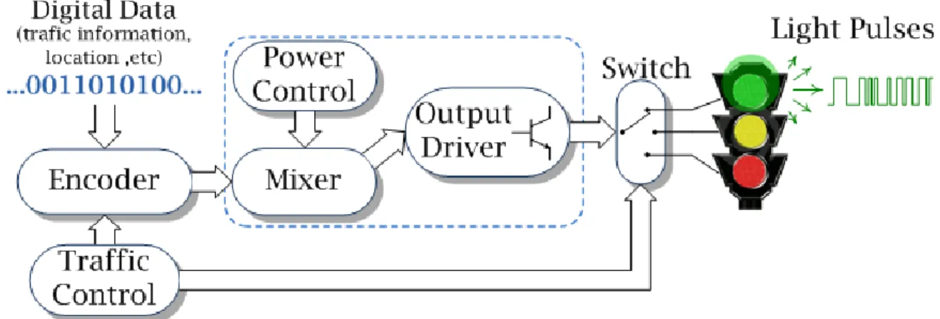
Figure 13: VLC emitter block diagram for a traffic light... 28
Figure 14: Emitter topologies for AC power supply ... 33
Figure 15: Buck regulator with shunt FET circuit ... 36
Figure 16: Discrete current-sink emitter topology ... 37
Figure 17: Emitter: time domain response at different frequencies ... 38
Figure 18: Emitter: gain/phase response ) ... 39
Figure 19: VLC receiver block diagram ... 44
Figure 20: Photodiode electrical equivalent model [Ham03] ... 48
Figure 21: Simplified small signal input stage ... 49
Figure 22: Bode asymptotical gain plot for a first order amplifier ... 49
Figure 23: Bode asymptotical gain/phase plot of a second order amplifier ... 51
Figure 24: Transimpedance amplifier in a shunt-shunt feedback topology ... 51
Figure 25: Bode plot with the intersection of the and curves ... 52
Figure 26: Preamplifier version 1 ... 53
Figure 27: Preamplifier version 1: gain/phase response for different values ... 55
Figure 28: Preamplifier version 1: gain/phase response for different values ... 56
Figure 29: Preamplifier version 2 ... 57
Figure 30: Preamplifier version 2: gain/phase response ) ... 58
Figure 31: Preamplifier version 3 ... 58
Figure 32: Preamplifier version 3: gain/phase response ... 59
Figure 33: Low-pass filter with an input buffer ... 60
Figure 34: Low-pass filter: gain/phase response of ... 61
Figure 35: Filter’s effect on the receiver: gain/phase response of ... 61
Figure 37: Voltage amplifier: gain/phase response of ( ) ... 63
Figure 38: Voltage amplifier’s effect on the receiver: gain/phase response of ... 63
Figure 39: Receiver: DC sweep response ... 64
Figure 40: Emitter characterization: measurement setup ... 71
Figure 41: Receiver characterization: measurement setup for network analysis ... 72
Figure 42: Receiver characterization: measurement setup for spectrum analysis ... 72
Figure 43: Transceiver characterization: measurement setup ... 73
Figure 44: Emitter: LED current measurements at different frequencies... 75
Figure 45: Preamplifier version 1.0: gain/phase ( ) measurements ... 77
Figure 46: Preamplifier version 2.0: gain/phase measurements ... 77
Figure 47: Preamplifier version 3.0: gain/phase ) measurements ... 77
Figure 48: Low-pass filter: gain/phase ( measurements ... 78
Figure 49: Preamplifier v1.1 and low-pass filter: gain/phase measurements ... 78
Figure 50: Preamplifier v2.1 and low-pass filter: gain/phase measurements ... 79
Figure 51: Preamplifier v3.1 and low-pass filter: gain/phase measurements ... 79
Figure 52: Receiver: spectrum analysis measurement ... 80
Figure 53: Transceiver in a dark environment: measurements for different frequencies ... 81
Figure 54: Transceiver at ambience light: measurements for different frequencies ... 82
Figure 55: Transceiver with a close noise source: measurements for different frequencies ... 83
Acronyms
A
AC – Alternating Current
ADAS – Advanced Driver Assistance System AlGaAs – Aluminum Gallium Arsenide
AlInGaP – Aluminum Gallium Indium Phosphide
D
DC – Direct Current
F
FET – Field-Effect Transistor FOV – Field-Of-View
FPGA – Field-Programmable Gate Array
G
GaAsP – Gallium Arsenide Phosphide GBW – Gain-BandWidth product GPS – Global Positioning System
H
HB-LED – High Brightness - Light Emitting Diode HID – High-Intensity Discharge
HP – Hewlett Packard hpa – half-power angle
I
IC – Integrated Circuit
IEEE – Institute of Electrical and Electronics Engineers InGaN – Indium Gallium Nitride
IR – InfraRed
L
LED – Light Emitting Diode LOS – Line-Of-Sight
M
MFB – Multiple FeedBack
N
NRZ – Non Return to Zero
O
OOK – On-Off Keying
P
PCB – Printed Circuit Board PDA – Personal Digital Assistant PIN – Positive-Intrinsic-Negative PLC – Power Line Communications PWM – Pulse-Width Modulation
R
RF – Radio Frequency RGB – Red, Green and Blue
S
Si – Silicon
SMD – Surface Mount Device SNR – Signal-to-Noise Ratio
T
TFFC – Thin Film Flip Chip
U
V
VIDAS – VIsible light communications for advanced Driver Assistance Systems VLC – Visible Light Communication
Chapter I
Introduction
Visible Light Communication (VLC) is a recent technique in the field of wireless communications. As the name implies, light in the visible range of the electromagnetic spectrum is used as the communication medium for data transmission. Although it might seem a revolutionary idea, history has several examples of usage of this medium. Ancient tribes used smoke signals, and there is even the record of Graham Bell’s photophone
[Bel81], an attempt for transmitting information through visible light.
In 1978, Gfeller proposed ―Wireless In-House Data Communication via Diffuse Infrared Radiation‖ [Gfe79], this way laying the stepping-stone to the usage of the optical spectrum in modern wireless data transmission. Although infrared (IR) wavelengths were proposed for both directed and non-directed communications, many of the knowledge and studies done in this area can easily be adapted and re-used for VLC. The used wavelengths are fairly close, which makes propagation models, noise sources and even system design easily adaptable.
The current work focuses on the design of the front-end electronics for a visible light emitter and receiver. For this purpose, the workgroup background and expertise in areas such as wireless IR, VLC and electronic system design were essential in deciding the path to follow.
The current chapter presents the main motivations of this project for researching VLC technologies. The objectives are explained, and a brief description of the dissertation is presented.
I.i Background
The present dissertation “Communication Systems using Visible Light: Emitter/Receiver” is inserted in the area of conceptual investigation for mobile wireless communications using visible light as a transmission medium. In this area of investigation the current work is part of project VIDAS (VIsible light communications for
advanced Driver Assistance Systems) (PTDC/EEA-TEL/75217/2006) [VIDweb] currently
being developed in the Integrated Systems and Circuits laboratory at the Institute of Telecommunications of Aveiro.
Within the compass of this project several studies, which serve as background to the present dissertation, have been performed by the workgroup. In the project report entitled ―Projecto Luz Comunicante‖ referred as [Per07], an initial analysis to the proposed VLC system, along with experimental characterization of several light emitting diodes (LED’s) was performed. In the published article ―Visible Light Communication Systems Conception and VIDAS‖ referred as [Kum08], the state-of-the-art of VLC systems and other VIDAS related research issues were addressed. More recently, a study entitled ―Design and Analysis of the Basic Parameters for Traffic Information Transmission Using VLC‖, referred as [Kum09], was also published, including a deeper system analysis with model description and parameter optimization.
I.ii Motivation
Modern society is highly dependent on information technologies, especially on mobile and wireless products and applications. The evolution of the personal computer towards mobility and portability was essential for this evolution. Devices such as notebooks, personal digital assistants (PDA’s) and cell phones have become part of people daily lives. By changing work habits throughout the world, they played an important role in boosting the growth of wireless communications networks, with some of the most known standards defined by the Institute of Electrical and Electronics Engineers (IEEE) under project 802.11 [802web].
From an early start, wireless radio-frequency (RF) technologies achieved commercial domination in detriment of wireless optical technologies which use the IR spectrum. Although they offer major advantages such as high bandwidth or implementation simplicity, IR based technologies still have some drawbacks, mainly regarding user safety when handling high power signals. IR radiation makes chemical bonds resonate which corresponds to an increase of energy in molecules. This increase is perceived as heat and can have harmful consequences in humans. Even for a moderate amount of IR radiated energy, prolonged exposure over the years can lead to a gradual
opacity of the eye lens, also known as cataracts. These power limitations seriously affect the available data rates and communication ranges, nevertheless optical wireless communications are still highly desirable, and where IR showed its major flaws, VLC presents itself as a viable solution. Visible light also encompasses a relatively wide range of the electromagnetic spectrum, with the advantage of being un-licensed, allowing, at least in theory, larger bandwidth to be explored than in radio based systems. It is safe to humans and does not cause any interference with RF based electronics.
Figure 1 shows a portion of the electromagnetic spectrum. Although the IR range contains wavelengths from around 750nm to 1mm, the actual interval used for data communication is the near-IR which includes wavelengths from 780 to 950nm. Visible light lies in the range of 380 to 750nm. These two ranges are very similar, which means that most of the advantages of wireless IR systems are also present in VLC systems, and light behavior will be similar. Therefore, the research for techniques and models of communication systems using the visible range of the electromagnetic spectrum appears as a viable alternative. Such models and techniques can easily be adapted from the extended studies already available on IR communication systems.
In order to become practical, thus standing a chance of becoming a leading technology, VLC systems will need to take into account several drawbacks. Probably the most important is the need to coexist, and not be affected by, existing lighting systems, while not interfering, or being interfered by, current radio based wireless technologies. This could hardly be achieved by using conventional light sources, such as incandescent or fluorescent lights, the alternative lies on solid state lighting. LED’s present a number of advantages over conventional light sources that makes them the ideal component for VLC systems, with the most important being the fact that any LED is a semiconductor, and therefore as an inherent fast switching ability. Along other advantages are also high energy conversion efficiency, larger lifetime, humidity tolerance and an overall low maintenance cost.
By reaching performances easily comparable to conventional light sources, the new high-brightness light emitting diodes (HB-LED’s) have reached new lighting markets and can be found in applications as diverse as indoor and outdoor general lighting, large size advertising boards, interior and exterior automotive lighting or traffic semaphores, also known as traffic lights. All of these applications are also different possibilities for a VLC system, with the final two being determinant to the implementation of VIDAS.
For long, road traffic safety has been a major concern for the authorities, with the European Union setting challenging targets for its improvement until the year 2010. Currently, several projects that aim to improve road traffic safety, such as AIDE-IP, PREVENT-IP or SAFESPOT-IP, are being supported by the European Union. Also, the daytime running lights proposal, which intends for motor vehicles to travel with their lights turned on at all times, has been opened for discussion and is expected to be implemented in the close future [VIDweb]. With this background, and taking advantage
from the increasing usage of HB-LED’s, in traffic lights and vehicle external lighting, the VIDAS project was introduced.
Presenting itself as a complement to the existing advanced driver assistance system (ADAS), VIDAS proposed the usage of outdoor illumination to increase road traffic safety. This is to be achieved by studying VLC as a possible solution for implementing a communications system for vehicle-to-vehicle and/or vehicle-to-traffic lights, as represented in figure 2. This way, early warnings regarding collision avoidance, intersection information, speed control, along with others, can be provided to drivers, thus helping reduce road traffic accidents and fatalities. Another possibility of VIDAS is the optimization of traffic flow by establishing an interactive navigation support system, using traffic lights as information broadcasters [VIDweb].
I.iii Objectives
The main objective presented for this dissertation, was to study and develop an optoelectronic transceiver for a VLC application, specifically for the VIDAS project. The tasks proposed in order to achieve this objective were:
Study and understand the concepts of VLC;
Study and research transceiver devices (LED’s and photodiodes) for the desired application;
Design and prototype a VLC emitter and receiver; Characterize the developed prototypes;
Characterize the optoelectronic transceiver.
I.iv Dissertation structure
The current dissertation is divided into six chapters. The current chapter starts with a small introduction on VLC and follows, in subsection I.i, with the background that led to the work developed. Subsection I.ii gives a more insightful look on the motivations for developing this study, followed by its primary objectives in subsection I.iii. A summary on the structure of this text is given in this subsection, followed in I.v with a description of original work produced.
Chapter II is divided into four subsections. It is dedicated to introducing the concept of wireless communication systems using visible light, and starts in subsection II.i by presenting the history of VLC. In order to further explain the dissemination of HB-LED’s subsection II.ii shows the new trends in lighting systems, followed by some VLC application examples in subsection II.iii. The transmission channel is also analyzed in this chapter, in subsection II.iv. It is divided into four parts, in which the emission, reception and line-of-sight propagation models are presented, along with an analysis of the most important noise sources and its influences on the VLC system.
Chapter III is fully dedicated to the analysis of the VLC emitter design. It starts in subsection III.i with a description on the receiver main building blocks. In subsection III.ii, the characteristics of several researched LED’s, that could be used in VLC, are presented and discussed. The final subsection, III.iii, is divided into three groups of implementation topologies. In the first group, of alternating current topologies, the implementation schemes of some configurations are presented and discussed. In the group of HB-LED driver topologies, the concept of using this type of already built devices to implement a VLC emitter is discussed. Finally a discrete transistor topology is analyzed, by presenting simulation results and some practical considerations.
In a similar way, chapter IV is dedicated to the analysis of the VLC receiver, and is also divided into three subsections. Starting in IV.i a description of the main building blocks is presented. The research results on several photodiodes for VLC and their most important characteristics are presented in subsection IV.ii. The final subsection, IV.iii, presents the analysis of the different modules of the receiver. Simulation results and considerations are made for the preamplifier, the filter and the voltage amplifier.
Chapter V is a chapter dedicated to presenting the experimental results of the implemented devices. Starting in subsection V.i, the design guidelines followed in the development of the several prototypes built is presented. In subsection V.ii the setup measurements used to obtain the experimental results are presented, and in subsection V.iii, the respective experimental results for the optical emitter, optical receiver and optoelectronic transceiver are shown and discussed.
In chapter VI, the conclusions reached during the execution of this dissertation are presented. Several considerations on the obtained results and guidelines followed are made, as well as indications for future improvements to the developed devices.
I.v Original work
During the execution of the work presented in this dissertation the article entitled ―Visible Light Communication Systems Conception and VIDAS‖ was submitted to the Institute of Electronics and Telecommunications Engineers Technical Review (IETE Technical Review), to be published. The article addressed several research issues and ideas related with VLC and project VIDAS, which were being explored at that time. Namely, the state-of-the-art of VLC systems, implementation issues in indoor and outdoor scenarios, possible applications and system design. With most of the credit going to the author, Mr. Navin Kumar, I was given the opportunity to collaborate by writing about some of the implementation aspects of a wireless USB application, especially the emitter and receiver design. Recently the article was awarded with the IETE – Gowri Memorial Award (2009) for the best paper on topic of general interest.
Chapter II
Wireless communication systems
using visible light
“I have heard articulate speech by sunlight!
I have heard a ray of the sun laugh and cough and sing! ” Alexander Graham Bell, in a letter to his father
Communication systems have become the backbone of our “information society”. From the beginning, RF-based systems dominated the wireless applications world, but eventually began to reach a saturation point. This made alternatives highly desirable, leading to the introduction of IR wireless technologies [Gfe79]. Although presenting several
benefits over RF, IR never became a mainstream technology. However, optical wireless technologies are still highly desirable, and with the affirmation of HB-LED’s as the lighting technology for the future, visible light spectrum became a viable alternative [Pan02, Cra95].
HB-LED’s have reached, among others, automotive lighting and traffic light applications, thus making the usage of VLC in ADAS a possibility, of which VIDAS is an example. It becomes necessary to define specific emission, propagation and reception models, as well as to analyze the influence of different noise sources [Tav99, Kum08, Kum09].
This chapter begins with an introduction to the history of VLC in subsection II.i. LED applications and advantages are presented in subsection II.ii, followed by the application possibilities for VLC systems in subsection II.iii. The line-of-sight model of the
optical link is presented in subsection II.iv, with emission, propagation and reception models analysis. The noise sources that affect this application are also presented.
II.i The history of VLC
The importance of communication systems in today’s society hardly needs to be emphasized. Every day, information, economical, financial, transportation and other important systems depend on the fast and reliable access to information. People need it to be everywhere, easily and quickly available. This has been made possible through the evolution of portable devices and the arrival of wireless communications.
Modern wireless communications have been dominated by RF-based technologies. They are used on a daily basis in things such as cell-phone communications, computer wireless networks (Wi-Fi), global positioning systems (GPS), etc. But despite their widespread use, RF-based technologies present considerable limitations. With the frequency range for RF wireless systems being strictly regulated, it is not always possible to obtain licenses to implement new communication networks. Also, radio signals travel freely, with obvious consequences on information security. And in some cases, data encryption can be resource demanding on a secured wireless network. Another problem occurs when trying to use RF-based positioning systems like GPS. Not only its precision is limited, but it is also practically impossible to use inside a building, especially in basements or underground parking lots. Therefore, it becomes highly desirable to find alternatives to RF wireless systems.
IR wireless technologies were presented as an alternative for the RF based systems
[Gfe79], offering several benefits in bandwidth, implementation simplicity and data
security, among others [Kah97]. However, they never became a mainstream technology.
Constraints to the levels of radiated energy, regarding user health, seriously limited the data rates or communication ranges of commercially available devices. However, optical wireless technologies still play an important role in future developments.
Some of the earliest references to a communication system using visible light come from ancient tribes, which used smoke signals to convey information, or from the ancient Greeks, who used their polished shields to transmit messages by reflecting sunlight. But the first reference to conceptual investigation and prototype building of a VLC system comes from the father of the telephone, Alexander Graham Bell. On the 3rd of June of 1880, Alexander Graham Bell and his assistant Charles Tainter succeeded in transmitting the world’s first wireless telephone message over a distance of 213 meters. Their design used the sunlight as source, which was modulated through the vibration of a reflecting
mirror and then captured in a parabolic mirror with photoconductive selenium cells at the focal point [Bel81, Hra05]. A drawing of the design is presented in figure 3.
In spite of this early discovery, VLC was overtaken by the advances in both wired and RF communications, with the help of great names like Hertz, Bell, Edison and Marconi along with many others. However, history has several major breakthroughs on record in the area of VLC. In the mid-1920’s, Oleg Vladimirovich Losev, who worked as a technician in several radio laboratories in the former Soviet Union, observed light emission from zinc oxide and silicon carbide crystal rectifier diodes, when a current was passed through them. These were used in radio receivers. Losev realized the potential in his discovery and invented the first LED. Further, on December 31st 1929 he wrote:
“The proposed invention uses the known phenomenon of luminescence of a carborundum detector and consists of the use of such a detector in an optical relay for the purpose of fast telegraphic and telephone communication, transmission of images and other applications when a light luminescence contact point is used as the light source connected directly to a circuit of modulated current.”.
With this plan of thought, Losev could have started the revolution of optical communications, but he died young and unrecognized [Zhe07]. It was only in 1962 that
Nick Holonyak Jr. created the first practical red LED, after inventing a method to synthesize Gallium Arsenide Phosphide (GaAsP) crystals, which exhibited wavelengths in the visible spectrum [Perr03]. In the following years the efficiency of red LED’s increased
significantly, and the first commercially available LED’s were presented by Monsanto and Hewlett Packard (HP) in the late 1960’s. These devices exhibited very low efficiency, about 0,1 lumens of output flux per watt of input electrical power. They were mainly used as indicators in indoor applications. In 1968 another technological breakthrough occurred
with the addition of nitrogen which led to the first orange and yellow LED’s, and in the early 1980’s the arrival of red Aluminum Gallium Arsenide (AlGaAs) devices, with efficiencies of the order of 2 to 10 lumens per watt (lm/w), the LED’s reached new markets, such as the automotive taillights, or outdoor moving message boards. In 1990, P. Kuo and his co-workers presented their new yellow Aluminum Gallium Indium Phosphide (AlInGaP) LED’s with performances comparable to the best red AlGaAs devices, and the color range of high brightness was almost complete [Cra95]. Blue was the missing
color but, in 1992, Shuji Nakamura presented the first blue HB-LED. He was somewhat isolated from the mainstream of industrial research. When the industry had already dismissed the Indium Gallium Nitride (InGaN) alloy, he persevered and took one of the most important steps into the revolution of solid-state lighting. Given that blue LED’s are the base for white light HB-LED’s [Rio07]. With the growing evolution in optics,
semiconductor devices and materials science, LED technologies have been growing in an exponential way. Since the 1960’s LED’s have doubled their light output and power efficiency every 36 months. This behavior became known as “Haitz’s Law” [Hai99] and it is
shown in figure 4. These numbers confirm the penetration of LED’s into the market of lighting systems, not only in automotive applications, but also in city outdoor lighting, home indoor lighting, etc.
Another important foundation to VLC was the IR wireless communications systems presented by Gfeller in [Gfe79]. Although IR never became a complete alternative to RF in wireless communication systems, it presents itself as a complementary technology with several advantages. The used spectral interval of 780 to 950nm permits the use of a virtually unlimited bandwidth that is unregulated worldwide; IR emitters and
Figure 4: The evolution of performance and cost for commercially available red LED’s [Hai99]
detectors capable of high-speed operations are available at low cost; data transmission can be confined with an opaque obstacle, thus reducing interference between links and ensures data security from outside access; if intensity modulation and direct detection are used, the smaller wavelengths combined with a large-area, square-law detector leads to efficient spatial diversity that prevents multipath fading. This factor allows the usage of much simpler designs than those used by RF, which is frequently subject to large fluctuations in signal amplitude and phase. However, in a free space optics communication channel, restrictions to these considerations need to be applied, especially on the available bandwidth.
Due to the advances in the field of solid-state lighting, HB-LED’s have become available in all color ranges. White HB-LED’s present themselves as the future of both indoor and outdoor lighting scenarios. By joining the penetration of HB-LED’s in our daily lives, and the knowledge available on IR wireless communications, VLC presents itself as a promising technology for the future of wireless communications. It is a ubiquitous technology, generating no interference to human life or existing electronic devices. Unlike RF systems, VLC can be used in hospitals, space stations and other electromagnetic interference sensible locations. Applications such as visible light communication for audio systems [Pan99], information broadcasting using LED traffic lights [Aka01, Kum08, Kum09] and integration of VLC with power-line communications (PLC) [Kom03], are examples
of the capabilities of VLC. One of the most important steps towards standardization was made with the establishment of the Visible Light Communications Consortium, a group of mostly Japanese based companies that agreed on sharing information towards the development of this new technology [VLweb]. Another signal of the importance of VLC was
the creation of the task group seven (TG7) under the IEEE 802.15 working group for wireless personal areas networks [IEweb].
II.ii New trends in lighting systems
Visible light LED’s have had a huge development since their days of simple indicators. The main reason for this was the great increase in efficiency and the decrease in production cost [Kra07]. In figure 5 is presented a chart on the evolution of luminance
values of LED’s and a comparison with some of the effective luminance values of conventional light sources: tube fluorescent, automotive halogen, automotive Xenon high-intensity discharge (HID), and ultra-high-performance (UHP) discharge lamp used for projection. LED values are color-coded to the correspondent wavelengths, and white LED’s with the Thin Film Flip Chip (TFFC) technology from LUMILEDS are marked as triangles. On the right of the image are the ranges required for several applications [Kra07].
In table 1 the typical efficiency and lifetime values of common white light sources, are shown, as along with the predicted values for white light LED’s around the year 2000
[Hai99]. Although the values are an optimistic prediction for white light LED’s, actual
Luxeon Rebel LED’s achieve values of 100lm/W, and a lifetime of 50.000 hours with 70% lumen maintenance, when driven with a current of 700mA. And the state-of-the-art Luxeon K2 LED’s can achieve over 200lm/w, and a lifetime of 50.000 hours with 70% lumen maintenance, when driven with a current of 1A.
In the United States of America, about a third of the electrical power is spent in lighting applications, with incandescent and fluorescent lamps being the most usual devices encountered. With power-efficiency and cost-reduction as the main concerns, white-light LED’s become a perfect solution for future lighting scenarios. LED’s, unlike conventional light sources, provide direct conversion of electrical energy into light, meaning that most of the energy is used for lighting and not dissipated through heating.
Table 1: Efficiency and lifetime of conventional and semiconductor white light sources [Hai99]
Lamp Type Efficiency [lm/W] Lifetime [h]
100W Incandescent 15 1 000
135W Long Life Incandescent 12 5 000
300W Halogen 24 3 000
50W Compact Halogen 12 2 500
11W Compact Fluorescent 50 10 000
30W Fluorescent 80 20 000
White LED (Year 2000) 20 100 000
White LED (Year 2002) 30 100 000
White LED (Year 2005) 40 100 000
White LED (Year 2010) 50 100 000
(LED’s efficiency values as projected in [Hai99])
They are also much more robust devices, with higher tolerance to humidity, lower heat generation and longer lifetimes, thus the cost of replacement is dramatically reduced. The size of the LED’s is also a great advantage. However, it has the adverse effect of concentrating heat, especially on HB-LED’s, but this can be offset by dissipating heat through the fixture. Also, current packaging technologies open an array of heat dissipation possibilities, making the design of LED lighting systems easier as time passes. Arguably, LED’s are also much more aesthetically pleasing [Kra02, Kra07, Shu05]
A major application for colored LED’s is traffic light substitution. The increased seeing distance achieved with today’s HB-LED’s makes these devices easy to adapt. Color conversion is straightforward, without the necessity for a colored lens, thus simplifying the design. Also, on an outdoor scenario, white light LED’s can easily be adapted to street lighting, with a better light distribution, the same is valid for indoor lighting. Special Red, Green and Blue (RGB) LED’s are also used in outdoor billboards and giant screens with remarkable performance. In all of these applications, using LED’s means lower power consumption, leading to less greenhouse gas emissions due to electrical power production in fossil-fuel burning power plants.
II.iii VLC application examples
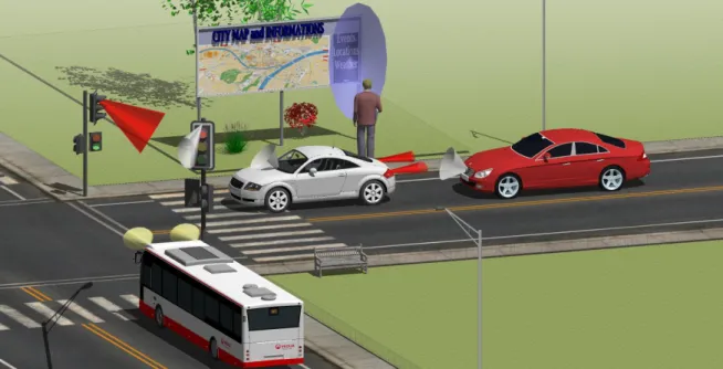
All the new applications for HB-LED’s have made possible to implement VLC systems in different scenarios. In figure 6 some of the outdoor scenarios are illustrated. All the vehicles, traffic lights and billboard use HB-LED’s and are equipped with VLC systems. On the bottom left corner a bus passes through an intersection transmitting its
identification to a receiver mounted on the traffic light, this information is then relayed to a control station where a supervisor can verify the bus location or even if it is on schedule, without having to resource to an RF based GPS system. This is a clear example of an Intelligent Transportation System (ITS), which can also be used in automated tollbooths in similarity to what happens with the Portuguese system ―Via-Verde‖. In the centre of the figure the white vehicle is receiving information from the traffic light, this information could be related to traffic conditions ahead, GPS location, etc. Also in the white car, the taillight is sending information to the vehicle behind it, transmitting that it has stopped so, even if the driver of the red vehicle fails to use the brakes, the onboard computer will stop the red car automatically. This is an example of an ADAS, which can be easily implemented through VLC. These are the type of applications that project VIDAS is trying to develop. One final application is shown in the background, a person can point a VLC equipped portable device to a billboard and automatically receive relevant information from it, such as a map or even advertisement. Not shown on the figure is the possibility of using the street lighting system as access points, creating a global network throughout a city, for sharing relevant local information.
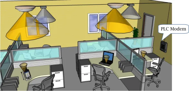
In an indoor scenario VLC applications are mostly focused to network access. In figure 7 is presented an example of an office network using HB-LED’s lighting with VLC and a PLC modem, similar to what is discussed in [Kom03]. The cones in the ceiling represent an approximation to the emission radiation patterns (bright-yellow) and the receiver field-of-view (grey), in the case of the terminals (laptops, desktops and PDA’s), given the proximity of emitter and receiver, a single cone is drawn (dark-yellow). In such a scenario it is possible to see a laptop and a personal computer accessing the network through either inbuilt or USB adapters. VLC networks are contained inside opaque walls
Figure 7: Indoor VLC application examples
and the usage of a PLC modem, as shown in the right of the figure, allows the usage of the already implemented electric cables as a mainframe to interconnect different rooms. Also if each emitter is referenced to the respective GPS coordinates it allows the usage of GPS inside buildings with higher resolution and precision then the current RF based ones.
In conclusion, with the increasing usage of HB-LED’s, the implementation of VLC systems can be adapted to almost any scenario. The Visible Light Communications Consortium and the IEEE 802.15 Task-Group 7 have published information on such applications. As examples are a location-information system from a traffic signal developed by ―The Nippon Signal Co., Ltd‖ and a merchandise information delivery system, in which an intelligent shopping cart displays information about a product or promotions available at a specific area in a supermarket, developed by ―NEC‖ and ―Matsushita Electric Works‖ [Har08].
II.iv The transmission channel
In the current work the transmission channel is defined as the physical space included between the optical emitter and the optical receiver. Its analysis can be broken down into the analysis of three distinct parts, the emitter radiation pattern, the optical signal propagation model and the receiver optical characteristics. Given the similarity of the transmission medium used in VLC and IR systems, the knowledge acquired from the vast research in IR systems can be adapted to VLC. In a recently published paper Kumar describes the VIDAS application scenario and presents a Line-of-Sight (LOS) model for signal propagation [Kum09]. This work along with [Val95] and [Tav99] are the basis
references used in the analysis of the transmission channel. II.iv.i Emission
The basic emitter is constituted by a visible light source modulated to transmit data. Given the specificity of the project, such emitter is based in HB-LED’s which can be individually modeled by a Lambertian radiation pattern having rotational symmetry. Usually in traffic lights, each signal (red, yellow and green) consists of a tight packaging of multiple LED’s, resulting in a radiation pattern equal to the superposition of the individual components, but given the close arrangement of the LED’s a simple Lambertian distribution is assumed for simplification purposes, therefore the radiation pattern is:
0,5 0,25 0 -0,25 -0,5 0,2 0,4 0,6 0,8 1
φ
m=1 m=3 m=10R
(φ
,m
)
Ewhere is the transmitted power, is the direction angle relatively to the emitter’s normal, and is the mode number of the radiation lobe which specifies the directionality of the source and it is given by:
. (eq. 2)
In equation 1, the coefficient is a normalizing factor which ensures
that integrating over the surface of a hemisphere results in the source
power , usually supplied in the device’s datasheet. From equation 2, the directivity of
the emitter is related to the half-power-angle , which represents the viewing angle at
which 50% of the radiant energy is contained, in a plane that contains the lobe’s maximum value, also known as half-power beam-width. This value is usually supplied by LED manufacturers. A mode number of = 1 ( = 60º) corresponds to an ideal Lambertian source. Figure 8 shows a polar plot of the normalized radiation patterns of Lambertian LED’s for directivity values of = [1,3,10], which corresponds to
values of 60º, 35,5º and 21,1º respectively.
To complete the model it is also necessary to specify the position and orientation of the light emitter, relatively to the system’s origin. Position is defined by the geometric
coordinates and orientation is given by the elevation angle . The emitter can
be then defined through:
. (eq. 3)
II.iv.i Reception
Signal reception is done using a PIN photodiode. This converts the optical signal into an electrical current which is further enhanced by a front-end amplifier. A typical receiver model is represented in figure 9. Its key parameters are the field-of-view (FOV)
and the effective signal collection area , which are related by:
, (eq. 4)
where is the physical area of the detector and the angle between the receiver’s axis
and the direction of the incident light.
The FOV represents the maximum value of for which the receiver can still detect light. In a single cell receiver with a photodiode characterized by a FOV of , the receiver is said to have a complete field-of-view, decreasing this value can be used to improve the detection capabilities by cutting off unwanted reflections and noise.
Similar to the emission model, the reception model will only be complete by defining the position and orientation of the receiver relatively to the system’s origin. Position is defined by the geometric coordinates and orientation is given by the
incident angle , resulting in:
. (eq. 5)
At this stage, optical filtering should also be considered. As will be further explained in subsection II.iv.i, a PIN photodiode has a spectral sensitivity that includes a large part of the near-IR spectrum. Given that there are several noise sources that not only affect the visible light spectrum, but also the IR spectrum. If a simple IR cut-off filter is used, the effect of such noise sources can be significantly reduced. From [Mor96], the
transmission coefficient of an optical filter can be broken down to several components, but for now it will be defined as . So, the receiver model with optical filter is now defined by:
. (eq. 6)
II.iv.ii Line-Of-Sight propagation model
The LOS propagation model requires that the emitter has an unobstructed view to the receiver. This model is often used to describe optical wireless communication systems, namely IR connections. It helps explain the behavior of optical signals. Although the following text will address the VIDAS application, the presented model can be applied to any other optical wireless communication system that uses LOS to establish a connection between emitter and receiver.
The VIDAS application relies mostly on the LOS propagation model. The system setup is presented in figure 10. The emitter, a traffic light consisting of an array of HB-LED’s is placed at a given height aligned with the traffic lane with a vertical inclination of , maintaining a direct link between the emitter and the receiver. The
Table 2: LOS propagation model parameters
Parameter Symbol
Distance between receiver and emitter d
Distance in the ground plane x
Height of the traffic light h
Service area Angle of irradiance
Vertical inclination of the receiver FOV of the receiver
Angle of incidence
vehicle with a built-in receiver moves towards the emitter with a certain speed on the ground plane, the receiver is mounted with a vertical inclination of . The interval
between and is the range for possible communication (service area), with
being the nearest point to the traffic light, and the starting point from where data
transmission starts. For quick reference, table 2 contains the system parameters used. In this configuration, the incident power collected in the photodiode at the receiver front-end depends on the transmitted power, on the geometry between the traffic light and the vehicle, on the channel attenuation and on the receiver model. The LOS model can be adapted from wireless IR studies, Kahn and Barry in [Kah97] presented a model in which the intensity of the received signal is given by:
. (eq. 7)
The term represents the delay due to channel propagation, and equation 7 can be
written as a function of with simple trigonometry manipulation. From the right
angle triangle:
, (eq. 8)
, and (eq. 9)
. (eq. 10)
Substituting equation 10 in 9, gives:
. (eq. 11)
Finally the angle of irradiance can be represented as:
. (eq. 12)
This way, considering a normalized emitted power, equation 7 can be written in the format:
. (eq. 13)
This result is available in [Kum09] with further analysis into the optimization of the system parameters. Although it falls out of the scope of this dissertation, it is still a valuable reference for the design of the front-end electronics for VIDAS, or any similar VLC systems.
Sp ec tr al P ow er D en si ty 1 0,8 0,6 0,4 0,2 0 0,4 0,6 0,8 1,0 1,2 1,4 wavelength (μm) Sunlight Incandescent Lamp Fluorescent Lamp Spectral Sensitivity of Si Photodiode Visible Range II.iv.i Noise sources
Noise sources are an important challenge to overcome towards the feasibility of VLC systems. In figure 11, spectral power densities of natural and artificial light sources are compared against the spectral sensitivity of typical silicon (Si) photodiodes. Although there are usually sources of external electromagnetic interference in both the emitter and receiver, mainly due to other electronics devices and the power supply grid, their contributions are small and the effects can easily be minimized by recurring to correct shielding of the front-end electronics and filtering of the power supplies. The major contributions of noise are present in the receiver’s photodiode. These are: thermal noise; shot noise; and optical excess noise.
Thermal noise is associated with the photodiode’s polarizing resistor, and is considered a white noise source with small spectral density. As for shot noise, natural and artificial light sources create a steady background irradiance which causes quantum noise due to the random nature of the photo-detection process. The steady background irradiance induces a constant current on the receiver’s photodiode, usually known by photocurrent. Sunlight’s radiant intensity presents slow variations and can be considered
stationary, the induced photocurrent is represented by , but radiant intensity
produced by artificial light sources presents a periodic component. In the case of incandescent lamps and fluorescent lamps with conventional ballast, the electric noise spectrum shows harmonics in multiples of the double of the power grid’s frequency. The electrical noise spectrum of fluorescent lamps with electronic ballasts shows harmonics in multiples of the power grid’s frequency and in multiples of the ballast’s switching frequency. Also, fluorescent lamps emit a burst of pulses in each period with short length and random starting points, thus inducing a variable photocurrent [Val95, Mor96, Mor97]. Therefore the induced noise photocurrent is given by:
. (eq. 14)
A usual simplification made to calculate the shot noise is to consider the average
value of , thus becomes the average current in the photodiode due to shot noise,
making the optical channel an additive white Gaussian noise. The variance of the shot noise is proportional to this current and is defined by [Val95]:
, (eq. 15)
where is the electronic charge, and is the equivalent noise bandwidth factor.
The average current in the photodiode can be related to the optical power density (optical power per unit of surface area), also known as irradiance through:
, (eq. 16)
where R is the responsivity of the photodiode, and the effective signal-collection area. With the results of equations 15 and 16 it is now possible to specify the Signal-to-Noise Ratio (SNR) of an optical connection in free-space with dominating shot noise:
, (eq. 17)
where and are the signal and noise irradiance respectively. From this expression, is
possible to understand that the value is very important in order to achieve a high SNR [Val95].
Optical excess noise presents a spectral density concentrated in the low frequency range. Its effect can be considered as random fluctuations with a magnitude one hundred times higher to that of the detected data signal [Kum09]. In a VIDAS application scenario, a
headlight of another vehicle circulating in the opposite lane, or even a street lamp, could cause an excess of optical signal in the receiver’s photodiode.
Typical background noise is associated to shot noise, which can be reduced by controlling the amount of background radiation collected. In a free-space optical receiver the FOV and optical bandwidth determine the amount of radiation collected, therefore using a narrower FOV and an optical IR cut-off filter is a desirable solution.
Figure 12 represents the typical response of an IR-cut-off filter [EOweb]. Using this
filter would reduce in approximately 5% the perceived input signal. However, the considerable attenuation provided to any IR component can significantly improve the receiver immunity to the IR component of optical noise sources. In order to better characterize the optical filter, the transmission coefficient can be defined as the sum of several parcels, one for each different light contribution [Mor96]:
where , , and are the transmission coefficients for the transmitted signal, time varying artificial light, average artificial light and natural sunlight, respectively.
Although an optical filter might seem as an excellent solution for reducing noise interference, the price of such component is considerably high, especially when trying to build a cost effective solution. For example, an IR cut-off filter with 12,5mm of diameter costs at about 40€ [EOweb]. Another possible solution would be to use a photodiode that
already includes an IR cut-off filter. These devices are made with a special coating over the photosensitive area that blocks IR light from reaching it. They are intended for visible light applications and usually have a smaller responsivity due to that same coating.
Other sources of noise in outdoor VLC systems, VIDAS in particular, are the unpredictable weather conditions. These can seriously limit the range or even the availability of a data link. The optical signal is subject to absorption due to the presence, in the atmosphere, of water and carbon dioxide particles. Also, by deflecting light, fog, haze, rain or snow cause scattering, which can be minimized by increasing the receiver’s FOV. This can be achieved by using a concentrating lens or increasing the number of receiver cells, although the second solution is not practical in VIDAS or any other ADAS application, and in any case increasing the FOV has its disadvantages.
In conclusion…
VLC had a significant evolution over the last few years. Although the concept of using visible light is very old, it was only in recent years that it became a viable technology for a modern wireless optical communication system. Amongst the several factors that propelled VLC, the introduction of IR communications by Gfeller in [Gfe79] and the recent developments in solid-sate lighting are the most important.
HB-LED’s have reached new performance standards that make them ideal for outdoor and indoor lighting. This opened the doors to a variety of application scenarios, where VLC can also be applied. One of these applications was proposed by project VIDAS and will be developed in this dissertation.
In order to better understand the behavior of the optical signals, receiver, emitter and propagation models were analyzed. Using the widespread knowledge available for IR communications, these models can easily be obtained. The emitter is characterized as having a typical Lambertian radiation pattern which is mostly defined by the half-power angle. The receiver is characterized by its effective signal collection area which is related to the FOV, physical area and the angle of the incident light. With these elements defined, the propagation model can be presented. Similar to many wireless optical communications, the VIDAS application relies on the LOS propagation model. One of the most important conclusions taken from this model is that the optical signal will decrease with the increase of the distance elevated to the square (equation 7).
Another important analysis to VLC systems is the presence and influence of optical noise sources. It is possible to conclude that artificial and natural light sources might create a significant interference to the receiver. Not only do they create a steady background noise, but fluorescent lights also have a transient component that might spread over several decades of frequency, thus causing a significant interference to the transmitted optical signal. Another important conclusion taken from the study of noise sources is that, in order to increase the SNR a device with a large active area should be used.
Chapter III
Emitter Design
A VLC emitter is an optic-electronic transducer device that transmits information using visible light waves as the transmission medium, usually with the resource to HB-LED’s. VLC systems have become a more viable technology for the future of wireless data transmission, in large part due to the developments in the area of solid-state lighting. It becomes pertinent to study the light emitting devices and the different emitter topologies in order to obtain a better performance from a VLC emitter. The VIDAS application scenario presents its own specific obstacles and challenges to which the studied topologies were directed.
This chapter is organized in three subsections. Starting in III.i, the emitter device is defined by presenting the main building blocks. In subsection III.ii, HB-LED’s are analyzed, electrical and optical characteristics are presented as well as some results previously obtained in the laboratory. In the final subsection, III.iii, the studied emitter topologies are presented and discussed.
III.i Emitter description
History has several examples of light emitting devices used to transmit messages. The shields of the ancients Greeks, the mirror in Alexander G. Bell’s photophone [Bel81]
and even flashlights, which are still used. This makes visible light a viable option as a transmission medium. A natural or artificial light source or a light reflector is the only device needed. However, an actual “of-the-shelf” VLC emitter is still some steps away.

![Figure 3: The photophone - drawing by Alexander G. Bell and Charles Tainter [Bel80]](https://thumb-eu.123doks.com/thumbv2/123dok_br/15935230.1095574/25.892.135.780.122.405/figure-photophone-drawing-alexander-bell-charles-tainter-bel.webp)
![Figure 4: The evolution of performance and cost for commercially available red LED’s [Hai99]](https://thumb-eu.123doks.com/thumbv2/123dok_br/15935230.1095574/26.892.179.691.783.1091/figure-evolution-performance-cost-commercially-available-led-hai.webp)
![Table 1: Efficiency and lifetime of conventional and semiconductor white light sources [Hai99]](https://thumb-eu.123doks.com/thumbv2/123dok_br/15935230.1095574/28.892.183.694.133.456/table-efficiency-lifetime-conventional-semiconductor-white-light-sources.webp)