for an Industrial Robotic Application
Rodrigo Bernardo1, Rodolfo Farinha1, and Paulo J.S. Gon¸calves1,2
1 Instituto Polit´ecnico de Castelo Branco, Escola Superior de Tecnologia,
Av. Empres´ario, 6000-767 Cast. Branco, Portugal [email protected],
WWW home page: http://pessoas.ipcb.pt/paulo.goncalves/
2 IDMEC, Instituto Superior T´ecnico, Universidade de Lisboa,
Av. Rovisco Pais, 1049-001 Lisboa, Portugal
Abstract. The paper presents an implementation of knowledge repre-sentation and task reprerepre-sentation, based on ontologies for an Industrial Robotic Application. The industrial application is to insert up to 56 small pins, e.g., sealants, in a harness box terminal for the automotive indus-try. The number of sealants and their insertion pattern vary significantly with the production requests. Based on the knowledge representation of the robot and also based on the tasks to be performed, plans are built and then sent to the robot controller based on the seal pattern production or-der. Moreover, the robotic system is capable to perform re-planning when an insertion error is reported by a machine vision system. The ontology-based approach was used to define the robot, the machine vision system, and the tasks that were needed to be performed by the robotic system. The robotic system was validated experimentally by showing its capa-bility to correct seal insertion errors, while re-planning.
Keywords: Knowledge Representation, Ontologies, Robot Tasks, In-dustrial Robots, Machine Vision
1
Introduction
Robotic manufacturing systems are spread in all types of industry [1], and its complexity is increasing with the complexity of the tasks to be completed. The complexity of the tasks are related to both complex robot motions, and also with complex manufacturing systems that require large amounts of sensory data to be acquired and processed. With all these available data, a capable reasoning system is mandatory to deliver accurate decisions to the robotic system.
In some specific industries, e.g., automotive harness industry [2], the robot has not largely been deployed as in other branches of automotive industry, e.g., the main assembly lines of the automotive industry. Such industry is very com-plex with thousand of tasks to be performed by humans, to deliver the car harnesses. In line with the proposed work in [2] where is stated: ”Software appli-cations are now available to deliver transformational manufacturing engineering
automation as well as being able to integrate with technology in other areas of the process”, the current paper proposes a robotic solution to automate the increasing complexity and large variability of harnesses to be produced. In fact, the proposed solution is able to receive production orders, digitally, from the factory network infrastructure.
To place sealants in automotive harness terminal boxes, robotic cells do exist, but its programming is not adequate to an agile manufacturing system. Typically production orders are short in number and very variable. Nowadays, the existing robotic cell program must be developed by scratch for each new terminal box of the various harnesses produced in factories. As such, hundreds of sealants patterns can exist in the factory database. Moreover, production errors are more prone to exist and an on-line quality control is mandatory to correct production errors, in early production stages, using adequate machine vision systems.
The paper proposes an ontology framework to define the robotic system com-ponents, using CORA [3] (Core Ontologies for Robotics and Automation), and the robot tasks (building from previous work from the authors [4] and also from [5]). Both the robot and the machine vision systems are defined using CORA, which enables an ontological definition. Furthermore, the set of tasks needed for the robotic cell to operate for different sealant patterns, are defined. From the robot, machine vision system, environment, and tasks identified, the knowledge model, i.e., the ontology is obtained. Part of the knowledge model (related to the sealants patterns) is stored in the cloud [4], making the system modular and more flexible. Moreover, special tools were developed to communicate between all machine components, which uses a local ethernet.
2
Knowledge Representation for the Robot
In 2015, IEEE Robotics and Automation Society produced its first ever stan-dard [6]. The stanstan-dard is focused on a set of Core Ontologies for Robotics and Automation (CORA), where ontologies were developed for Robot Definitions, Parts, and Position [7]. From the represented knowledge, using ontologies, is then possible to reason with robots, the environment and human co-workers, to jointly perform tasks. Moreover, the standard provides tools for a formal ref-erence vocabulary to be used in the communication between humans and/or robots.
In this paper the standard is applied where the machine knowledge is repre-sented, in its levels, i.e., the machine components, processes, tasks and environ-ment. The first part, will be addressed in the current section. In the following sections the remaining levels will be addressed, and the overall system validated.
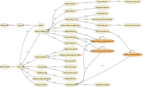
Fig. 2.Snapshot of the Ontology where the Robot and its components are defined .
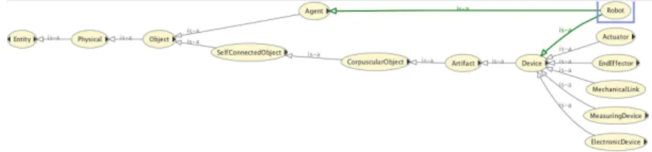
The Robot definition and its Main Parts are based on the IEEE standard [6], where the SUMO [8] upper ontology was used. In figure 1 the core definitions are presented directly in the standard, where is depicted that a robot is a device and also an agent that can reason, based on existing knowledge. Moreover, in figure 1, are also depicted several Objects, i.e., physical entities, that can be part of a robot, e.g., a measuring device, a mechanical link, etc.
Moving deeper in the ontology, and the knowledge representation of the robot components, figure 2 defines the large majority of them. The ComputerHardware class is defined in SUMO as an Artifact –Product, and not present in figure 2, although is needed for the robotic system to process some tasks, as will be shown in section 3. The classes defined and its properties like AttachedTo, hasPurpose, robotPart, robotSensingPart, EquippedWith, isSupportedBy are defined in the standard and will be used in section 5 to reason on the ontologies, and validate the proposed approach.
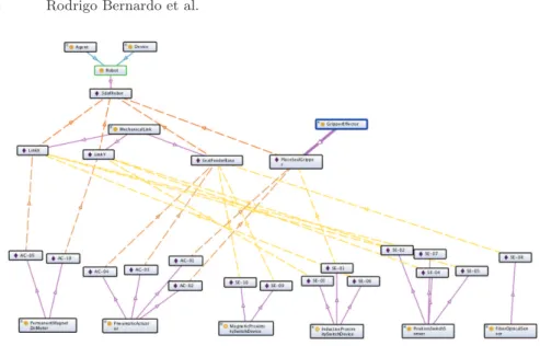
After the robotic system ontology is defined, it is necessary to instantiate all the components that exist in the system, i.e., define individuals based on its type. Amongst the various components that do exist in the system, figure 3 de-picts the 3 degrees of freedom robot manipulator, 3dofRobot. Other example, the
Fig. 3.The Ontology used to instantiate the robotics components used on the manip-ulator of the Robotic System.
ComputerHardwarewhere are implemented and running several ComputerTasks defined in section 3 is instantiated as a DellComputer.
From the Knowledge based built, all the components from the machine are instantiated. The main sensors and actuators are present in the knowledge model depicted in figure 3, where all the instances are present. Moreover, several infor-mation can be inferred from the diagram. The actuator(AC) AC-09 is attached to LinkX that is also attached to the 3dofRobot, being the latter an instance of the class Robot. Similar inferences can be drawn for the sensor, e.g., SE-08 is attached to the SealFeederBase. For the pneumatic actuators present in the gripper, the instances were named: AC-02 and AC-01, as depicted in figure 3. In the same figure the instance SE-01 is a sensor(SE) that is equivalent to the sensor classes: ProximitySensor, SwitchDevice, InductiveSensor. The Robot in-stance is named 3dofRobot and the GriperEfffector class has an inin-stance named PlaceSealGripper.
For the sensors and actuators, the instance names in the knowledge base are exactly the same that are present in the electric circuits, which is very useful for the maintenance of the Robotic System.
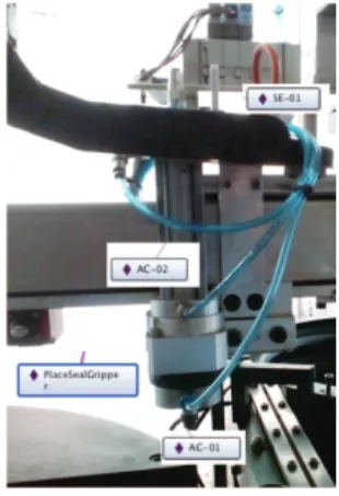
Figure 4, presents the physical components of the robotic system, i.e., a close up of the real PlaceSealGripper instance, along with the two pneumatic actuators and the sensor to detect the back and forward position of the Gripper.
As previously said in this section, having the robotic system represented in an ontological knowledge base is of special interest, for example to the maintenance division of the factory. In fact, as depicted in figure 5, the information about the sensor is completely available to the user and a simple Description Logic
Fig. 4.The real robot image of the PlaceSealGripper, an instance of the GripperEffector class.
Query to the ontology will retrieve useful information, for example where the component is attached. Section 5 will discuss this issue.
Fig. 5.Example of the knowledge representation of a Robotic System component that was instantiated.
3
Robot Processes, Tasks and Ontologies
This section presents the tasks that the robot must perform to achieve its goals. As presented in previous work from the authors [4] the robot must place sealants in a harness connecting box. The tasks needed are typically pick and place robotic tasks, where a pneumatic gripper was developed. The early proposed system [4] evolved and is now capable to perform quality control, using machine vision, for all the connecting boxes produced. Also, the robotic system is capable to correct errors that arrive of non-placed sealants, due to wrong picking, and from sealants not inserted in the holes.
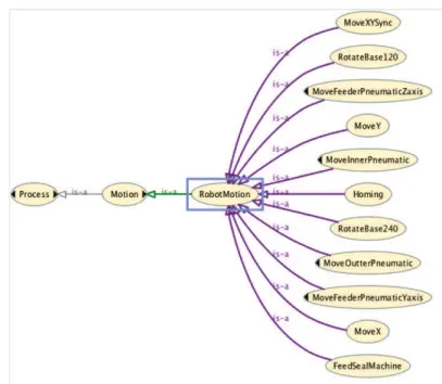
Using CORA and SUMO, the processes and tasks for the robot and vision systems were defined. Figure 6, presents the main processes and tasks, defined within the main class defined in CORA RobotMotion and in SUMO Motion and ComputerTask. These tasks are high level, defined in the ontology and have low
Fig. 6.The definition of Process and the main Tasks to be completed by the Robotic System.
level tasks therein, that are implemented in the ProgrammableLogicController and the ComputerHardware instances defined in the previous section.
The RobotMotion tasks defined, depicted in figure 7, are directly related to the actuators. The tasks ReleaseSeal and CaptureSeal, use pneumatic actu-ators, are inherited from the ComputerTask class, since are not direct robot movements and are dependent of other components of the machine. The tasks RotateBase120,RotateBase240 actuates a 3 phase electric motor to rotate the base where the connecting boxes are to be located in the environment, for sealant insertion. All the other tasks use the two DC motors of the robot joints to move the robot in the XY plane.
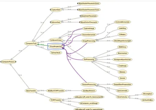
Fig. 8.The definition of the Computing Processes implemented in the Robotic System.
Having the robot tasks defined is important to define the tasks needed for the machine vision system, capable to inspect if the sealants where correctly inserted in the connecting boxes. Figure 8 depicts those tasks, along with the tasks needed to communicate between the machine vision system (implemented in a RaspBerryPI, an instance of a MicroController to CaptureImage) and the DellComputerwhere the machine vision algorithms run, using Matlab. These two components are connected using an ethernet connection, using a router, along with the ModiconLMC058 (the instance of the ProgrammableLogicController ).
The Machine Vision System performs VisualInspection, by performing the following tasks: CaptureImage, PreProcessing, ImageProcessing, FeatureExtrac-tion, FeatureProcessing. The system is calibrated by performing the task Cali-brateVision. For the tasks above, low level tasks were defined for this system, as depicted in figure 8. It is worth to be noted that ErrorCalculus tasks were defined and implemented for this system, that can evaluate if the goal is achieved or not, to be corrected by re-planning the tasks to be performed.
The work presented in this paper presented the basic tasks to be performed by the proposed robotics system, and aims in future works to align the current definitions with the work presented in [5] (The IEEE Robot Task Ontology Working Group), e.g., to have a formal definition to evaluate the task, for the robot behavior, and the constraints that the task may have.
4
Planning Using Ontologies
In this section is presented how the system can be re-planned by modifying the production orders arriving from the factory server, to correct the errors identified in the ErrorCalculus tasks.
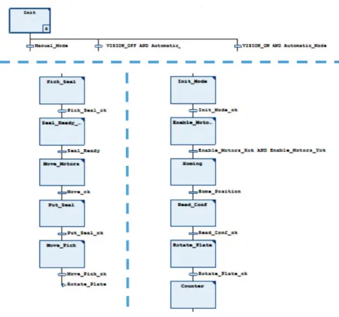
As depicted in figure 9 the operator and/or technician can have access to manually operate the robotic system (for testing sensors and actuators) and to start automatically production orders. This can be done with the Machine Vision system enabled or disabled. The sequence of picking and placing a Sealant is the same for all sealants (lower left part of figure 9) and the only variation is the position of the sealants, that arrives by reading the production order that is written in the ModiconLC058 by the ModBusTCPIPTranfer, SendSealPattern, arriving from the Factory Production Server and/or the Machine Vision System (in case of an error is detected in the ErrorCalculus task).
The re-planning of the system is done on-the-fly, when and image is captured in the VisionInspectionZone, as depicted in right side of the figure 10. If the ErrorCalculus tasks detects an error, the Vision System, sends a production order with the sealant position(s) that must be placed in the connecting box, in the ManipulationZone (depicted in the left part of figure 10 and behind the pillar in the right part of figure 10) of the environment. After this high priority task is finished and completed successfully, the robotic system resumes the production order.
5
Validation and Discussion
Using the ontology and description logic queries, is straight forward to obtain the following information:
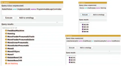
– Sensors and actuators on the end-effector of the robot, as depicted in the lower right part of figure 11.
– Robot Motion Tasks Implemented in the Programmable Logic Controller, as depicted in the left part of figure 11.
Fig. 9.The implementation of plans, sequence of tasks. Upper part: the initial operator choices. Lower left: the sequence of picking and placing a Sealant. Lower right: to setup the system and Read the sealants pattern, in Read-conf.
– Devices instantiated in the Ontology, which have the purpose of Homing the Robot, as depicted in upper right part of figure 11.
Fig. 11. Reasoning using the ontology. Left: query about the Robot Motion Tasks Implemented in the Programmable Logic Controller. Upper Right: query about the Devices instantiated in the Ontology, which have the purpose of Homing the Robot. Lower ight: query about the sensors and actuators on the end-effector.
Performing description logic reasoning actions to obtain valuable data for production and maintenance at the factory level, can be done as presented in figure 11, namely information about sensors, actuators, and its purpose in the tasks defined in the ontology. For example what is the type of Sensor instantiated with SE-01? in which tasks it is used? in which zone of the robotic system is it placed? and many other information requested by the factory level.
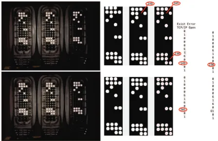
To validate the Machine Vision system and the re-planning tasks, in figure 12 the captured and segmented images are presented (with 3 sealants missing, one in the middle box and 2 other in the right box). The Machine vision system starts the ModBusTCPIPTransfer task and sendSealPattern sending the Mod-Bus string depicted in the right side of figure 12, with the positions of the 3 errors and a final statement saying that no more errors are present. The Sealant Placement Plan, depicted in figure 9, is automatically changed and the next step will be to Rotate240 and move the boxes to the ManipulationZone directly to place the sealants correctly.
6
Conclusions
The paper proposed an ontology driven framework to define a machine used for automatic pick and place robotic tasks, capable to evaluate the final goal to be
Fig. 12.Inspection results obtained from the Machine Vision System. Upper Images, with error in sealants placement. Lower Images, without errors. Middle Images, after processing. On the right the ModBus String with the re-planning of the order, i.e., the positions with missing sealants and the last string with code 61, stating the end of the order.
achieved. The developed framework was successfully simulated and validated in an automotive manufacturing environment where sealants have to be placed in a harness connecting box for the automotive industry. The developed framework was built based on the IEEE ORA standard and SUMO upper ontology. Specific contributions were developed to extend the previous ontologies to the presented application case, e.g., for interaction with environment and robot movement.
The system is capable to perform quality control, using machine vision, for all the connecting boxes produced. Also, the robotic system is capable to correct errors that arrive of non-placed sealants, due to wrong picking, and from artifacts presented in the connecting boxes.
Based on the tasks/processes obtained from the developed framework, the robotic system will place correctly a batch of sealant patterns, in an automatic way, while re-planning its behavior when an error occurs and or a new production order arrives from the Factory Production Server.
The proposed future work is to align the current tasks definitions with the work presented in [5], e.g., to have a formal definition to evaluate the task, for the robot behavior, and the constraints that the task may have.
Acknowledgments
This work was partly supported by Instituto Politecnico de Castelo Branco and by FCT, through IDMEC, under LAETA, project UID/EMS/50022/2013.
References
1. Siciliano, Bruno, Khatib, Oussama (Eds.): Springer Handbook of Robotics, 2nd edition, Springer International Publishing (2006). doi:10.1007/978-3-319-32552-1 2. Smith, N., ”Enhancing Automotive Wire Harness Manufacturing Through Digital
Continuity,” SAE Technical Paper 2015-01-0238 (2015). doi:10.4271/2015-01-0238 3. Edson Prestes, Joel Luis Carbonera, Sandro Rama Fiorini, Vitor A. M. Jorge, Mara
Abel, Raj Madhavan, Angela Locoro, Paulo Goncalves, Marcos E. Barreto, Maki Habib, Abdelghani Chibani, Sbastien Grard, Yacine Amirat, Craig Schlenoff: To-wards a core ontology for robotics and automation, Robotics and Autonomous Sys-tems, Volume 61, Issue 11, (2013). doi:10.1016/j.robot.2013.04.005
4. Farinha, R., Gon´calves, P.J.S. : Knowledge Based Robotic System, towards ontology driven pick and place taks, Romanian Review Precision Mechanics, Optics and Mechatronics 49 pp. 152157, (2016). doi:10.17683/rrpmom.issue.49
5. Stephen Balakirsky, Craig Schlenoff, Sandro Fiorini, Signe Redfield, Marcos Bar-reto, Hirenkumar Nakawala, Joel Luis Carbonera, Larisa Soldatova, Julita Bermejo-Alonso, and Fatima Maikore, Paulo J. S. Gonalves, Elena De Momi, Veera Ragavan, Tamas Haidegger: Towards a Robot Task Ontology Standard, In Proceedings of the 12th Manufacturing Science and Engineering Conference. Los Angeles, U.S.A. (2017).
6. IEEE Std. 1872-2015: IEEE Standard Ontologies for Robotics and Automation (2015). doi:10.1109/IEEESTD.2015.7084073
7. Joel Carbonera, Sandro Fiorini, Edson Prestes, Vitor A. M. Jorge, Mara Abel, Raj Madhavan, Angela Locoro, P.J.S. Gonalves, Tams Haidegger, Marcos E. Barreto, Craig Schlenoff: Defining Positioning in a Core Ontology for Robotics. In Proc. of IEEE/RSJ International Conference on Intelligent Robots and Systems (IROS). pp. 1867- 1872. Tokyo, Japan (2013). doi:10.1109/IROS.2013.6696603
8. Pease, Adam, Ian Niles, and John Li. ”The suggested upper merged ontology: A large ontology for the semantic web and its applications.” Working notes of the AAAI-2002 workshop on ontologies and the semantic web. Vol. 28. (2002).