Volume 2010, Article ID 727909,10pages doi:10.1155/2010/727909
Research Article
A Reconfigurable System Approach to the Direct
Kinematics of a 5
D.o.f
Robotic Manipulator
Diego F. S ´anchez, Daniel M. Mu˜
noz, Carlos H. Llanos, and Jos´e M. Motta
Departamento de Engenharia Mecˆanica, Universidade de Bras´ılia, 70910-900 Brasilia, DF, Brazil
Correspondence should be addressed to Carlos H. Llanos,[email protected]
Received 10 March 2010; Revised 19 October 2010; Accepted 17 December 2010
Academic Editor: Lionel Torres
Copyright © 2010 Diego F. S´anchez et al. This is an open access article distributed under the Creative Commons Attribution License, which permits unrestricted use, distribution, and reproduction in any medium, provided the original work is properly cited.
Hardware acceleration in high performance computer systems has a particular interest for many engineering and scientific applications in which a large number of arithmetic operations and transcendental functions must be computed. In this paper a hardware architecture for computing direct kinematics of robot manipulators with 5 degrees of freedom (5D.o.f) using floating-point arithmetic is presented for 32, 43, and 64 bit-width representations and it is implemented in Field Programmable Gate Arrays (FPGAs). The proposed architecture has been developed using several floating-point libraries for arithmetic and transcendental functions operators, allowing the designer to select (pre-synthesis) a suitable bit-width representation according to the accuracy and dynamic range, as well as the area, elapsed time and power consumption requirements of the application. Synthesis results demonstrate the effectiveness and high performance of the implemented cores on commercial FPGAs. Simulation results have been addressed in order to compute the Mean Square Error (MSE), using the Matlab as statistical estimator, validating the correct behavior of the implemented cores. Additionally, the processing time of the hardware architecture was compared with the same formulation implemented in software, using the PowerPC (FPGA embedded processor), demonstrating that the hardware architecture speeds-up by factor of 1298 the software implementation.
1. Introduction
Currently, there exists a real demand in many robotics applications for higher operational speeds, and the solutions improving performance would have clear benefits in terms of manufacturing efficiency, precision, and processing time. In general, a fully operational robotic system running in real-time requires the repeated execution of a variety of complex algorithms, which involve the use of several transcendental functions and arithmetic operations. Most of these algo-rithms, if not all, need to be computed within milliseconds (ms) or microseconds (µs) in order to keep several real-time constraints. Such algorithms require massive computing power that surpasses the capabilities of many sequential computers [1].
A classical but important problem in the robotic ma-nipulator is the direct kinematics. The direct kinematics allows the Cartesian location of the end effector to be calculated from measured values of the joint angles [2]. This
mathematical formulation frequently needs a large num-ber of arithmetic and trigonometric computations that must ideally be performed in a floating point, because of precision requirement [2]. Design and implementation of floating-point arithmetic operations in FPGAs has a relevant importance in a variety of scientific applications (such as robotics) due to the large dynamic range for representing real numbers, which permits suitable representation of both very small and large numbers in a fixed bit-width with proper precision. Additionally, the software implementations of direct kinematics computations are very expensive in processing time due to the sequential behavior of general purpose processors (GPPs).
the instruction memories. This problem, well known as von Neumann bottleneck, has been partially overcome by using multicores microprocessors reducing the execution time. Recently, Graphic Processor Units (GPUs) have been used for implementing complex algorithms taking advantage of the parallel floating-point units and increasing in this way their throughput in execution time. Although the GPU-based implementations achieves a noticeable speed-up, it is important to point out the following aspects: (a) the GPU-based solution presents bandwidth bottlenecks when all the source data are accessed from global memory or when simultaneous accesses from different threads to memory have to be addressed, (b) GPUs are not tailored for specific applications and commonly are difficult to fine-tune for executing only the operations required by an algorithm, and (c) these integrated circuits operate at high frequencies leading to large power consumption. This is a drawback for embedded system applications.
Due to the high capacity of parallel processing, FPGAs are now being used to accelerate processes such as digital signal processing, image processing, robotics, encryption and decryption, and communication protocol decoding [3,4]. Robot tasks with higher operational speeds are one of the applications that require high processing capabilities. Therefore, the FPGA implementation of direct kinematics can be an important solution in order to achieve several real-time constraints.
There are two important aspects that must be consid-ered when parallel processing computations using floating-point operators are implemented in FPGA: (a) the tradeoff between the need of reasonable accuracy and the cost of logic area and (b) the choice of a suitable format such that dynamic range is large enough to guarantee that saturation will not occur for a general-purpose application.
Current advances in VLSI technology raised the den-sity integration fast enough for allowing the designers to develop directly in hardware several algorithms commonly implemented on software, thus, obtaining an expressive processing speed-up [5]. Moreover, computation of direct kinematics has high parallelization capabilities, and then, the performance can be improved by implementing it on FPGAs. In this way, a hardware architecture of direct kinematics taking advantage of these features could be useful in robotics applications that require high-speed movements.
In this paper, an FPGA implementation for computing the direct kinematics of a spheric robot with five degrees of freedom (5 D.o.f) is described. The hardware architecture considers a floating-point arithmetic, parameterizable by bit-width, allowing the designer to choose a suitable format according to the available hardware resources, accuracy and dynamic range requirements. The main contributions of this work can be summarized as follows: (a) the proposed architecture makes use of several floating-point arithmetic and trigonometric libraries, allowing the performance to be improved in comparison with previous works imple-mentations, in which the floating-point operations are executed in software using DSPs, GPUs, or CPUs (see Section 2), (b) this work presents an error analysis for different bit-width representations (32, 43, and 64 bits),
allowing the designer to analyze the tradeoff between the bit-width representation, which directly affects the cost in logic area and the accuracy requirements. Comparison of the processing time between the hardware architecture and a software implementation, using a PowerPC embedded microprocessor, is also presented, (c) the proposed hardware architecture has been developed taking into account a resource constrained methodology, allowing the arithmetic and trigonometric units to be scheduled between different states in order to achieve the lowest execution time according to the available hardware resources.
Section 2presents the related works covering hardware implementations of direct and inverse kinematics. Section3 describes the direct kinematics mathematical formulation. Section4describes the IEEE-754 standard for the floating-point number representation and a tradeoff analysis of the FPGA implementation of the floating-point operators required by the direct kinematics. Section 5 presents the FPGA implementations and, before concluding, Section 6 presents the synthesis and simulation results.
2. Related Works
Several previous works have presented hardware architec-tures for implementing only the servo control loop of robotic manipulators, being in these cases the direct and inverse kinematics computed on software [6–9]. In [6,7] a hardware structure for controlling a SCARA robotic manipulator is developed, relieving the computational cost of general purpose microprocessor by implementing on FPGAs the servo control loop of the robot manipulator.
In [8,9] a hardware-software codesign for controlling an articulated robot arm is presented, using a NIOS processor for implementing the inverse kinematics. In the same context, in [10] the case study is a neural controller for 3
D.o.f parallel robot for milling. This controller is based on neural model of the inverse dynamics of the manipulator, trained on data collected with the use of a computed torque stabilizing controller, and the authors propose that good candidates for hardware implementation are those fragments of an algorithm that can be calculated using only fixed-point operations, due to the fact that they require less FPGA resources and, therefore, are faster whenever are compared with floating-point modules. The other parts of the algorithm (including those working with floating-point) are good candidates to be implemented in an embedded processor. Additionally, [11] proposes hardware solutions based on an ARM processor and fixed-point FPGA modules for computing the trigonometric and square root functions of inverse kinematics. They are based on existing pipeline arithmetic circuits, which employ the CORDIC (Coordinate Rotation Digital Computer) algorithm.
hardware peripherals (PWM controllers and interfaces for data communication), connected among them throughout a NIOS embedded processor. On the other hand, [13] shows the implementation of the direct kinematic and force feedback algorithm using both CORDIC (for fixed-point) and Xilinx arithmetic library. This work has measured the error of the direct kinematics with respect to a PC implementation, in which numerical analysis shows that Cartesian position error is always below 0.1 mm and the error in orientation is less than 0.001 deg. Although a 32 bit fixed-point data representation is used, details about the same (for example, bit number for fractional part) are not described.
In [14] a hardware implementation of inverse kinematics and a servo controller for a robot manipulator are proposed, allowing the FPGA to compute the high complex com-putations, such as the transcendental functions, as well as exploring the parallel capabilities of the inverse kinematics. As previous approaches, all hardware embedded operations are performed in fixed-point.
In [15] a generic controller for a multiple-axis motion system (that can be applied to a manipulator) is imple-mented, which includes several modules such as velocity profile generator, interpolation calculator, inverse kinematics calculator, PID controller, among others. In this case, the trigonometric operations (such as sin, cos, arc tang and arc cosine) have been also implemented by using lookup tables and a fixed-point arithmetic representation.
Additionally, [16] shows the direct and inverse kine-matics computation of a 6 D.o.f space manipulator using an ARM processor and FPGA coprocessor. Additionally, it considers the hardware implementation of a pipelined CORDIC library in an FPGA device (using fixed-point representation). The experiment shows that the absolute accuracy of the end-effector is less than 3 mm error. In [17] an optimized inverse kinematics approach is proposed for controlling an arm of a virtual human, in which an FPGA device is used for accelerating the computations. In order to improve the performance, a floating to fixed point conversion is performed; however, it imposes a limitation on the dynamic range of the operations.
In summary, almost all previous works describe a hardware-software codesign for implementing the direct and inverse kinematics, in which critical parts are developed in hardware accelerators, developed in FPGAs. On the other hand, these previous works do not consider explicitly floating-point arithmetic for performing the computations using appropriated arithmetic libraries for FPGA, and this can become very important as required by several engi-neering applications such as robotic manipulators, in which high accuracy and a large dynamic range are important requirements, apart from attending both good performance and low cost in logic area. In this context, taking the impor-tance and dramatical growth of embedded application for automation, control, and robotics areas [18], the full hard-ware implementation of a kinematics is very important to be researched, in terms of comparing the cost, performance and precision with respective software implementations, specially developed over FPGA embedded processors. Additionally, most of the previous works do not show the error analysis
comparing both hardware and software results of the same kinematics, and only few ones measure the error of the direct/inverse kinematics (for instance, [13,16]) using only fixed-point representation.
3. Background
3.1. Direct Kinematics. A robot manipulator can be described as a series of links, which connect the end effector to the base, with each link connected to the next by an actuated joint. Attaching a coordinate frame to each link, the relationship between two links can be described with a homogeneous transformation matrix—an A matrix. Therefore, a sequence of theseAmatrices relates the based to the hand of the manipulator (see (1)) [2].
RT
H= A1A2· · ·An−1An. (1)
Thus, the direct kinematics problem is summarized by finding a homogeneous matrix transformationTthat relates the end effector pose (position and orientation) to the based coordinate frame, knowing the angles and displacement between the links and the geometric parameters of the manipulator [2].
not intersect, then the frame origin is placed at the distal joint; subsequently, if a frame origin is described relative to another coordinate frame by using more than one direction, then it must be moved to make use of only one direction if possible. Thus, the frame origins will be described using the minimum number of link parameters. The x-axis or the y-axis have their direction according to the convention used to parameterize the transformations between links. At this point the homogeneous transformations between joints must have already been determined. The other axis (x or y) can be determined using the right-hand rule. A coordinate frame can be attached to the end of the final link, within the end-effector or tool, or it may be necessary to locate this coordinate frame at the tool plate and have a separate hand transformation. Thez-axis of the frame is in the same direction as the z-axis of the frame assigned to the last joint (n−1). The end-effector or tool frame location and orientation is defined according to the controller conventions. The homogeneous transformations between joints follow the Denavit-Hartemberg convention (D-H), making two consecutive links related through 4 basic transformations that only depend on the link geometry [2]. The transformations are:
(1) a rotation about thezn−1 axis by the angle between links (θn),
(2) a translation along the zn−1 axis of the distance between the links (dn),
(3) a translation along thexnaxis (rotatedxn−1axis) of the length of the link (ln),
(4) a rotation about thexnaxis of the twist angle (αn).
An=R(z,θn)T(0, 0,dn)T(ln, 0, 0)R(x,αn). (2)
θn, dn, ln, and αn represent the D-H parameters of the link n. Identifying these parameters, theAmatrix that relates two consecutive links can be obtained. Multiplying the sequence of theAmatrices (see (1)) a homogeneous matrix transformationT is obtained, solving the direct kinematics problem.
3.2. Direct kinematics for a Spherical Robot Manipulator.
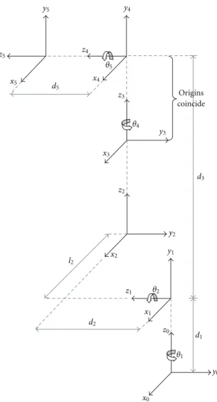
The robot described in this paper has a spherical topology with 5 degrees of freedom, with two rotational joints in the base followed by a prismatic joint and two rotational joints located in manipulator hand. The first three joints are responsible for the wrist position and the two last ones are responsible for the hand or tool orientation. Figure1shows the proposed robot topology.
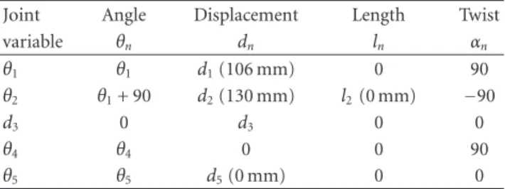
Figure2shows the assigned coordinate frame to each link following the convention D-H for the manipulator depicted in Figure1. Table1presents the D-H parameters.
Table1can be used for computing the matrix that relates two consecutive axis frames of the robot, and finally, by multiplying the sequence of theAmatrices, a homogeneous matrix transformationT is obtained. The matrixT can be formulated as shown in Equation (3), where the entries
θ1
θ2 θ4
θ5
d3
Figure1: Five degrees of freedom Robot Manipulator.
θ1 l2
x0 x1 x2 x3 x4 x5
y0 y1
y2 y3 y4
y5
z0 z1
z2 z3 z4
z5
θ2
d2
d1 d3 θ4
d5
θ5
Origins coincide
1 Ew Mw
±
M
S E
Mantissa=1·M
E+ bias
Figure3: IEEE-754 format.
Table1: Denavit-Hartenberg parameter of robot manipulator.
Joint Angle Displacement Length Twist
variable θn dn ln αn
θ1 θ1 d1(106 mm) 0 90
θ2 θ1+ 90 d2(130 mm) l2(0 mm) −90
d3 0 d3 0 0
θ4 θ4 0 0 90
θ5 θ5 d5(0 mm) 0 0
of T follow a notation that represents, for example, yx as the projection of the yaxis of the last coordinate frame in thexaxis of the base frame, andpxis thexcomponent of the origin coordinates of the last frame represented in the base frame.
T=
xx yx zx px
xy yy zy py
xz yz zz pz
0 0 0 1
. (3)
By using the D-H notation, the matrixTis summarized by the (4) to (15). In these equations the notation Ci = cos(θi) andSi=sin(θi) was used.
xx=(−C1S2C4−S1S4)C5−C1C2S5, (4)
xy=(−S1S2C4+C1S4)C5−S1S2S5, (5)
xz=C2C4C5−S2S5, (6)
yx= −(−C1S2C4−S1S4)S5−C1C2C5, (7)
yy= −(−S1S2C4+C1S4)S5−S1C2C5, (8)
yz = −C2C4S5−S2C5, (9)
zx= −C1S2S4+S1C4, (10)
zy= −S1S2S4−C1C4, (11)
zz=C2S4, (12)
px= −C1C2d3−C1S2l2+S1d2, (13)
py= −S1C2d3−S1S2l2−C1d2, (14)
pz = −S2d3+l2C2+d1. (15)
It can be observed in the (4) to (15) that some intermediate computations are found in two equations. For example, the intermediate computation (C1C2C4 − C1S2S4) is presented in the (4) and (7). In this way, the intermediate computation should be computed only once, saving processing time.
Although parameter l2 is equal to zero, it will be taken into account for future calibration purposes.
4. Description and Analysis of
the Floating-Point Operators
4.1. IEEE-754 Format. The IEEE-754 format [20] is a floating-point number representation characterized by three components: a signS, a biased exponentEwithEwbit-width and a mantissaMwithMw bit-width as shown in Figure3. A zero sign bit denotes a positive number and a one sign bit denotes a negative number. A constant (bias) is added to the exponent in order to make the exponent’s range nonnegative and the mantissa represents the magnitude of the number. The standard also includes extensive recommendations for advanced exception handling, additional operations (such as trigonometric functions), and expression evaluation for achieving reproducible results.
This standard allows the user to work not only with the 32-bit single precision and 64-bit double precision, but also with a suitable precision according to the application. This is suitable for supporting variable precision floating-point operations [21].
4.2. An Architectural Approach for Floating-Point Operators.
As stated in (4) to (15), the direct kinematics computation of the spherical robot described above requires the computation of add/sub and multiplication arithmetic operators, as well as the sine and cosine transcendental functions. Previous works covering hardware implementations of floating-point transcendental functions on FPGAs are based on CORDIC algorithms using simple and double precision formats [22– 24]. In [25] a HOTBM method for computing trigonometric functions in FPGAs is presented, achieving a reduced area and high performance without sacrificing accuracy. However, these works have not received enough attention on the cost in area associated with the precision level, as well as, their respective error analysis.
(see Section 4); therefore, the choice of using a Tay-lor expansion approach for computing the floating-point trigonometric operators can be justified. This work considers accuracy as a design criterion and provides an error analysis associated to the bit-width representation and the area cost, as well as, an error analysis associated to the number of iterations of the Taylor series. These results are useful for choosing a suitable format for representing real numbers according to general-purpose applications.
The Taylor series of sine, cosine and arctangent functions, around 0 are given, respectively, as
sin(x)=x−x 3
3! + x5 5! −
x7
7! +· · ·, (16)
cos(x)=1−x 2
2! + x4 4! −
x6
6! +· · ·, (17)
arctan(x)=x−x 3
3 + x5
5 − x7
7 +· · ·. (18)
The factors 1/n! and 1/n are precomputed and stored in a ROM avoiding additional operations. Before the first iteration, the x2 term is computed and stored. In each iteration one floating-point addition of the accumulated approximation with theith term is necessary. Additionally, for computing the ith term two floating-point multipli-cations are needed: (1) for computing either x2x2i−1 or x2x2(i−1)for sine/arctangent or cosine, respectively, and (2) for computing either 1/(2i+ 1)!x2i+1for sine, 1/(2i+ 1)x2i+1 for arctangent and 1/(2i)!x2ifor cosine.
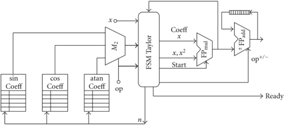
Figure4shows the proposed architecture for the Taylor series expansion. This approach was achieved using only one FPmultiplier, an FPadd/sub, a Finite State Machine (FSM), and three ROMs for storing the precomputed 1/n! and 1/n factors. The op signal chooses between a sin, cos or atan functions. The FSM synchronizes the FPmultiplier, FPadd/sub units and alternates the op+/− signal. At the first iteration, the factor x2 is computed and stored in a register and fed back to the FSM. Afterward, the precomputed coefficients are selected in order to compute the current term either x2n−1/(2n − 1)! for sine, x2n−1/(2n − 1) for arctangent or x2n/2n! for cosine. The add/sub unit computes and accumulates both the addition or subtraction operations. AfterNiterations, the ready signal indicates a valid output.
Table2 shows the Mean Square Error (MSE) results of the arithmetic and transcendental functions architectures for different bit-width representations (24, 32, 43, and 64 bits), using the Matlab results as statistical estimators. The Taylor architecture uses 5 nonzero powers (5 terms of the series expansion). As expected, the best results were achieved using the double precision format (64 bits); however, one can expect a large cost in logic area.
Table3presents the MSE and latency in clock cycles for the Taylor series expansion, using a simple precision format (32 bits). It can be observed that the smaller error achieved by the FPTaylorcore is overE−15, for five powers (x11polynomial degree). With more than five powers in the series expansion, the error due to the Runge’s phenomenon is increased [29]
Table2: MSE of the floating-point operators.
FP-Core 24(6, 17) 32(8, 23) 43(11, 31) 64(11, 52) Add/sub 2.27E−7 2.76E−11 3.24E−15 1.26E−17
Multiplier 9.53E−4 1.53E−7 1.49E−11 5.87E−16
Taylor sin/cos 6.31E−9 8.80E−9 6.26E−9 1.94E−16
Taylor atan 0.073 0.0014 0.015 0.015
Table3: MSE and Latency of theFPTaylorarchitecture.
Powers sin(x) cos(x) atan(x) Elapsed time [−π/2π/2] [−π/2π/2] [−100 100] clock cycles
2 1.59E−03 3, 52E−02 0.00137 11
3 1.56E−06 5, 58E−05 0.00136 15
4 7.01E−13 3.62E−11 0.00136 19
5 3.13E−15 1.15E−14 0.00136 23
6 2.13E−14 5.91E−15 0.00136 27
Table4: Synthesis results. Virtex2 XC2VP30.
Bit-width Slices LUTs Mult18×18 Freq
(Exp, Man) (13696) (27392) (136) (MHz)
32(8, 23) 10528 20017 48 54.83
43(11, 31) 14589 27807 48 48.31
64(11, 52) 34031 64687 180 39.51
Table5: Synthesis results. Virtex5 XC5VLX110T.
Bit-width Slices LUTs DSP48Es Freq
(Exp, Man) (69120) (69120) (64) (MHz)
32(8, 23) 4051 14457 24 83.61
43(11, 31) 5349 19262 48 66.22
64(11, 52) 7901 98755 111 63.93
when using polynomial interpolation with polynomials of high degree.
5. The FPGA Implementations
FSM
T
ay
lor
FP
mu
l
x x
n
Start
Ready sin
Coeff
cos Coeff
atan Coeff
x,x2
op M2
Coeff
±FP
add
op+/−
Figure4: IEEE-754 format.
a predefined restriction in execution time. Anyway, this kind of algorithms does not guarantee an optimal solution [30].
The control of the overall architecture was achieved by a Finite State Machine (FSM), and the overall architecture was described in VHDL using the Xilinx ISE 10.1 development tool, making use of the floating-point arithmetic units. Eight cores for computing transcendental functions were required: four for computing the sin function and the other four for computation the cos function. The necessary addition and subtraction operations were achieved by applying the FPadd/sub and FPmultiplier cores presented in [28] (see Sec-tion3). For computing the sin and cos functions, a Taylor series expansion was implemented, using a FPadd/sub and a FPmultipliercores, with a similar architecture to the presented in [26]. The FPTaylorcos and FPTaylorsin were achieved using 10 and 11 nonzero powers for cosine and sine respectively and an elapsed time of 23 clock cycles for cosine and 26 for sine.
It can be noticed that the orientation and position results are calculated from the following steps: in step 3 thexz and
yz, in step 4 the parameterpz, in step 5 thezzandpx, in step 6 thepy parameter is computed, in step 7 thezxandzy, in step 10 thexxandyx, and finally in step 11 thexyandyy(see Figure5).
In order to compare the performance of the proposed architecture, the direct kinematics was also implemented in software using a C code language running on an FPGA embedded PowerPC processor, using the Xilinx Platform Studio development tool. This approach allows the designer for having a just comparison between both hardware and software developments, which are running in the same environment (namely, the same FPGA with the same clock). To do that, two hardware peripherals were added to the PLB bus of the PowerPC processor: the first one for counting the clock cycles and the second one for accomplishing a RS-232 serial communication to a Matlab environment. The counter is used for measuring the processing time in software by means of enable and stop ports (both addressed by the PLB bus), which are controlled by specific software instructions. Figure 6 shows the connection between the PowerPC processor and the hardware peripherals.
6. Results
6.1. Synthesis Results. Synthesis results are shown in Table4 for the Xilinx Virtex2 family (chip xc2vp30) using the ISE 10.1 development tool. It can be observed that the cost and performance of the architecture are presented in Figure 5 for different bit-width (exponent and mantissa), including both the simple precision and double precision (IEEE-754 standard). As expected, large bit-width representations are more expensive in terms of area if compared with small bit-width representations. Additionally, the performance is better when using small bit-widths.
It can be seen that the 43 and 64 bit-widths repre-sentations exceeded the hardware resources available in the specific Virtex2 FPGA (see Table4). However, it is important to take into account that the xc2vp30 is not the largest device of the Xilinx Virtex2 FPGA family. Modern FPGAs devices have a large number of configurable logic blocks (CLB), dedicated DSP blocks, among other facilities which are suitable for mapping complex algorithms directly in hardware. Table5 shows the cost in logic area of the same architecture using a Virtex5 FPGA (chip xc5vlx110t). It is important to take into account that the Virtex5 FPGA family uses embedded DSP48Es blocks, which considers 18×25 bits multipliers. It can be observed that the operational frequency has been increased; however the double precision represen-tations exceed the available number of LUTs. However, as will be explained below, simulation results point out that the single precision format (32 bits) achieves similar error results to large bit-width representations. Therefore, one can conclude that the 32 bit implementation is suitable in terms of hardware resources consumption and error associated for computing the direct kinematics of a 5D.o.f spheric robot.
8 In tern ation al Jo urn al o f R ec on fi gurable C o m putin cos cos cos cos sin sin sin sin θ1 θ4 θ5 θ2 θ1 θ4 θ5 θ2 C1 C1 C1 C1 C1 C2 C4 S1 S1 S1 S1 S1 S1 S1 S4 S4 S4 S4 S4 C5 C5 C1 C1 C4 C4 C4 C5 C5 C5 C5 S5 S5 S5 S5 S5 d3 d3 d3 S2 S2 S2 S2 d2 d1
S2C4
S2C4
S2C4 S1 C2 C2 C2 S1 C2 −+ −+ + + − + −+ −+ − − − − − − − − px pz py + + + + X X X X X X X X X X X X X X X X X X X X X X X X X X X X X X X l2 l2 MultA MultB MultC MultD MultA MultB MultC MultC MultD MultA MultB MultC MultD MultD MultD X X MultC MultD MultD MultA MultA MultA MultA MultB MultB MultB MultC MultB MultC MultD MultA MultB MultC xx xz xy zx zz zy MultC6 − + − +
S1C2 S1C2
X
X MultA
MultB
yx
Step 0 Step 1 Step 2 Step 3 Step 4 Step 5 Step 6 Step 7 Step 8 Step 9 Step 10 Step 11 C1C2
C1C2 C1C2
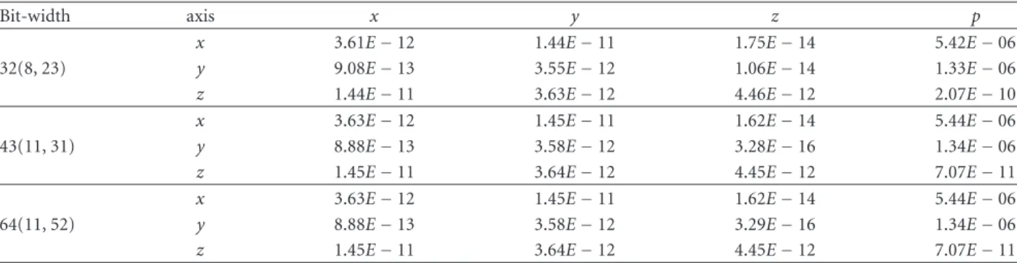
Table6: MSE for different bit-width representation.
Bit-width axis x y z p
x 3.61E−12 1.44E−11 1.75E−14 5.42E−06
32(8, 23) y 9.08E−13 3.55E−12 1.06E−14 1.33E−06
z 1.44E−11 3.63E−12 4.46E−12 2.07E−10
x 3.63E−12 1.45E−11 1.62E−14 5.44E−06
43(11, 31) y 8.88E−13 3.58E−12 3.28E−16 1.34E−06
z 1.45E−11 3.64E−12 4.45E−12 7.07E−11 x 3.63E−12 1.45E−11 1.62E−14 5.44E−06
64(11, 52) y 8.88E−13 3.58E−12 3.29E−16 1.34E−06
z 1.45E−11 3.64E−12 4.45E−12 7.07E−11
PLB RS232
Clk-cycles counter
Processor ppc-405 Rx
Tx
Clk
Uart
FPGA
Figure6: FPGA Architecture for Software Implementation.
Table7: Latency for each variable.
Stage Variable Latency
3 xz,yz 43
4 pz 46
5 zz,px 49
6 py 52
7 zx,zy 55
10 xx,yx 64
11 xy,yy 67
architecture, for which the set of Matlab results in double precision arithmetic were used as a statistical estimator.
For computing the MSE of the hardware architecture, 100 input values were used. The input ranges were−90◦to 90◦ for the anglesθ1,θ4, andθ5,−35◦to 20◦for the angleθ2, and 160 mm to 760 mm for theD3parameter.
Table 6 shows the MSE for different bit-width repre-sentations. Notice that the magnitude order of MSE does not have significant changes. Simulations using a bit-width representation smaller than a 32 bit-width representation did not present satisfactory results, due to saturation in the floating-point operators.
The software implementation (see Figure 6) was vali-dated using a simulation environment developed in Matlab and the serial RS232 interface for sending the input values and receiving the output values (position, orientation, and time processing in clock cycles). The aim of this simulation is to compare the processing time of the direct kinematics between software and hardware approaches and not to compare the error in the computations.
The elapsed time using the hardware architecture for each variable and each step is shown in Table 7. The overall direct kinematics is computed in 67 clock cycles. According to synthesis results, the maximum operational frequency is around 54 MHz for a single precision format, thus, all the computations are performed in 1.24µs. The software implementation has a processing time of 1.61036 ms for all computations of the direct kinematics in floating-point using a single precision. For comparison purposes we have only used the obtained operational frequency on the VirtexII FPGA family (54 MHz) due to the fact that this device has a PowerPC embedded processor. It can be observed that the hardware architecture is over 1298 times faster than the software implementation, which means a considerable speed-up in the processing time of the direct kinematics. These elapsed time results can be dependent on the operation scheduling used in the architecture.
7. Conclusion
An FPGA implementation of the direct kinematics of a spherical robot manipulator using floating-point units was presented. The proposed architecture was designed using a Time-Constrained Scheduling, using 8 cores for computing transcendental functions (sine and cosine), and sharing 4 multiplier floating-point cores and 2 addition/subtraction floating-point cores for computing the arithmetical oper-ations. Synthesis results show that the proposed hardware architecture for direct kinematics of robots is feasible in modern FPGAs families, in which there are plenty of logic elements available.
The overall computations were successfully performed and were validated using the Matlab results as a statistical estimator. The computation time to implement the direct kinematics in hardware is over 1.24µs, whereas the same formulation implemented in software using a PowerPC processor needs 1.61 ms, obtaining a considerable speed-up in the processing time.
comparison of the proposed hardware architecture with a multicore embedded processor approach.
References
[1] A. Y. Zomaya, “Parallel processing for robot dynamics compu-tations,”Parallel Computing, vol. 21, no. 4, pp. 649–668, 1995. [2] P. McKerrow,Introduction to Robotics, Adison-Wesley, New
York, NY, USA, 1991.
[3] S. Kilts,Advanced FPGA Design, John Wiley & Sons, Hoboken, NJ, USA, 2007.
[4] U. Meyer-Baese, Digital Signal Processing with Field Pro-grammable Gate Arrays, Springer, Berlin, Germany, 2001. [5] R. Andraka, “Survey of CORDIC algorithms for FPGA
based computers,” in Proceedings of the ACM/SIGDA 6th International Symposium on Field Programmable Gate Arrays (FPGA ’98), pp. 191–200, February 1998.
[6] X. Shao, S. Dong, and J. K. Mills, “A new motion control hardware architecture with FPGA-based IC design for robotic manipulators,” inProceedings of the IEEE International Confer-ence on Robotics and Automation (ICRA ’06), pp. 3520–3525, May 2006.
[7] X. Shao, D. Sun, and J. K. Mills, “Development of an FPGA-basedmotion control ASIC for robotic manipulators,” in
Proceedings of the IEEE International Intelligent Control and Automation, pp. 8221–8225, 2006.
[8] Y. S. Kung and G. S. Shu, “Development of a FPGA-based motion control IC for robot arm,” inProceedings of the IEEE International Conference on Industrial Technology (ICIT ’05), pp. 1397–1402, December 2005.
[9] Y. S. Kung and G. S. Shu, “Design and implementation of a control IC for vertical articulated robot arm using SOPC technology,” in Proceedings of the IEEE International Conference on Mechatronics (ICM ’05), pp. 532–536, July 2005. [10] M. Petko and G. Karpiel, “Hardware/software co-design of control algorithms,” inProceedings of the IEEE International Conference on Mechatronics and Automation (ICMA ’06), pp. 2156–2161, June 2006.
[11] R. Wei, M. Jin, J. J. Xia, Z. Xie, and H. Liu, “Reconfigurable parallel VLSI co-processor for spacerobots using FPGA,” in
Proceedings of the International Conference on Robotics and Biomimetics (ROBIO ’06), pp. 374–379, 2006.
[12] R. Wei, X. Gao, M. Jin et al., “An FPGA based hardware archi-tecture for HIT/DLR hand,” inProceedings of the International Conference on Intelligent Robots and Systems, pp. 523–528, 2005.
[13] S. Galvan, D. Botturi, and P. Fiorini, “FPGA-based controller for haptic devices,” inProceedings of the IEEE/RSJ International Conference on Intelligent Robots and Systems (IROS ’06), pp. 971–976, October 2006.
[14] Y.-S. Kung, K.-H. Tseng, C.-S. Chen, H.-Z. Sze, and A-P. Wang, “FPGA-implementation of inverse kinematics and servo controller for robot manipulator,” inProceedings of the IEEE International Conference on Robotics and Biomimetics (ROBIO ’06), pp. 1163–1168, 2006.
[15] J. U. Cho, Q. N. Le, and J. W. Jeon, “An FPGA-based multiple-axis motion control chip,” IEEE Transactions on Industrial Electronics, vol. 56, no. 3, pp. 856–870, 2009.
[16] Z. Yili, S. Hanxu, J. Qingxuan, and S. Guozhen, “Kinematics control for a 6-DOF space manipulator based on ARM Processor and FPGA Co-Processor,” inProceedings of the Inter-national Conference on Industrial Informatics (INDIN ’08), pp. 129–134, 2008.
[17] D. Hildenbrand, H. Lange, F. Stock, and A. Koch, “Efficient inverse kinematics algorithm based on conformal geometric algebra—using reconfigurable hardware,” inProceedings of the 3rd International Conference on Computer Graphics Theory and Applications (GRAPP ’08), pp. 1–8, Springer, 2008.
[18] R. Hartenstein, “Why we need reconfigurable computing edu-cation,” inProceedings of the IEEE Workshop on Reconfigurable Computing Education, pp. 1–4, 2006.
[19] R. P. Paul,Robot Manipulators—Mathematics, Programming, and Control, MIT Press, Boston, Mass, USA, 1981.
[20] “IEEE standard for binary floating-point arithmetic,” ANSI/IEEE Std 754-1985, August 1985.
[21] X. Wang,Variable precision floating-point divide and square root for efficient FPGA implementation of image and signal pro-cessing algorithms, Ph.D. dissertation, Northeastern University, 2007.
[22] J. Zhou, Y. Dong, Y. Dou, and Y. Lei, “Dynamic configurable floating-point FFT pipelines and hybrid-mode CORDIC on FPGA,” in Proceedings of The International Conference on Embedded Software and Systems (ICESS ’08), pp. 616–620, 2008.
[23] J. Valls, M. Kuhlmann, and K. K. Parhi, “Evaluation of CORDIC algorithms for FPGA design,”Journal of VLSI Signal Processing, vol. 32, no. 3, pp. 207–222, 2002.
[24] F. E. Ortiz, J. R. Humphrey, J. P. Durbano, and D. W. Prather, “A study on the design of floating-point functions in FPGAs,”
Field Programmable Logic and Applications, vol. 2778, pp. 1131–1135, 2003.
[25] J. Detrey and F. De Dinechin, “Floating-point trigonometric functions for FPGAs,” in Proceedings of the International Conference on Field Programmable Logic and Applications (FPL ’07), pp. 29–34, August 2007.
[26] D. M. Mu˜noz, D. F. Sanchez, C. H. Llanos, and M. Ayala-Rinc ´on, “Tradeoff of FPGA design of floating-point tran-scendental functions,” inProceedings of the IEEE International Conference on Very Large Scale Integration, pp. 1–4, 2009. [27] D. M. Mu˜noz, D. F. Sanchez, C. H. Llanos, and M.
Ayala-Rinc ´on, “FPGA based floating-point library for CORDIC algorithms,” inProceedings of the 6th Southern Programmable Logic Conference (SPL ’10), pp. 55–60, March 2010.
[28] D. F. S´anchez, D. M. Mu˜noz, C. H. Llanos, and M. Ayala-Rinc ´on, “Parameterizable floating-point library for arithmetic operations in FPGAs,” inProceedings of the 22nd ACM Sym-posium on Integrated Circuits and Systems Design (SBCCI ’09), pp. 253–254, 2009.
[29] C. Runge, “ber empirische funktionen und die interpolation zwischen quidistanten ordinaten,”Zeitschrift f¨ur Mathematik und Physik, vol. 46, pp. 224–243, 1901.