Improved Cell Coverage in Hilly Areas using
Cellular Antennas
Mridul Mohan Bharadwaj
Department of Computer Science& Engineering, Manipal University Jaipur, Jaipur Email:[email protected]
Jyotirmoy Karjee
Department of Computer Science & Engineering, Manipal University Jaipur, Jaipur Email :[email protected]
---ABSTRACT---This paper proposes an improved configuration of Cellular Antennas for terrains like hills where network coverage is poor and a number of black spots are very high. The proposed solution delivers efficient and much robust antenna structure which provides better network coverage by using 90-degree sector antennas. The radio spectrum of the 90-degree sector antenna is also shown to give the idea of cell coverage in order to build aseamless network in the region.This paper also proposes different channel allocation schemes that can be used with the proposed antenna configuration to deliver better network coverage and low call dropping probability. This is achieved by analyzing the terrain of the region and also the cellular traffic in the region. In areas where network traffic is almost constant or have low population, strategies like fixed channel allocation can be used effectively and efficiently. While in the areas where traffic is unpredictable or is subject to regional festivals or tourism, channel strategies like dynamic channel allocation are very useful to fulfill the demand of the overall network. The simulations and validations for the proposed methodology are done using MATLAB.
Keywords: Antenna Configuration, Cellular Network, Channel Allocation Schemes, Coverage Black Spots, Hill, S Sector Antenna, Terrain
--- --- Date of Submission: May 15, 2016 Date of Acceptance: May 30, 2016 --- ---
I.
INTRODUCTION
T
echnologicaladvancements and recent development in wireless and mobile devices were huge in the last decade. These developments have facilitated the growth of Wireless Communications and Mobile Computing. There are numerous applications of Wireless Mobile Networks which includes communications, entertainment, military, etc.On analyzing the recent trend in the growth of Mobile devices, it is expected to grow even more in the future. This results in limited bandwidth requirements for servicing all the users on the network. Thus leading the industry to develop more efficient network model. To provide efficient network model, more focus is needed towards Antenna Configurations of the Base Station and the Channel Allocation Strategies that are used to allocate channels in a given cell.[1] [2]In every cellular system, thewhole geographical area is divided into regularly shaped cells, which can either be hexagonal, square, circular or some other regular shapes. Out of these, hexagonal cells are widely used everywhere. Every cell has a base station (BS) located at the center of the cell. Mobile stations (MS) in each cell are serviced by the base station of the cell. Every base station is interconnected via underlying wired network which is also known as Backbone network. Base stations are also known as Mobile Service Station (MSS). Every wired network, many base stations are connected to a mobile switching
center (MSC). Cellular Networks are connected to the Internet through MSCs.
follows: Fixed Channel Allocation, Dynamic Channel Allocation, Hybrid Channel Allocation.
(A). Fixed Channel Allocation:
Fixed Channel Allocation Strategy (FCA) allocates a set of channels to each cell for use. These channels assigned are static and cannot be changed at any time. Channels are allocated in such a way that the channel reuse constraint can never be violated even if all the channels of all cells are used simultaneously. FCA is easy to implement but it is not adaptive to changing traffic conditions. If all the channels are occupied then no new call is served, even if, the neighboring base stations have free channels. FCA maximizes frequency reuse by allocating channels under minimum reuse distance constraint. In Basic Fixed Channel Allocation, a new call can only be served if there are channels free in the predetermined set, otherwise call will be blocked. In Simple Channel Borrowing Scheme, when all the available channels in a given cell are used, an available channel from the neighboring cell can be borrowed provided it does not interfere with the existing channel set. In Borrowing with Channel Ordering Scheme, all nominal channels are ordered such that the first
channel has thehighest priority of being assigned to next local call and the last channel has given highest priority of being borrowed by the neighboring cell. FCA is inefficient when traffic varies in every cell.[4]
(B) Dynamic Channel Allocation
In Dynamic Channel Allocation (DCA), there is no fixed relationship between channels and cells. All free channels are kept in a central pool, channels are allocated dynamically when a new call arrives and is returned to the pool after the call is completed. In DCA, voice channels are not permanently allocatedinstead, they are requested by the base station to the MSC. The evaluation of the cost for using a channel from thedifferent base station and to select the one with minimum cost must be provided while keeping the channel interference constraint satisfied. Selecting a candidate channel depends onthe future blocking probability in the vicinity of the cell, the reuse distance and the current traffic conditions. DCA scheme can be centralized or distributed. In Centralized DCA, a single controller is involved for selecting a channel for each cell. While in distributed DCA, a number of controllers are involved across the network (MSCs). DCA is highly complex and is less efficient as it involves real-time computation for allocating channels [5] [6].
(C) Hybrid Channel Allocation
Hybrid Channel Allocation (HCA) is a combination of fixed and dynamic channel allocation schemes where channels are divided into fixed and dynamic sets. Every cell is assigned a fixed number of cells as in the FCA scheme. When all the channels in a cell are used up, a request for a channel is initiated from the dynamic set. The channels in the dynamic set are shared by all users in the system to increase the flexibility. When a call arrives in a cell and all of its allocated channels are busy, then a channel is assigned from the dynamic set to service the
call. The procedure for assigning the channel to the user of thedifferent cell can be any of the DCA strategies.
II.
MOTIVATION
Although most of the technological advancements in the field of Channel Allocation Strategies are more prominent nowadays, but there are areas where these advancements fail to show their presence. Terrains like Hills are those areas where network coverage is very scarce and channel allocation strategies become a thing of future. That’s why it is equally important to review the Antenna Configuration of the underlying network. There are two types of antenna used in Cellular Systems namely, Omni-directional Antenna and Sector Antenna.
Omni-directional Antennas provides equal coverage in all directions. These antennas provide a horizontal radiation pattern of 360-degree. These antennas are used when network coverage is required in all the directions (horizontally). An Omni-directional antenna has a spherical coverage pattern ideal cases but generally the coverage is less in thevertical direction and more in thehorizontal direction. As theomnidirectional antennas radiate the energy in all the directions, less area is covered by theomnidirectional antenna.
III.
PROPOSED
WORK
In this section, a scheme is proposed to ensure seamless coverage in terrains such as Hills so as to minimize the number of black spots in the region. To do this, we propose to use Sector Antenna as Base Station (BS) in a cell. For this scheme, four 90-degree antenna model used to cover all the areas of the region. The main idea is to divide the region into hexagonal cells in which the sector antenna will be installed. As viewed from the top of the hill, it looks like a cone-shaped structure. Before designing the cell configuration, it is important to design the antenna to be used in the proposed model. The Table I, lists some of the parameters that we have used for the simulation:
Table I. Default Parameter values used for simulation
1 Frequency Range 2.4-2.5 GHz
2 Gain 15.0-17.0 dBi
3 Horizontal Beamwidth 91° 4 Vertical Beamwidth 90°
5 Max. Input Power 100 Watts
6 Max. Output Power 200 Watts
To calculate the Reference Gain GRef,
GRef =�4���
�
2 (1)
where GRX is the gain of the user antenna and λ is the
wavelength.Taking frequency f = 2.3 GHz, calculating wavelength λ:
λ = �
� = 0.1304 m (2)
where c is the speed of light.To calculate GRX, we use
the equation:
G = 10 log10 (GRX) = 31.62277 (3)
Using the result from Equation (3), we find out the value of GRef:
GRef = 3.405 × 10⁻³ (4)
GRef, dB = 10 log10 (GRef) = -24.67 dB (5)
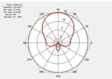
According to the proposed work, Figure 2 depicts the radiation pattern of 90-degree sector antenna used in a hexagonal cell in the hilly region. This coverage is based on one sector antenna. Therefore, by using four 90-degree sector antennas, most of the area in the cell is covered. The directivity of a sector antenna is a very important property. It is important while choosing the antenna for a specific application. If the need is to transmit or receive energy from a wider variety of applications, anantenna with low directivity should be used. Similarly, if power is transmitted to a specific region, anantenna with high directivity should be used. Fig 3 shows the directivity of the 90-degree sector antenna [8].
Fig. 3 Directivity of 90-degree Sector Antenna
Fig. 4. Hexagonal Cell Layout for Hilly Terrain
The proposed model as shown in Figure. 4, depicts the hexagonal structure which can be used to provide coverage in all the areas. The reason for not using regular hexagonal structure or “beehive” structure is that the it is not possible to allocate cells in the hilly terrain according to the regular hexagonal structure. So, to accommodate the change, the revised hexagonal structure as shown in Figure. 4 is used in the model. The area that is left-over by the four sector antennas in a cell is actually covered by the neighboring cell antennas. Hence, there are fewer chances for the presence of any black spot regions.The high terrain areas like hill have two types of regions. One is where a human population exists like city or villages. And the other is where there are only roads connecting different towns. So, on the basis of this, different channel strategies can be used. For areas like small towns situated on hill stations, Dynamic Channel Allocation Strategy is better suitable for the sudden rise or fall in the cellular traffic which can be due to many reasons like tourism, social gathering, etc. For those areas where there is negligible population or are basically surrounded by roads, astrategy like Fixed Channel Allocation can work better there. This is because there will be no sudden rise or fall in the cellular traffic so a fixed amount of channels can be allocated to each cell based on a survey of the region. This facilitates for channels being utilized efficiently and increasing the Quality of Service.
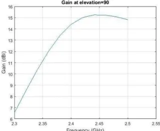
The sector antenna which is used for simulating the scenario produces a gain of 15 dBi at the frequency of 2.45 GHz. This tells that when operating on this frequency, this antenna will transmit 15 dBi more power in the direction of peak radiation than a lossless isotropic antenna. Figure 5 shows the relative gain at thedifferent frequency of the operating sector antenna.VSWR (Voltage Standing Wave Ratio) is the function of the reflection coefficient which is the power reflected back from the antenna. Lower the VSWR, the better is the antenna matched to the transmission line and therefore more power is transmitted to the antenna in ahilly area. The sector antenna which is used in simulation produces a VSWR of less than 2 dB at a frequency of 2.42 GHz. This shows that
at this frequency, maximum power is delivered to the antenna and less power is reflected back. These results are shown to justify that the antenna used is highly efficient for the simulation purpose and meets the purpose for the network coverage model. Figure 6 shows the VSWR comparison with different frequency.
Fig. 5 Gain vs Frequency comparison of a sector antenna
Fig. 6 VSWR at different operating frequency
IV.
CONCLUSION
used everywhere but still they’re not being used efficiently according to the geography of the area. The proposed solution promises the coverage using a combination of better antenna configuration, antenna types, and appropriate channel allocation strategies.
REFERENCES
[1] Arafat Abu Mallouh, Christian Bach and Abdullah A. Abdullah, Dynamic Channel Allocation in Cellular Networks, International Journal of Innovation and Applied Studies, 2013.
[2] Swati M. Khandare, R. R. Sedamkar, Efficient Scheme for Dynamic Channel Allocation Using Intelligent Agent in Mobile Communication, International Journal on Advanced Computer Engineering and Communication Technology.
[3] M. P. Mishra, P. C. Saxena, Survey of Channel Allocation Algorithms Research for Cellular Systems, International Journal of Networks and Communications, 2012.
[4] Jayshri Joshi, Girish Mundada, A Hybrid Channel Allocation Algorithm to Reduce Call blocking probability using Hot-spot Notification, IEEE, 2010
[5] I. Katzela and M. Naghshineh, Channel Assignment Schemes for Cellular Mobile Telecommunication Systems, IEEE Personal Communications, Vol:3, Issue:3, 1996.
[6] Alagu S, Meyyappan T, Dynamic Channel Allocation Scheme To Handle in Wireless Mobile Network, AIRCC Publishing Corporation, 2012.
[7] C. Beckman, B. Lindmark, The Evolution of Base Station Antennas for Mobile Communications, Electromagnetics in Advances Applications, 2007, ICEAA 2007.
[8] Mathworks,http://in.mathworks.com/help/antenna/e xamples/sector-antenna-for-2-4-ghz-wifi-tm.html
Author’s Biography
Mridul Mohan Bharadwajis pursuing his B. Tech in Computer Science from Manipal University Jaipur and is currently in thefinal year. His areas of interest are Mobile Computing, Data Structure, and Android Application Development. He got his motivation in the7th semester from the subject named “Mobile Computing” and therefore thought of doing research in the field of Cellular Antennas, Handoff and Network Coverage.
![Fig. 1 shows the horizontal radiation pattern of a 90- 90-degree Sector Antenna[8]](https://thumb-eu.123doks.com/thumbv2/123dok_br/18340530.351934/2.892.459.821.792.1038/fig-shows-horizontal-radiation-pattern-degree-sector-antenna.webp)