Fiabilitate si Durabilitate - Fiability & Durability no 2(8)/ 2011 Editura “Academica Brâncuşi” , Târgu Jiu, ISSN 1844 – 640X 61
TEMPERATURE MONITORING WITH PROGRAMMABLE LOGIC
DEVICES
Constantin STEFAN Ph. D, eng. Vasile-Paul NICOLAIESCU
University of Petrosani
Abstract: The monitoring system is conceived as an open system which allows the later development (hardware and software) both in process and operating stations and the communication system level. The facilities of multiprocessing allow the later development of the system capacity without being affected its functioning. A monitoring also means the knowledge and the monitoring of the operation from the operator panel (HMI) of each equipment without moving from the place to see its unfunctionality [1].
Keywords: HMI – Human Machine Interface;PLC – Programmable Logic controller;
1.General considerations
The monitoring system based on equipments with a programmable logic is used to realize the automation functions in performance field. The reliable construction if the monitoring system made it to be used by users in hard conditions of operation and environment, for example, in the vicinity of power equipments.
The hardware standard technology, the modular projection and the facilities (capability) of high performance programs offer to the system the following features [1]:
- an easy use in assembly or connection;
- easy change (replacement) with modular blocks;
- adaptability to use different inputs and outputs of power and tension;
- easy installation of the modules, vibration resistant, that are easy introduced in drawers;
- easy programming by structured programs and by the use of sections of standard programs ( function blocks);
- easy communication with other programmable automatons and computers by using internal processors or communication interfaces and LANs;
The automation plant also named automation system, together the technological and electrical plant from the main plant technology and with the exploitation personnel form the system of operative management.
The monitoring is structured by the following levels: - local individual monitoring;
- a monitoring centralized from a control room.
The facilities of multi processing allow the later development of the system capacity without being affected its functioning. The monitoring functioning supposes the operator notifies of all the information necessary to the knowledge of managed process evolution and the decisions of manual intervention over the process, direct (by manual commands of on/off, closing/opening), or indirect ( coupling/decoupling
from automated or sequential functions, as well as commands: increase-decrease by automated control loops when they are in automatic mode, etc.). By these interventions there is realized the monitoring function [2].
The monitoring and supervision functions ensure [4]:
- the interface with the operator that is simple, intuitive and flexible;
Fiabilitate si Durabilitate - Fiability & Durability no 2(8)/ 2011 Editura “Academica Brâncuşi” , Târgu Jiu, ISSN 1844 – 640X 62
properties;
- acoustinc and signaling when the monitored value overpassed a preset threshold; - the possibility to set two damage tresholds (preventive/emergency);
- the alarm will be maintained just to the moment when the triggering condition disappered and/or the operator confirmed it.
- the process command could be realized by:
the data introduction from the keyboard in fields configured by the user;
mouse selection from the command menu;
mouse selection in the selection table for fields.
software configurable buttons and acted touch-screen or with the mouse HMI technology (Human Machine Interface) ensures the human-machine interface (local monitoring) not being necessary for the man to move to the desired equipment placed to tens or hundred meters [4].
The achievement on the operator panel (HMI) of the technological plant supposes the detailed knowledge of the equipments that will be hardware assembled as well as the communication way between them. On the operator panel (HMI) there could be displayed different windows from a technological plant that includes equipments (monitoring, functioning fans, pipes, furnaces, water tank, temperature monitoring, actuator, sensors, thermocouples, mechanical action systems, product recipe, etc.) to their alarms and damages. The example below focuses on the local monitoring of a part from the plant of a technical treatment furnace that is its heating system.
The furnace heating is given by the step-down transformers of 24 Vac/4000A stress, providing several carbon composite resistance. The maintaining in parameters of a heating system is given by the thermal converter and pyrometers that are installed on sides of each zone.
To realize a monitoring system there are followed the next steps:
2. The hardware inclusion of field and command equipment. The field and command equipments are physically connected and the information providing to the operator panel or superior network (control room) is realized through a proper communication network (PROFIBUS or ETHERNET network). The configuration hardware system, is composed by [3.4]:
- programmable automaton; - HMI operator panel; - Thermocouples; - Pyrometers;
- Terminal box, they link the field elements and I/O digital and analogical modules; - Analogical inputs;
- Communication network (ex. PROFIBUS).
-3. Programming hardware plant. At the level of programmable automaton and operator panel HMI there are made the following operations:
- graphical interface of the thermocouples and their control;
- the achievement of the functioning logic of the thermocouples in process;
Fiabilitate si Durabilitate - Fiability & Durability no 2(8)/ 2011 Editura “Academica Brâncuşi” , Târgu Jiu, ISSN 1844 – 640X 63
The interface of field equipments on HMI panels is realized by a special soft named Win CC flexible, figure 1.
Fig.1 The thermocouples and pyrometers distribution in a heating module realized by WinCC flexible
On the operator panel there are displayed tags that go in a functioning logic from the programmable automaton. So, on the operator panel there are put the functioning parameters
of the following equipments (thermocouples, thermal resistance, pyrometers,…etc),
temperature diagrams, alarms and damages from the process ..etc.
Because of the different temperature bearings, the control of heating system is firstly made with thermocouples and after that there is used the heating control with pyrometers. In figure 1 there are monitored 10 parameters that measure the heat inside the module, thus:
- in the bottom and top side there are 4 thermal resistances (TT1501d...g; TT1601d...g) that measure the temperature to the module layer;
- to the left side there is located the thermocouple (TT901c) that measures the module isolation temperature;
- to right side there is located the pyrometer (TIT1601b) that measures the temperature inside the module form other heating bearing (cca 1200 C>).
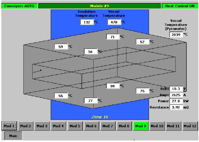
In figure 2 there is presented the window of heating system of the furnace from the operator panel HMI during its functioning.
This window gives us the following measured data: - “Insulation Temperature”;
-“Vessel Temperature”;
Fiabilitate si Durabilitate - Fiability & Durability no 2(8)/ 2011 Editura “Academica Brâncuşi” , Târgu Jiu, ISSN 1844 – 640X 64
To control the functioning of the heating resistance representative to the work area there are displayed the following data:
- resistance;
- resistance power;
- the current absorbed by the resistance;
- the heating system on “1 ON” position;
- the heating system on “0 OFF” POSITION;
Fig. 2 Temperature monitoring during the functioning
Fiabilitate si Durabilitate - Fiability & Durability no 2(8)/ 2011 Editura “Academica Brâncuşi” , Târgu Jiu, ISSN 1844 – 640X 65
Fig.3 The functioning logic of field equipment
Also in Win CC flexible there is programmed a window to see the variation in time of the temperature and of those 4 parameters of the heating element ( current, tension, resistance and power), see figure 4:
Fiabilitate si Durabilitate - Fiability & Durability no 2(8)/ 2011 Editura “Academica Brâncuşi” , Târgu Jiu, ISSN 1844 – 640X 66
4.Objectives
A system of operative management should ensure simultaneously management of the tehnological process and it should allow the exchange of information with the exterior to be as uniform as the achievement technique, operation and maintainance.
5.Conclusions
Therefore the solution of a management system shoul ensure:
- the safety increase in functioning of the plants, by avoiding the damages with effects over the personnel or equipments and the availability increase of productioncapacities; - the insurance of inexpensive exploitation by obtaining low consumption, of several
high yields and thus the obtaining of low production costs;
- the work conditions improvment by low operations volume that need physically effort and on this basis the qualification increase of operational staff;
- low necessity of routine activities, offering the possibility of minimizing of labor force implied in functioning activities, maintaining and administratice;
- a flexible communication concept that allows the access to all process data necessary to an operative management, a control system with programmable equipments that also allow the integration of different automation systems from different generations; - the infromation transmitting to a controlling network;
- the system opening to allow subsequent developments.
References
[1] David Bailey – Practical SCADA for Industry. Linare House, Jordan Hill Edwin Wright Oxford IDC Tehnologies 2003.
[2] Daniel Popescu - Automate programabile. Constructie, functionare, programari si aplicatii, Editura Matrix Rom, Bucuresti 2006.
[3] Documentatie Siemens – Manual de programare PLC.