Tese apresentada para a obtenção do grau académico de Doutor em Engenharia Civil na especialidade de
Reabilitação do Património Edificado, pela Universidade Nova de Lisboa, Faculdade de Ciências e Tecnologia
GROUT OPTIMIZATION FOR MASONRY
CONSOLIDATION
ANA MARGARIDA ARMADA BRÁS
Tese apresentada para a obtenção do grau académico de Doutor em Engenharia Civil na especialidade de
Reabilitação do Património Edificado, pela Universidade Nova de Lisboa, Faculdade de Ciências e Tecnologia
Grout optimization for masonry
consolidation
Ana Margarida Armada Brás
Orientador: Doutor Fernando M.A. Henriques, Professor Catedrático, Faculdade de Ciências e Tecnologia da Universidade Nova de Lisboa
Membros do Júri: Presidente
Doutor José Alberto Cardoso e Cunha, Professor Catedrático, Faculdade de Ciências e Tecnologia da Universidade Nova de Lisboa (por delegação Reitorial)
Vogais
Doutor Caspar Johannes Wilhelmus Petrus Groot, Professor Associado da Faculty of Civil Engineering and Geosciences, Delft University of Technology
Doutor Arlindo Freitas Gonçalves, Investigador Coordenador, Laboratório Nacional de Engenharia Civil Doutora Maria Paulina Faria Rodrigues, Professora Coordenadora, Escola Superior de Tecnologia do Barreiro, Instituto Politécnico de Setúbal
The people who get on in this world are the people who get up and look for the
circumstances they want, and, if they can’t find them, make them.
Agradecimentos
Ao Professor Doutor Fernando M.A. Henriques, orientador científico desta tese, um agradecimento especial pelo seu interesse, pela confiança depositada em mim, que me motivou a desenvolver este trabalho, contribuindo para o meu crescimento pessoal e profissional.
A autora foi bolseira de doutoramento ao abrigo da FCT/MCTES (SFRH/BD/19514/2004), o que tornou possível a realização deste trabalho dentro dos prazos estabelecidos (Março de 2006 a Março de 2010). O mesmo teve também apoio do projecto MASONGROUT - Grouts in the consolidation of old masonries (PTDC/ECM/72705/2006) que possibilitou a aquisição de equipamentos e a frequência de cursos e conferências.
Porque “nenhum homem é uma ilha isolada; cada homem é uma partícula do continente, uma parte da terra...” manifesto o meu profundo agradecimento a duas pessoas que contribuíram para o desenvolvimento deste trabalho segundo visões distintas da ciência: à Professora Doutora Teresa Cidade, do Departamento de Engenharia dos Materias da FCT/UNL e CENIMAT/I3N pela sua amizade e disponibilidade demonstrada na realização dos ensaios reológicos, em comentar e sugerir ideias, que se traduziram inclusivé na realização de artigos em conjunto; ao Professor Doutor Eric Didier, investigador no LNEC e no Departamento de Engenharia Mecânica e Industrial da FCT/UNL, pelos seus ensinamentos na área de Modelação Computacional em Mecânica dos Fluídos, pela disponibilidade em esclarecer as dúvidas na realização dos modelos computacionais, por comentar e sugerir.
A todos os colegas do Departamento de Engenharia Civil (DEC), nomeadamente aos Engenheiros Eduardo Cavaco, Rui Marreiros, Ana Rita Reis, Carla Marchão, Arquitecto Rui Vera Cruz, Professor Doutor Daniel Aelenei, Professor Doutor C. Chastre Rodrigues, Professor Doutor Rui Micaelo, Professor Doutor João Leal, pela amizade, boa disposição, apoio e incentivos prestados. Aos ex-professores de departamento, Professora Doutora Paulina Faria Rodrigues e Professor Doutor Vasco Moreira Rato, que contribuíram para o desenvolvimento do meu gosto em investigação e para que aqui chegasse.
Aos Técnicos Profissionais Jorge Silvério e José Gaspar do DEC pelo apoio prestado em inúmeras tarefas laboratoriais, pela sua dedicação e por contribuírem para um óptimo ambiente no local de trabalho.
Um agradecimento ao Engenheiro Carlos Galhano do Departamento de Ciências da Terra da FCT/UNL pelas imagens SEM dos ligantes; à Professora Doutora Ana Maria Ramos do Departamento de Engenharia Química pelos conselhos relacionados com viscosímetros.
À Engenheira Dina Frade da empresa Secil Martingança, Engenheira Ângela Nunes e Engenheiro Vitor Vermelhudo da fábrica da Secil no Outão, pelas matérias-primas e análises disponibilizados.
Ao Engenheiro Pedro Marques da LEB - Consultoria em Betões e Estruturas, Lda, pela ajuda prestada na aquisição de informação e materiais para a realização de caldas.
Aos Doutores Engenheiros Manuel Vieira e Paula Freire do LNEC, pela disponibilidade na realização das análises físicas a ligantes, nomeadamente a granulometria a laser. Ao Engenheiro Nuno Almeida do IST pela amizade e pela ajuda prestada em algumas análises granulométricas de agregados.
Resumo
A injecção com caldas (“grouts” em inglês) é uma das técnicas correntemente utilizadas na consolidação de alvenarias de pedra. O objectivo desta técnica é aumentar a compacidade da alvenaria, tirando partido do elevado nível de porosidade dos seus materiais, criando ao mesmo tempo uma ligação entre os panos interior e exterior. Deste modo, melhora-se não só a resistência ao corte e à flexão como também à compressão, permitindo que as cargas verticais e horizontais se distribuam de modo mais uniforme pelas três zonas da alvenaria.
A qualidade da consolidação depende quer dos materiais existentes, quer do desempenho geral da calda utilizada. As propriedades da calda no estado fresco revelam-se tão importantes quanto as que atinge no seu estado endurecido, na medida em que o seu desempenho global depende da capacidade da calda em penetrar na porosidade aberta. Consequentemente, a reologia das caldas deve ser compreendida e controlada, de modo a que possam ser bombeadas e fluam no meio poroso onde estão a ser injectadas. De facto, as caldas no estado fresco são um material com um comportamento que se pode considerar intermédio entre o de um fluido e o de um aglomerado húmido de partículas. Deste modo, poderão ser aplicados conceitos da reologia para a sua caracterização em função de propriedades intrínsecas reológicas como a tensão de cedência e a viscosidade que permitem avaliar e prever o comportamento das caldas.
Summary
Old masonries such as heritage or modest buildings represent a large portion of the construction area in many urban centres, such as Lisbon, Portugal. They frequently present a bad state of conservation and often require the need for consolidation in order to increase or maintain the structural characteristics. The purpose of a grout injection technique applied in a multiple leaf wall is to increase the compactness and create links between the internal and external leaves, which improve not only shear and flexural resistance but also the compressive strength. Therefore, consolidation quality depends upon the characteristics of masonry materials and on grout behaviour. Fresh grout properties seem to be as important as the ones in the hardened state since grout consistency is an essential characteristic to allow the filling of voids. Thus, the optimization of grout injection is a task of major importance.
The grout rheological behaviour is connected to its fresh properties. Therefore, rheology is a major tool for grout development since it enables not only the understanding of interactions between different ingredients, but also it may be used for quality control and grout design.
The research work aim was to develop an optimized methodology of grouts for masonry injection and consolidation. Before the development of the research, an extensive study concerning the state of the art on this subjected was made. Those notes are presented in Chapter 1 to 3 and they represent the tools needed for research development.
The goal was to get a good agreement between the numerical results and experimental values, in order to confirm the validity of the numerical approach and allow the use of those numerical results obtained for Marsh cone to predict grout flow time.
Notations and symbols
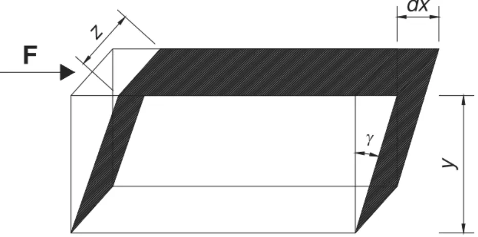
Shear stress
F Force
A Area of the top of element
Shear strain
t Time
.
Shear rate
Viscosity
0
Yield stress
Ratio between the solid phase volume and the mixture volume
m
Maximum packing fraction
c
Critical packing fraction
s
Viscosity of the suspending medium
w/b Water/ Binder ratio w/c Water/ Cement ratio
0
Viscosity at the first Newtonian region
Viscosity at the second Newtonian region
K2 Consistency
n Power-law index
s 0
Static yield stress
d 0
Dynamic yield stress
Flocculation level inside the material (structural parameter)
Characteristic time of evolution of the structure
Material parameter
thix
A Rate of flocculation
3
B Friction coefficient between particles
n3 Number of particles
0
U Initial degree of dispersion
H Coagulation rate constant
h Thickness of the second layer
c
t Critical time
p
Plastic viscosity
c Insignificant constant
Tlimit Grout threshold temperature
st
Steady state viscosity
I Injectability
inj
h Injection height
T Splitting tensile strength
P Maximum applied load indicated by the testing machine
l Length
d Diameter
FT Flow time
A
P Injection pressure in point A
B
P Injection pressure in point B
P
Pressure variation
CFD Computational Fluid Dynamic VoF Volume of Fluid
W
V Volume of decanted bleed water
1
V Volume of sample at beginning of test
ASTM American Standard specifications and Test Methods
MIX Mixture
EN European Standard
DEC/UNL Department of civil engineering of Universidade Nova de Lisboa FCT Faculdade de Ciências e Tecnologia
LNEC Laboratório Nacional de Engenharia Civil CV Coefficients of variation
C.I. Confidence Interval ANOVA Analysis of variance QC Quality Characteristic DOE Design of Experiments
Contents
Chapter 1: Introduction... 1
1.1 Aim and scope of the research ... 1
1.2 Limitations ... 2
1.3 Research objectives ... 3
1.4 The importance of correct judgements of grouts design for masonry consolidation ... 3
1.5 Thesis content ... 4
Chapter 2: Grout injection as a consolidation technique for masonry ... 5
2.1 Purpose ... 5
2.2 General description of masonry and causes of damage ... 5
2.3 Injection technique ... 12
2.4 Grout design for masonry: an overview ... 17
2.4.1 Inorganic binders ... 18
2.4.2 Organic binders ... 21
Chapter 3: Rheology of hydraulic binder suspension ... 23
3.1 Purpose ... 23
3.2 Introduction ... 23
3.3 The importance of rheological measurements ... 25
3.4 Classification of flow types ... 26
3.4.1 Newtonian fluids ... 26
3.4.2 Non-Newtonian fluids – time independent ... 27
3.4.3 Non-Newtonian fluids – time dependent ... 31
3.5 Factors influencing the rheology of hydraulic binder suspension ... 36
3.5.1 Forces acting on particles suspended in a liquid ... 37
3.5.2 Physical interactions ... 37
3.5.3 Influence of solid particles in rheology of suspensions ... 38
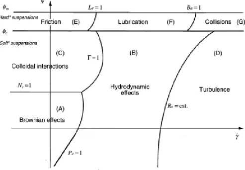
3.5.4 Rheophysical regimes of a suspension ... 39
3.5.5 Rheophysical regimes of a cement suspension ... 41
3.5.6 Range of interest of shear rate ... 42
3.5.7 Surface and colloid chemistry of thixotropic suspensions ... 44
3.5.8 Measurement techniques ... 46
3.5.8.1 Shear rate dependence ... 50
3.5.9 Thixotropy of hydraulic binder grouts - engineering consequences ... 56
3.6 Computational model of grout flow ... 59
3.7 Concluding remarks ... 62
3.8 References for Chapter 1 to 3 ... 63
Chapter 4: The influence of the mixing procedures on the optimization of fresh grout properties ... 71
4.1 Purpose ... 71
4.2 Introduction ... 71
4.3 Material Studied ... 72
4.3.1 Field of use and materials selection ... 72
4.3.2 Material characteristics ... 73
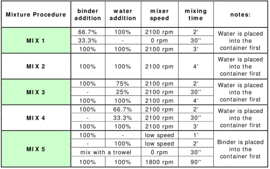
4.3.3 Mixing procedures ... 73
4.4. Water retentivity ... 76
4.4.1 Procedure ... 76
4.4.2. Results and comments ... 77
4.5. Study of the Rheological behaviour ... 80
4.5.1 Procedure ... 80
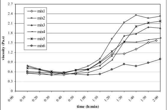
4.5.2 Results and comments ... 80
4.6. Study of grout bleeding versus stability ... 84
4.6.1 Procedure for bleeding test in freshly mixed grouts ... 84
4.6.2 Results and comments ... 85
4.7 Study of grout hardened properties... 87
4.7.1 Procedure for grout strength test, porosity and carbonation analysis ... 87
4.7.2 Results and comments ... 87
4.8 Discussion and conclusions ... 88
4.9 References ... 92
Chapter 5: Effect of environmental temperature and fly ash addition in hydraulic lime grout behaviour ... 95
5.1 Purpose ... 95
5.2 Introduction ... 96
5.3 Experimental ... 100
5.3.1 Material Studied ... 100
5.3.1.1 Scope ... 100
5.5.1 Introduction ... 103
5.5.2 Grout composition optimization ... 106
5.6 Procedure ... 108
5.6.1 Mixing procedures ... 108
5.6.2 Rheological measurements ... 108
5.6.3 Grout hardened properties tested... 109
5.6.3.1 Strength, dynamic modulus of elasticity and carbonation test ... 109
5.6.3.2 Mercury intrusion porosimetry and grout shrinkage ... 110
5.7 Results and discussion ... 111
5.7.1 Rheological tests ... 111
5.7.2 Strength, dynamic modulus of elasticity and carbonation ... 120
5.7.3 Mercury intrusion porosimetry and grout shrinkage ... 123
5.8. Main conclusions ... 125
5.9. References ... 127
Chapter 6: Effect of environmental temperature and fly ash addition in hydraulic lime grout behaviour-shear and time dependence ... 131
6.1 Purpose ... 131
6.2 Introduction ... 131
6.3 Material characteristics... 134
6.4 Procedure ... 136
6.4.1 Mixing procedures ... 136
6.4.2 Rheological measurements- time independent properties and temperature effect ... 136
6.4.3 Rheological measurements- time dependent properties ... 137
6.4.3.1 Procedure 1... 137
6.4.3.2 Procedure 2... 138
6.5. Results and discussion ... 139
6.5.1 Rheological measurements- time independent properties and temperature effect ... 139
6.5.2 Rheological measurements- time dependent properties ... 143
6.5.2.1 Procedure 1... 143
6.5.2.2 Procedure 2... 148
6.6 Main conclusions ... 151
6.7 References ... 153
Chapter 7: Grouts for masonry injection: how to select injection parameters - first approach..157
7.1 Purpose ... 157
7.3 Material Studied ... 160
7.3.1 Field of use and materials selection ... 160
7.3.2 Material characteristics ... 161
7.4 Procedure ... 163
7.4.1 Mixing procedures ... 163
7.4.2 Study of grout bleeding ... 163
7.4.3 Marsh cone test ... 164
7.4.4 Rheological measurements ... 164
7.4.5 Injection tests ... 165
7.4.6 Injection tests for injection curves determination ... 166
7.4.7 Splitting tests ... 167
7.5 Results and discussion ... 168
7.5.1 Bleeding test ... 168
7.5.2 Marsh cone ... 169
7.5.3 Rheological measurements ... 169
7.5.4 Injection tests ... 171
7.5.5 Injection tests for injection curves determination ... 180
7.5.6 Splitting tests ... 184
7.6 Main conclusions ... 185
7.7 References ... 189
Chapter 8: Computational modeling for grout behaviour prediction ... 193
8.1 Purpose ... 193
8.2 Introduction ... 193
8.3 Gambit ... 194
8.4 Fluent code ... 194
8.5 Implementation of grout flow simulation in Marsh cone test ... 196
8.6 Results and comments ... 200
8.7 Marsh cone improvement ... 203
8.8 Main conclusions ... 209
8.9 References ... 211
Chapter 9: Conclusions and recommendations ... 213
___________________________________________________________________________
List of Figures
Figure 2.1: Crack formation due to bending/splitting caused by hard cement
mortar among soft lime mortar ... 7
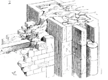
Figure 2.2: Example of a section of a three leaf masonry wall according to Viollet-le Duc ... 9
Figure 2.3: Damage detected in a masonry building repaired by introduction of concrete tie beams. Out-of-plane mechanism: separation of leaves. (Courradi et al., 2008) ... 10
Figure 2.4: In-plane shear failure of the masonry walls (Decanini L. et al., 2004) ... 10
Figure 2.5: Damage modes in masonry buildings. Out-of-plane masonry wall failure (a) and in-plane (shear) cracking (b). (b) shows wall ties securing the front facade from out-of-plane failure, which then imparts a greater load to the in-plane walls, initiating cracking (Decanini L. et al., 2004) ... 11
Figure 2.6: Modern injection installation according to (Van Rickstal, 2000) ... 13
Figure 2.7: Injection geometry using square pattern (21.5% not covered) (Van Rickstal, 2000) ... 14
Figure 2.8: Injection geometry using closest pattern (9.3% not covered) (Van Rickstal, 2000) ... 15
Figure 3.1: Deformation of an element of fluid due to an applied force F ... 24
Figure 3.2: Flow curve for a Newtonian behaviour ... 26
Figure 3.3: Viscosity curve for a Newtonian behaviour ... 27
Figure 3.4: Flow curve for a shear-thinning behaviour ... 28
Figure 3.5: Viscosity curve for a shear-thinning behaviour ... 28
Figure 3.6: Flow curve for a shear- thickening behaviour ... 29
Figure 3.7: Viscosity curve for a shear- thickening behaviour ... 29
Figure 3.8: Flow curve behaviour of viscoplastic (yield stress) fluids: 1) shear thinning, 2) Bingham plastic, 3) shear thickening ... 30
Figure 3.9: Different flow behaviour as a function of the applied shear rate in a material ... 31
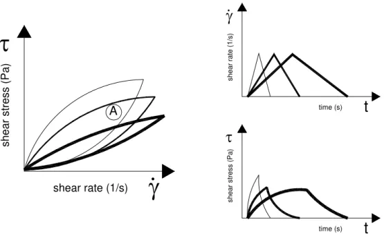
Figure 3.10: Representation of thixotropic material reaction due to loop change in the shear rate ... 33
Figure 3.11: Schematic representation of a thixotropic material where the rate of shear is changed stepwise ... 34
Figure 3.12: Stepwise increased shear rate with the material response as a reduced shear stress when the shear rate is constant (Billberg, 2006) ... 34
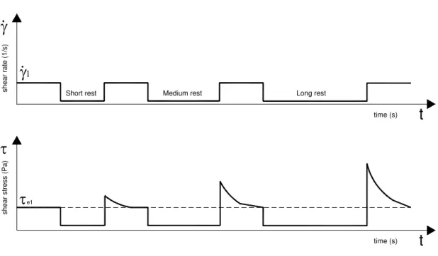
Figure 3.13: Structural build-up depending on resting time (Billberg, 2006) ... 35
___________________________________________________________________________
Figure 3.15: Rheophysical regimes of a cement suspension as a function of shear
rate and solid fraction on a logarithmic scale ... 41
Figure 3.16: Range of shear rate used in rheological measurements according to (Saak, 2000) ... 43
Figure 3.17: Slip layer next to the inner surface of the pipe during pumping of grout ... 43
Figure 3.18: Scheme of different fields of use of cement grout (Rosquoët et al., 2003) ... 44
Figure 3.19: Forces between atoms or molecules expressed as a pair potential energy (Cheng, 1987) ... 45
Figure 3.20: Brookfield viscometer LV DV-II+PRO (Bras et al., 2009) ... 48
Figure 3.21: Schematic diagram of basic toll geometries for the rotational rheometer: (a) concentric cylinder, (b) cone and plate, (c) parallel plate (Hackley et al., 2001) ... 49
Figure 3.22: Main parts in the rotational rheometer used in the present work: (a) gap size indicator; (b) device to determine the shear rate (or stress) response and a device to apply a constant torque (or rotation speed) to the tool, respectively; (c) measurement tool; (d) thermostatic bath with temperature control ... 50
Figure 3.23: Flow curve for a Herschel- Bulkley and Bingham fluid ... 51
Figure 3.24: Examples of transient behaviour: rotating speed increase ... 52
Figure 3.25: Examples of transient behaviour: rotating speed decrease ... 52
Figure 3.26: Rotating speed increase after a resting period ... 52
Figure 3.27: Visual summary of the most important aspects of the PFI-theory, based on (Wallevik J., 2009) ... 56
Figure 4.1: (A) and (B): Masonry grout injection ... 71
Figure 4.2: Mixer blade used in the experimental work ... 74
Figure 4.3: Stroboscope used in the experimental work ... 76
Figure 4.4: Device adopted for measurement of the water retentivity ... 77
Figure 4.5: Values of viscosity versus angular velocity for all mixtures using Program 1 ... 81
Figure 4.6: SEM image of natural hydraulic lime particle at 750x ... 82
Figure 4.7: SEM image of cement type I particle at 1500x ... 82
Figure 4.8: Values of viscosity versus time for all mixtures using Program 2 ... 83
Figure 4.9: Configuration adopted for the stability test ... 85
___________________________________________________________________________
Figure 5.1: Avalanche flow of a clay suspension over an inclined plane covered
with sandpaper. The suspension was pre-sheared and poured onto the plane, after which it was left at rest for 1 h. The pictures are taken at the critical angle for which
the suspension just starts to flow visibly (Coussot et al., 2002) ... 98
Figure 5.2: Improving quality by reducing variation around the target ... 103
Figure 5.3: Porosimeter used in tests ... 111
Figure 5.4: Shear stress versus shear rate for test 4 sample ... 112
Figure 5.5: Apparent viscosity versus shear rate for test 4 sample ... 112
Figure 5.6: Influence of factor effects on yield stress results ... 114
Figure 5.7: Influence of factor effects on plastic viscosity results ... 114
Figure 5.8: Influence of factor effects on consistency results ... 116
Figure 5.9: Influence of factor effects on power-law index results ... 117
Figure 5.10: SEM image of natural hydraulic lime particle at 1500x ... 118
Figure 5.11: SEM image of fly ash particle at 1000x ... 118
Figure 5.12: Influence of w/b effects on grout flexural strength results at 7 days ... 121
Figure 5.13: Influence of fly ash content on grout flexural strength results at 7 days ... 121
Figure 5.14: Influence of w/b effects on grout flexural strength results at 28 days ... 121
Figure 5.15: Influence of fly ash content on grout flexural strength results at 28 days ... 121
Figure 5.16: Influence of w/b effects on grout compressive strength results at 7 days ... 122
Figure 5.17: Influence of fly ash content on grout compressive strength results at 7days ... 122
Figure 5.18: Influence of w/b effects on grout compressive strength results at 28days ... 122
Figure 5.19: Influence of fly ash content on grout compressive strength results at 28days ... 122
Figure 5.20: Volume of pores in the three size categories for samples cured for 30 days and 120 days, for NHL5 based grout with 15% of fly ash ... 124
Figure 5.21: Cumulative shrinkage of NHL5 and NHL5+15% fly ash based grout (with w/b=0.70) from day 0 to 70 ... 125
Figure 6.1: Grain size distribution (in volume) of NHL5 and fly ash adopted in the tests ... 135
Figure 6.2: Procedure 1 for thixotropy test ... 138
Figure 6.3: Procedure 2 for thixotropy test ... 139
Figure 6.4: Flocculation area of NHL5 based grout according to the procedure adopted ... 139
___________________________________________________________________________
procedure adopted... 140 Figure 6.7: De-flocculation area of NHL5+ 15%fly ash based grout according
to the procedure adopted ... 141 Figure 6.8: Viscosity of NHL5 based grouts according to the procedure 1 ... 145 Figure 6.9: Viscosity NHL5+15%fly ash based grouts according to the procedure 1 ... 145 Figure 6.10: Initial shear stress obtained at a very low shear rate for NHL5
based grout after resting time ... 146 Figure 6.11: Initial shear stress obtained at a very low shear rate for
NHL5+ 15% fly ash based grout after resting time ... 146 Figure 6.12: Viscosity of NHL5 based grouts according to the procedure 2 ... 148 Figure 6.13: Viscosity of NHL5+15%fly ash based grouts according to
the procedure 2 ... 148 Figure 6.14: Shear stress of NHL5 based grouts according to the procedure 2 ... 149 Figure 6.15: Shear stress of NHL5+15% fly ash based grouts according
to the procedure 2 ... 150 Figure 6.16: Initial shear stress (filled bars) and corresponding steady state shear
stress (diagonal pattern) for NHL5 based grout (blue colour) and
NHL5+15%fly ash based grouts (green colour) ... 151
Figure 7.1: Grain size distribution for sand type “2-4” mm and “4-10”mm used
for cylinders grout injection ... 162 Figure 7.2: Grain size distribution for sand types “0-4”mm; “0-2”mm; “0-10”mm;
“2-4”mm and “4-10”mm used for cylinders grout injection ... 163 Figure 7.3: Cone test device according to EN445 ... 164 Figure 7.4: Setup for injection tests used in lab ... 166 Figure 7.5: Splitting test device adopted ... 168 Figure 7.6: Bleeding for different w/b ratios tested for a natural hydraulic lime
(NHL5) based grout ... 168 Figure 7.7: Flow time for 0 minutes after grout preparation for different w/b tested ... 169 Figure 7.8: Plastic viscosity and Yield stress values for NHL5 grout versus different
w/b (obtained from the downward curve) ... 170 Figure 7.9: Average of injection times in “2-4”mm media of grouts with different
water content and injection pressures ... 171 Figure 7.10: Cylinder filled by sand type “2-4”mm and injected with a pressure
equal to 1.0 bar by NHL5 based grout with w/b=0.60. Injection being
processed- non homogeneous filling ... 172 Figure 7.11: Cylinder filled by sand type “2-4”mm and injected with a pressure
___________________________________________________________________________
Figure 7.13: Grout with w/b=0.70 being injected in a cylinder filled by sand
type “2-4”mm. The injection filling is almost complete ... 173 Figure 7.14: Average of flow velocity for NHL5 based grout with different
water content, injected in the porous media “2-4”mm with different
injection pressure ... 174 Figure 7.15: Comparison of injection time values for NHL5 based grout with
different water content, injected in the porous media “2-4”mm and
“4-10”mm with p= 1.0 bar ... 175 Figure 7.16: Void with the shape of a cylindrical tube were flow occurs from A to B ... 178 Figure 7.17: Grout density before and after injection in the porous media
type “2-4”mm with p=1.0 bar ... 179 Figure 7.18: Injectability curves for water, NHL5 and NHL5+15% fly ash for
the different porous media tested, taking into account the % of the total mass that passes through nº40 sieve (0.425mm) ... 181 Figure 7.19: Injectability curves for water, NHL5 and NHL5+15% fly ash for
the different porous media tested, taking into account the porous media porosity injected ... 181 Figure 7.20: Dimensionless injectability curves for NHL5 and NHL5+15% fly ash
based grouts ... 182 Figure 7.21: Dimensionless injectability curves for NHL5 and NHL5+15% fly ash
based grouts for different media porosity ... 182 Figure 7.22: Poor section with very low content of voids (black filled)
(Laefer et al., 1996) ... 183
Figure 7.23: Percentage of mortar versus percentage of stones referred to the area of the cross section of stonework walls in various Italian regions
(Binda et al., 2001) ... 183
Figure 7.24: Size and distribution of the voids within the section of the wall
(Binda et al., 1997) ... 184
Figure 8.1: Marsh cone mesh generated with the software GAMBIT adopted in the
numerical simulations.. ... 197 Figure 8.2: Marsh cone boundary conditions adopted ... 198 Figure 8.3: Maximum average velocity of grout at the exit of Marsh cone for yielding
viscosity equal to 106 Pa.s ... 199
Figure 8.4: Flow time obtained using numerical simulation to fill a vessel with
1litre of NHL5 based grout with w/b=0.60 ... 201 Figure 8.5: Comparison of the flow times for 1litre of grout given by the
numerical simulation with the flow time measured experimentally ... 201 Figure 8.6: “New” Marsh cone shape used in numerical simulations as
___________________________________________________________________________
Figure 8.7: Flow time obtained using numerical simulation to fill a vessel with 1litre of
NHL5 based grout with w/b=0.70, for the new shape for Marsh cone... 205
Figure 8.8: Comparison of the flow times for 1litre of grout given by the
numerical simulation with the flow time measured experimentally, for the new shape for Marsh cone ... 205 Figure 8.9: Flow time for 0 minutes after grout preparation for different w/b tested
in the new Marsh cone device ... 208 Figure 8.10: Rheological results in terms of yield stress and plastic viscosity for
NHL5 based grouts with w/b= 0.60; 0.70 and 0.80 used in the
List of Tables
Table 2.1: Injection holes pattern with some recommendations found in recent
Literature ... 15 Table 2.2: Injection pressure values for masonry found in literature ... 16 Table 2.3: Injection capacity of different grouts in a certain porous media ... 17 Table 2.4: Mix proportions of selected grouts (%wt) and injectability
characteristics (Vintzileou, 2008) ... 20 Table 2.5: Grouts mechanical properties (Vintzileou, 2008) ... 20
Table 3.1: Viscosity of some familiar materials at room temperature ... 25 Table 3.2: Maximum packing fraction of various arrangements of
monodisperse spheres (Barnes et al., 2001) ... 39
Table 3.3: Energy for particles in a suspension depending on the interaction of
different type of forces (Pugh et al., 1994) ... 46
Table 3.4: Rheological models (Barnes et al, 2001) ... 50
Table 3.5: Applicability of some available numerical methods in the
cementitious materials field (Roussel et al., 2007)... 61 Table 3.6: Rheological recommendations for concrete ... 62
Table 4.1: Natural hydraulic lime characteristics ... 73 Table 4.2: Different mixing procedures tested for the same grout composition
(NHL5 with w/b=55%) ... 75 Table 4.3: Water retention time results for different mixing procedure ... 79 Table 4.4: Final bleeding for all mixtures procedure tested ... 86 Table 4.5: Strength and elastic modulus results for different mixing procedure
for NHL5 based grout with w/b=0.55 ... 88 Table 4.6: Porosity and carbonation depth at 28 day for NHL5 based grout
with w/b=0.55 ... 88
Table 5.9: Expected results at optimum grout composition (for a confidence
level of 95%) ... 119 Table 5.10: Strength results for different procedure for NHL5 based grout with
or without fly ash at 7days (temperature=25ºC) ... 120 Table 5.11: Strength results for different procedure for NHL5 based grout with
or without fly ash at 28 days (temperature=25ºC) ... 120 Table 5.12: Dynamic elastic modulus and carbonation depth for the optimum
procedure for NHL5 based grout with 15% of fly ash at 7 and 28 days of
age (temperature=25ºC) ... 123
Table 6.1: Natural hydraulic lime characteristics ... 135 Table 6.2: Density and fineness using Blaine permeameter of NHL5 and fly ash ... 136 Table 6.3: Results of the Tlimit, flocculation and de-flocculation values for the
equilibrium situation (the first region) ... 141
Table 6.4: Values of viscosity in the second Newtonian region (),
consistency (K2), power-law index (n), yield stress (0) and plastic viscosity (p) for
NHL5 based grouts and NHL5+15% based grouts tested ... 143
Table 7.1: Natural hydraulic lime characteristics ... 161 Table 7.2: Chemical characterizations of NHL5 according to SEM results ... 161 Table 7.3: Dmin of the porous media that could be injected for each w/b ratio
adopted in grout composition ... 179 Table 7.4: Porous media characteristics ... 181 Table 7.5: Indirect tensile test on injected cylinders at age 45 and 120 days
for NHL5 and NHL5+15% fly ash (w/b=0.70) ... 184
Table 8.1: NHL5 based grout properties used in computational simulations ... 196 Table 8.2: Mesh parameters adopted ... 198 Table 8.3: Reynolds number for each w/b ratio of NHL5 grout that flow though
Marsh cone ... 202 Table 8.4: Verification of the flow criterion for the tested grouts. ... 207
The following seven papers are included in the thesis and comprise part of the experimental work performed for the purpose of this thesis:
Bras A., Henriques F. (2008) Influência das propriedades de caldas no estado fresco na sua concepção para efeitos de injecção em alvenarias antigas. Proceedings of the 4th CINPAR - International conference on Structural Defects and Repair, Universidade de Aveiro, Junho 2008.
Bras A., Henriques F. (2008) Consolidation by grout injection technique- analysis of fresh grout properties. Proceedings of the 8th International Seminar on Structural Masonry, Istanbul Technical University, Istambul, 79-87 November 2008.
Bras A., Henriques F. (2009) The influence of the mixing procedures on the optimization of fresh grout properties. RILEM Materials and Structures 42: 1423-1432.
Bras A., Henriques F. (2009) Grout mix optimization for injection purpose -1st part of the
development. RILEM-Symposium on Rheology of Cement Suspensions - 3rd RILEM
International Symposium on Rheology of Cement Suspensions such as Fresh Concrete, Reykjavik, Iceland, 19th - 21st of August, 2009. Poster communication.
Bras A., Henriques F., Cidade M. T (2010) Effect of environmental temperature and fly ash addition in hydraulic lime grout behaviour. Construction and Building Materials Journal, Elsevier, doi:10.1016/j.conbuildmat.2010.02.001
Bras A., Henriques F. (2010) Investigation of grout parameters for masonry injection, using a natural hydraulic lime binder. Submitted to International Journal of Architectural Heritage: Conservation, Analysis, and Restoration, Taylor & Francis.
Chapter 1. Introduction
1.1 Aim and scope of the research
The research work aim was to develop an optimized methodology of grouts for masonry injection and consolidation.
In masonry, grouts (or pastes) designate a fluid mixture of binder, water and, possibly, admixture (see 2.4). The purpose of a grout injection technique applied in a multiple leaf wall is to increase the compactness and create links between the internal and external leaves, increasing not only shear and flexural resistance but also compressive strength. The correct grout selection should optimize two often competing properties, namely injectability and stability. The flow properties of fresh grouts are as important as their properties in the hardened state, since they govern the ability of the grout to fill a particular type of void. In practice, the variability of voids within masonry requires an ability to fine tune the rheological properties of the grout in order to optimally fill a given void. So, it was developed a methodology with the main purpose of finding not only the best mixing procedures but also the optimal grout composition from a rheological and injectability points of view.
The structural improvement of masonries is not only based on the increase of the mechanical resistances. Ductility and durability should also be taken into account since an incompatible choice of grout composition may jeopardize the performance of old masonries. However the focus was early limited to grout rheological and injection studies, selecting always grout composition based on durability and ductility criteria in order to ensure compatibility with the original materials to be injected.
Chapter 1. Introduction
Some historic and important masonry structures are “buildings at risk” and a correct building intervention and philosophy of repair is needed. Masonry conservation frequently requires the need for consolidation in order to increase or maintain the structural characteristics and here grout injection techniques may became an important solution.
1.2 Limitations
The numbers of parameters influencing masonry consolidation is quite large and many of them are not included in this research. The parameters included are mainly the grout material properties, the injection pressure which were chosen taking into account the masonry’s porous media to be injected.
Masonry characteristics are very different; some of them present only a single leaf and others multiple leaf walls. The connection between the leaves may be different as well as the filling material of the internal leaf. In the case of a multiple leaf wall, the section is composed by two resistant external leaves and an internal layer filled by small stone pieces, sand, mortar or other kind of unbounded material. The absence of cohesion among elements, the existence of voids and cracks as well as the deficient connection between leaves lead to a masonry non-monolithic behaviour. This means that the wall becomes brittle, namely under vertical and horizontal loads. Therefore, shear and flexural strength are affected and deformation and failure of the two external leaves may occur, which indeed justify the use of grout injection technique for consolidation.
Chapter 1. Introduction
1.3 Research objectives
The research lines proposed in this work were the following:
1. Analyze the influence of the mixing procedure in grout behaviour and how it may improve some essential injection characteristics.
2. To study the influence of environmental temperature and of the addition of fly ash (a by-product of the combustion of pulverized coal in thermal power generation that was used in some grouts since it reduces the costs and the environmental impacts) in fresh grouts behaviour. An attempt was made to achieve an optimal grout composition by using the Taguchi method.
3. To study the effect of temperature and/or fly ash in grout thixotropy and flocculation rate and to know if it is possible to regulate and reduce masonry pressure during and after grout injection if thixotropic parameters are controlled.
4. To increase the knowledge about the physical mechanisms that take place during grout injection and to define a right composition for grouts to be used for the strengthening of walls, enabling also grout design regarding several issues like best injection pressure to adopt.
5. Adopt computational modelling for grout design.
1.4 The importance of correct judgements of grouts design for masonry
consolidation
Consolidation quality depends mainly on masonry materials characteristics and on grout behaviour. Fresh grout properties seem to be as important as the ones in the hardened state, since grout consistency should allow the voids to be filled. Those fresh grout properties are really important especially if the injected region is inaccessible for visual inspection (except when using destructive tests).
Chapter 1. Introduction
The purpose of performing rheological measurements is not only to understand the interactions between different ingredients in a grout, but also for quality control of products and processing conditions. Results obtained in rheological tests can be used to design process equipment (like pumps) or to be used by a customer to determine the acceptance of a product.
1.5 Thesis content
Chapter 2. Grout injection as a consolidation technique for
masonry
2.1 Purpose
In this chapter it will be given a brief and general description of masonries, some of its
typologies and damage mechanisms. Concerning masonry conservation, it will be presented
the grout injection technique as one of the techniques most widely used in the consolidation
of this type of buildings, to increase or maintain the structural characteristics. The definition
of grouts should deal with the description of the function of the grout and for that some
definitions will be presented. Concerning grout injection, there are two main categories of
materials that may be used: inorganic and organic binders. The following topics present some
material characteristics.
2.2 General description of masonry and causes of damage
Masonry exists for many centuries and has been in constant evolution since the placing of big
stones one on top of each other to the agglomeration of fine prefabricated stones and mortar
that is used today. To develop and use structural consolidation techniques, the designer must
start from the study and thorough understanding of the real nature and behaviour of masonry.
Masonry is a composite material, made of stones and mortar, bricks and mortar, or stones,
bricks and mortar. Not only the nature of mortar and stones can account for the type of
deterioration of the masonry, also the structural built up plays an important role (Van
Rickstal, 2000), (Van Gemert et al., 1997).
Most buildings were erected using the stones available in the neighbourhood such as granite,
marl, limestone or sandstone. Those natural stones withstand poorly the effect of acid rain
(especially the last ones). When the replacement of natural stones is necessary, they should be
similar to the original stones, with the same composition, the same porosity providing similar
properties with regard to water transport and the same frost resistance.
Chapter 2. Grout injection as a consolidation technique for masonry
masonry of natural stone, especially in valuable monuments since natural stones gave the
building an image of wealth and were known to be very durable. The replacement of natural
stones can be problematic if the quarries are no longer exploited. Besides, many natural stones
undergo an accelerated weathering because of air pollution. The original stones and the
replacing stones have a different structure and because of small differences in the weathering
resistance, the homogeneous outlook of the facade is disturbed. The fabric of natural stones in
the old artisanal way is expensive. The knowledge, the tools and the workers are not readily
available.
Mortar consisting primarily of lime and sand, has been used as an integral part of masonry
structures for thousands of years. Traditional mortar was made from lime putty, or slaked
lime, combined with local sand, generally in a ratio of 1 part lime putty to 3 parts sand by
volume. Often other ingredients, such as brick dust, clay, natural cements, pigments, crushed
sea shells (also a source of lime) and even animal hair were also added to mortar. However,
the basic formulation for lime putty and sand mortar remained unchanged for centuries until
the advent of Portland cement or its forerunner, Roman cement, a natural hydraulic cement. In
the 1930s more new mortar products, intended to accelerate and simplify masons' work, were
introduced. These included masonry cement, a premixed, bagged mortar which is a
combination of Portland cement and ground limestone, hydrated lime, machine-slaked lime
that eliminated the necessity of slaking quicklime into putty at the site (Van Rickstal, 2000).
2
3 heat( 900ºC) CaO CO
CaCO (2.1)
2
2O Ca(OH)
H
CaO (2.2)
O H CaCO CO
OH
Ca( )2 2 3 2 (2.3)
During the production of hydrated lime several chemical reactions take place. The calcium
carbonate (that could be found in lime stone or in shells) is dissociated at high temperature
(Eqn. 2.1). Then, the calcium oxide is slaked with water originating calcium hydroxide (Eqn.
2.2). Reaction (Eqn. 2.3) is using CO2 and hence requires the presence of air. For a thick wall,
this is always a problem.
To achieve some hydraulic properties to lime mortars, natural or artificial pozzolans should be
used. A pozzolan is an amorphous and finely-divided material that reacts with calcium
hydroxide, in the presence of water, to form compounds possessing cementitious properties.
Chapter 2. Grout injection as a consolidation technique for masonry
are produced when pulverized coal is burned in electric power plants (like fly ash). The
hydraulic properties gave these mortars a good early strength development.
However, the use of the relatively soft air hardening lime mortar gave ancient masonry a good
capacity to recover from settlements. The lime mortar has a slow strength development and
for historical buildings that were constructed slowly, this was not a big disadvantage. On the
contrary, deformations during the construction were distributed and moderated the stresses.
Besides that, the mortar remained less strong than the stones and occurring cracks were
located in the mortar joints, where they could easily be hidden by repointing. Generally, a
lime mortar is more elastic and this provides an additional safety with regard to differential
settlements. Lime mortar contains no or hardly any sulphate or alkalis. This reduces the risk
for salt efflorescence.
The previous statement implies that there are two main reasons to use mortars that are
compatible with the original mortars. The first one is the fact that using a modern mortar
would result in introducing a component that is harder than the old mortar and in most cases
also harder than the stones that were used. Settlements become hard to follow and
bending/splitting action caused by hard cement mortar among soft lime mortar may occur.
According to van Rickstal, the new hard cement mortar among soft lime mortar splits the
masonry just above the hard zone since the zone on the left and right hand side of the new
mortar are softer and more deformable (Fig. 2.1). Besides that, a cement mortar has a different
porosity causing a different action with regard to water transport.
The second main reason to use mortar compatible with the original ones regards what is
mentioned in the Venice Charter (Venice Charter, 1964) is to use mortars that imitate the
original mortar and that are as hard as the original one or even somewhat softer. Obviously
these statements will regulate grout composition to apply in masonry.
Brick/stone crack
mortar lime
Chapter 2. Grout injection as a consolidation technique for masonry
Also the repointing action should be carefully adopted in masonry joints since it is often an
important action in the restoration of facades. An appropriate mortar should be adopted. The
aim of this repair is to bond the stones of the external leaves, particularly in the case of badly
bonded irregular stones and to obtain an external confinement of the wall in order to increase
the masonry shear strength and avoid water penetration. The repointing can be carried out also
in conjunction with grout injection.
When disregarding the original composition, the new mortar used for repointing is almost
impermeable to water vapour in comparison with the original situation. Therefore, the water
vapour concentrates behind the repointed layer and salt crystallization or frost can then easily
push the new layer outwards causing even more damage since the adhesion of the repointed
mortar to the existing bricks or stone is very good. Generally, repointing should be limited to
the damaged parts, using a mortar composition that corresponds as well as possible with the
mortar used for the original pointing. Very often, a consolidation injection is combined with a
partial or general repointing (Van Rickstal, 2000), (Courradi et al., 2008).
There are several causes of damage to masonry. Some of them were already presented.
Generally they could be divided into: physical and physico-chemical mechanisms; biological
mechanisms and mechanical damage. Quite often physical and physico-chemical mechanisms
are induced by the presence of water, both in liquid or vapour forms and mostly need a long
period of time to cause visible damage. The presence of moisture depends of the location and
environmental conditions of the masonry, while transport is a function of porosity and pore
sizes of the masonry.
Moisture transport inside the masonry is a potential cause for lixiviation, a phenomenon that
may cause a decrease of internal cohesion. Freeze-thaw action or the presence of hygroscopic
salts may cause physical damages due to the increase of volume induced by crystallization.
When water is inside masonry, hydrofobic treatment should not be applied. The outer layer of
the masonry becomes impermeable to water. Only water vapour is able to be transported. This
means a much slower process of loss of water then when the water is able to proceed to the
surface itself. In this way two phenomena take place: spalling off of the treated outer layer of
masonry caused by hygroscopic salts growth due to the slower transport of water inside;
decrease of the internal cohesion since moisture movements give rise to the dissolution and
Chapter 2. Grout injection as a consolidation technique for masonry
Grout injection is very suitable to repair this kind of damage. The more uniform the grout fills
the voids caused by the erosion of the binder, the better the final consolidation.
Atmospheric pollution has also a great impact on masonry given the fact that new ions may be
added to those already existing inside the masonries, thus increasing the risk of physical or
chemical damages. Corrosion of metallic elements may also occur, inducing fissures and
cracks in masonries or colour changes.
Concerning the biological damage, the formation of algae, fine roots of plants or the micro
organisms that bring bacteria that produce nitrates and sulphates as residue of their
metabolism, are also some of the possible damage mechanisms.
Mechanical damage may be caused by mistakes in the original design of masonry or even by
a different use of the building, for instance a dwelling building converted to a gymnasium
(were the load is much higher than the designed load). However, those problems are not only
due to human actions. Earthquakes, wind, rain or storms can cause severe damage.
Mechanical damage is very suitable to be repaired by grout injection.
Masonry types are very different; some of them present only a single leaf and others multiple
leaf walls and these cannot be compared to brick or regular stone-masonries. The connection
between the leaves may be different as well as the filling material of the internal leaf. In the
case of a multiple leaf wall, the section is composed by two external leaves and an internal
layer filled by small stone pieces, sand, mortar or other kind of unbounded material (Fig.2.2).
Chapter 2. Grout injection as a consolidation technique for masonry
The absence of cohesion among elements, the existence of voids and cracks as well as the
deficient connection between leaves lead to a masonry non-monolithic behaviour. This means
that the wall becomes brittlier, namely under vertical and horizontal loads. Therefore, shear
and flexural strength are affected and deformation and failure of the two external leaves may
occur. Those leaves tend to separate (Fig. 2.3) and a partial or total collapse of the wall can
take place (out-of-plane mechanisms). This mechanism of collapse has frequently occurred
during seismic events.
One of the most difficult tasks for engineers and architects is the repair and/or retrofit of this
damage. Traditional masonry works are also particularly susceptible to in-plane shear actions
due to their very low tensile strength, so reinforcement should prevent both out-of-plane and
in-plane collapse mechanisms (Fig. 2.4 and 2.5) (Courradi et al., 2008), (Penazzi et al., 2001).
Figure 2.3: Damage detected in a masonry building repaired by introduction of concrete tie beams. Out-of-plane mechanism: separation of leaves. (Courradi et al., 2008).
Chapter 2. Grout injection as a consolidation technique for masonry
Figure 2.5: Damage modes in masonry buildings. Out-of-plane masonry wall failure (a) and in-plane (shear) cracking (b). (b) shows wall ties securing the front facade from out-of-plane failure, which then imparts a greater
load to the in-plane walls, initiating cracking (Decanini et al., 2004).
Masonry conservation frequently requires the need for consolidation in order to increase or
maintain the structural characteristics. Grout injection is one of the techniques most widely
used in the consolidation of this type of buildings, to improve the masonry shear and flexural
strength. The purpose of this technique is to increase the compactness of the masonry and, at
the same time, create links between the internal and external leaves, therefore increasing its
resistance and the monolithic behaviour.
According to Schueremans et al. (Schueremans et al., 1998), the grout injection technique
increase masonry reliability, since one of the main goals is to improve the average strength
and/or reduce the variance on the strength between different masonry sections. However, the
grouts to be used for the injection should be correctly designed to achieve the maximum
performance. It means that besides strength, principles such as masonry ductility and
durability should be taken into consideration since a bad choice of grout composition may
jeopardize the performance of old masonries.
The efficacy of consolidation techniques depends upon masonry materials characteristics and
on grout behaviour in fresh and hardened state. The optimization of grout injectability
involves an adequate control of fresh properties, namely: the rheological properties (so that
the fluid may be pumped and flow inside the porous medium), water retention and bleeding,
among others, which allows the grout to flow easily inside the porous media avoiding that an
excessive loss of its mixing water may occur as a consequence of the medium absorption
Chapter 2. Grout injection as a consolidation technique for masonry
In this way, the grout specification involves a previous verification of the following items:
1. Grout flow capacity inside the porous media;
2. Grout composition compatible to the original materials used in masonries.
This flow capacity and the ability to fill the voids, together with a suitable grout composition,
will regulate the consolidation quality.
2.3 Injection technique
Grout is a binder employed for the filling, homogenization, imperviousness, consolidation
and/or upgrading of the mechanical properties of systems presenting pores, voids, cracks, loss
of cohesion or of cohesionless systems (like masonry) (Toumbakari, 2002). The binding agent
will cure and increase the internal cohesion of masonry, increasing also its monolithic
behaviour, together with the load capacity.
Since the grout is introduced into the internal part of masonry it does not damage the
aesthetical outlook of the building. However, grout injection is not reversible but when
materials are used that comply with the original materials, it is an acceptable technique in
accordance with the Venice Charter (Van Rickstal, 2000).
The use of fluid grout avoids dismantling and rebuilding defective masonry in many cases and
there is a choice of three basic methods for grout injection technique: gravity systems; hand or
mechanical pumped systems and vacuum systems. The nature and condition of masonry
selects the best method. Gravity technique is particularly suitable where the masonry is very
vulnerable to movement under pressure. Pumped systems of various kinds may be used to
deal with most grouting problems. Vacuum systems may be useful where fine fractures and
small-scale voids are suspected (Ashurst, 1990).
An injection installation generally consists of a complete set of device such as: mixing
installation (that mix the materials to be injected); collector (which collect and stirs the grout
previously mixed); pumping installation (which is fed by the collector and provide pressure
control); conduits (flexible tubes that lead the grout from the ground installation to the
injection hole). For longer distance between pumping installation and injection holes, a return
conduit should be present. If there is no return conduit, the grout will stand still in the main
Chapter 2. Grout injection as a consolidation technique for masonry
depending features of the grout to occur: instability and thixotropy. It depends on the quality
of the grout to what extent these phenomena will arise.
Before conducting an injection the diagnosis of the masonry should be made and for that, non
destructive and slightly destructive techniques are applied. Non destructive tests are very
suitable to obtain a qualitative picture of the masonry structure and to decide about
consolidation and for the quality control after injection. They are ideal to compare the initial
state with the injected one. Among the slightly destructive techniques, coring is probably the
most frequently used. The coring enables furthermore to judge the quality of the inner
masonry by visual inspection of the cores. Compressive and splitting tests can be performed
on the cores to get an idea of the mechanical properties of the masonry. Eventually the core
hole can be inspected using an endoscope. There are several techniques but it is not the
purpose of this thesis to develop this subject.
Nowadays there are also numerical and probabilistic methods that have been in development
to quantify the need, the benefit and the efficiency of an injection.
Chapter 2. Grout injection as a consolidation technique for masonry
The preparation of masonry obeys to several issues. Once the areas to inject are determined,
the building is prepared for injection and for that masonry should be sealed to prevent the
leakage of the grout. Therefore, a general repointing is recommended. Besides, a general deep
repointing can be seen as a very effective structural intervention. The repointing as such
already consolidates the masonry and must be fairly porous to not absorb the water of the
injected grout (Courradi et al., 2008), (Ashurst, 1990).
Nevertheless leakage can still occur and should then be stopped using quick-setting cement
cleaned immediately. Leakages prevent to build up pressure inside the flow channels. If the
stability of the masonry is very doubtful and if hydrostatical pressure is feared to arise, an
external reinforcement can be justified.
After repointing, the second part of the preparation is the drilling of the injection holes.
Generally they are drilled in the joints and in this way they will be less visible afterwards. The
holes should incline downwards and placed according to a certain pattern, density and depth.
Those parameters depend on the type of masonry, the overall condition of the masonry, the
rheological properties of the grout and incidence of cracks. A zone with many cracks will be
easier to inject and hence the pattern in this zone can be less dense. On the other hand the
applied pressure in this zone should be lower. Therefore and for reasons of simplicity the
density is often kept constant for the whole structure. Existing major cracks can easily be used
for injection.
Two possible geometries for injection are presented in Figure 2.7 and 2.8. Each circle
represents the injection area of a hole. The closest pattern increases the covered surface by
injection compared to the square pattern.
Chapter 2. Grout injection as a consolidation technique for masonry
Figure 2.8: Injection geometry using closest pattern (9.3% not covered) (Van Rickstal, 2000).
The recommended number of holes per square meter found in literature is mentioned in Table
2.1. The density of the injection holes is expressed as holes per square metre.
Table 2.1: Injection holes pattern with some recommendations found in recent literature. Reference nº of holes/m2 Comments
(Binda et al., 1991) 2 The holes should at least reach the 2/3 of the wall
(Baronio et al.,
1992) -
2-4 holes/m2 is not enough. The covered area for one injection hole depends on the penetration of the grout inside the masonry
(Van Rickstal,
2000) -
Closest pattern of the injection holes is preferable, density can vary depending on the
quality of the masonry
(Toumbakari, 2002) 4,5
Slightly inclined holes, preferentially drilled inside the mortar and not in the stones or
bricks
(Valluzzi, 2005) 11, 12
Only 70% of these holes were injected. The remaining 30% was used to check the diffusion of the grout during the intervention
During injection, when a grout reaches a large void, no pressure can be built up in the
neighbourhood of that void. Due to this low pressure, the grout will enter the fine cracks only
over a short distance. Thixotropy, water absorption and instability of the grout cause the
blocking for further injection in these finer cracks. When the large void is finally filled, the
pressure can increase again, but too much water of the grout is absorbed in the fine cracks to
Chapter 2. Grout injection as a consolidation technique for masonry
account not only porous media properties but also grout properties and injection pressure
(Van Rickstal, 2000),(Toumbakari, 2002), (Bras et al., 2008).
The injection pressure is the pressure at the inlet towards the injection holes and that enables
the penetration of the grout inside the masonry. The higher the pressure the easier and faster
the grout will pass and because of that, the grout will loose less water by absorption and the
particles will remain better in suspension. However, the pressure is limited to a few bars since
the internal pressure of the grout introduce tensile stresses that can not be taken by the
masonry. Increasing the pressure would soon cause additional damage to the structure. The
internal pressure in masonry is the addition of the hydrostatic pressure (proportional to the
height of the injected grout column that is still in fluid state) and the injection pressure
(controlled by pump).
Therefore, it is recommended not to inject the holes in a vertical order. Typical compressive
stresses in ancient masonry are about 1 MPa and tensile stresses are close to zero so, internal
pressure might cause big tensile stresses or might push out the outer leaf of the masonry.
Generally, the injection stop criteria for one hole in masonry are the following: the pressure
exceeds permanently the injection pressure; the grout emerges freely at adjacent injection
holes; a predetermined quantity of grout is injected in that hole. In Table 2.2 some
recommended values for the injection pressure are given.
Table 2.2: Injection pressure values for masonry found in literature.
Reference pressure (bar) Type of grout (Courradi et al.,
2008) 1.0 Hydraulic lime based grout (w/b=?) (Courradi et al.,
2008) 1.0 Albaria Iniezione 100
(Binda et al., 1997) 0.2 to 0.6 Micro fine cement based grout (w/b=1.5) (Binda et al., 1997) 0.2 to 0.6 Hydraulic lime grout (w/b=0.80)
(Binda et al., 1997) 0.2 to 0.6 Hydrated lime mixed with dust bricks (w/b=?) (Keersmaekers et al.,
2006) 1.0 CEMIIIA 42.5+Ca(OH)2 (w/b=0.675)
(Valluzzi, 2005) 0.5 Hydraulic lime based grout (w/b=0.55)
Binda and colleagues in (Binda et al., 1997) suggest a type of grout able to be injected in a
certain porous medium. The following table (Table 2.3) is based on those results. It can be
observed that the presence of silt and clay make the injection more difficult, due to their very
Chapter 2. Grout injection as a consolidation technique for masonry
and clay can only be injected up to a certain point with acrylic resins. However, they have
inconveniencies, like poor bond to wet surfaces, low resistance to thermal stresses. Besides
that, exothermic phenomena can take place when resins are injected in large voids, causing
damages to the wall itself.
Table 2.3: Injection capacity of different grouts in a certain porous media.
Grouts gravel sand silt clay
coarse medium fine
Suspe
n
sion
microfine cement
cement
bentonite
sodium silicate cement
S
o
lu
ti
on
acrilic resins
grain size (mm) 2 0.5 0.25 0.074 0.005
injection capacity higher
2.4 Grout design for masonry: an overview
There are several definitions of grout in cement and concrete literature. In the context of
masonry (Ashurst, 1990) defines grouting as the introduction of a binding agent in the form of
liquid into masonry or soil. (Toumbakari, 2002) defines grout as a binder employed for the
filling, homogenization, imperviousness, consolidation and/or upgrading of the mechanical
properties of systems presenting pores, voids, cracks, loss of cohesion or of cohesionless
systems. According to (Vintzileou, 2006)grout may be defined as a binder (either inorganic
or organic) injected to masonry with the purpose to fill cracks, voids and (to some extent)
pores of the in situ materials. In conclusion, the definition of grout should deal with the
description of the function of the grout.
Over the past two decades, grouts (especially cement based) have been used for an increasing
number of structural purposes, with more and more demands being placed on the grout. Many
of these developments have been made possible by the use of cement replacement materials
such as: silica fume, pulverised fly ash, blast furnace slag, metakaolin, admixtures, among
others (Sonebi, 2006), (Fernàndez-Altable et al., 2006), (Mirza et al., 2002),(Van Gemert et
al., 1997) which are now widely accepted as giving economic and technical advantages,
Chapter 2. Grout injection as a consolidation technique for masonry
Concerning grout injection, there are two main categories of materials that may be used:
inorganic and organic binders. The following topic presents some materials characteristics.
2.4.1 Inorganic binders
Binders obtained from inorganic raw materials include hydraulic binders such as: hydraulic
lime(s), ordinary Portland cement and all other types of modern cements, lime-pozzolan
mixtures; and air-hardening binders, such as hydrated lime.
Hydrated lime grouts cannot contribute to the repair and even less to the strengthening of
masonry since they require the presence of carbon dioxide for hardening. It is known that the
diffusion of air at the interior of the masonry mass is a slow process. This leads to a very slow
hardening and, consequently, a very slow increase of the mechanical properties of this binder
(sometimes hardening does not even occur).
On the contrary, hydraulic grouts present a very interesting option for the composition of
injection grouts since they are both from the chemical-physical and mechanical point of view
more adequate for use in historic masonries, provided that they are adequately designed.
Hydraulic binders may be subdivided into two main categories, namely cement and hydraulic
lime based grouts. Cement based grouts were initially pure cement grouts. However, it was
proven that their injectability properties were inadequate for filling the small size voids and
cracks of historic masonries because of clogging (Eklund et al., 2008), (Axelsson et al.,
2009), (Vintzileou, 2008)). Due to this behaviour Miltiadou in (Miltiadou, 1990) studied the
addition of ultra fine materials to cement material (on the basis of specific granularity
criteria).
In this way, grouts of high injectability and adequate mechanical properties were reached at
the same time. In order to serve the specific needs of each historic structure there is the need
for a wide range of mechanical properties of grouts to be available. Thus, binary grouts
(mixes of cement and hydrated lime, natural or artificial pozzolans, silica fume, etc.) and
ternary grouts (cement, hydrated lime and natural or artificial pozzolans) were developed.
Grouts with cement percentage varying mainly from 50% to 75% reach compressive strengths
varying between 10 to 30 MPa with a tensile strength range of 1.2 to 3.0 MPa (Miltiadou,