Miguel António Felizardo da Costa
Mestre
Advanced Instrumentation for
Superheated Liquid Detectors
in Dark Matter Searches
Dissertação para obtenção do Grau de Doutor em
Engenharia Física
Orientador: Doutor Thomas Abbott Girard
Co-orientador: Doutora Maria Adelaide de Almeida Pedro de Jesus
Júri:
Presidente: Prof. Doutor Fernando Jorge da Silva Pina
Arguentes: Prof. Doutora Maria Isabel Silva Ferreira Lopes Prof. Doutor Sérgio Eduardo de Campos Costa Ramos
Vogais: Prof. Doutora Maria Adelaide de Almeida Pedro de Jesus
Prof. Doutor José Joaquim Gonçalves Marques
Prof. Doutor Thomas Abbott Girard
Title: Advanced Instrumentation for Superheated Liquid Detectors in Dark Matter Searches Name: Miguel António Felizardo da Costa
Faculdade de Ciências e Tecnologia e a Universidade Nova de Lisboa
Copyright
ACKNOWLEDGEMENTS
This thesis was a massive undertaking for me. Tenacity and persistence were fundamental for
the accomplishment of this work. I would like to give a particular emphasis to the support and help that
I received.
My first words of gratitude are for Prof. Tom Girard and Prof. Adelaide Jesus, who being my
advisors were always rigorous, demanding and, above all, available.
I would like to acknowledge the Department of Physics from the Faculdade de Ciências e
Tecnologia da Universidade Nova de Lisboa, Instituto Tecnológico e Nuclear from Instituto Superior
Técnico and Laboratoire Souterrain Bas Bruit for accepting me to develop the work.
To Fundação para a Ciência e Tecnologia for the finacial support (SFRH/BD/46545/2008).
I am thankful to the SIMPLE collaboration in receiving me as a PhD student.
My last words, go of course, to my family; always helping, trying, and having an incredible
Title: Advanced Instrumentation for Superheated Liquid Detectors in Dark Matter Searches Name: Miguel António Felizardo da Costa
Dissertation for doctoral in Physics Engineering Supervisor: Doctor Thomas Abbott Girard
Co-Supervisor: Doctor Maria Adelaide de Almeida Pedro de Jesus
A
ABBSSTTRRAACCTT
The initial goal of the thesis work was to improve the performance of the instrumentation used in the SIMPLE dark matter search. Consequently, the ultimate objective is to find a possible candidate for Dark Matter or improve the knowledge of its nature. Upon a brief description of Dark Matter and the status of its search, the fundamentals of Superheated Liquid Detectors are presented.
This thesis presents a robust acoustic instrumentation together with a new method for the identification of bubble nucleations in Superheated Droplet Detectors. This is accomplished through straightforward signal processing techniques applied to the acoustical recording of the nucleation events, which consists of pulse shape identification procedures. A set of tests are presented to evaluate the performance of the proposed algorithms, as well as the new and more reliable instrumentation. An effort to locate a bubble nucleation in the SDDs is accomplished through some elaborated signal processing techniques applied to the acoustical recording of the nucleation events. These include the application of wavelets, the chirp-z transform and pulse shape identification procedures to locate temporally and validate the nucleation for its spatial localization. Acoustic and SDD associated backgrounds are completely discriminated with the developed signal processing techniques.
Results from systematic studies are presented for the instrumentation and SDD response, which are used in the SIMPLE dark matter search experiment and possibly in neutron dosimetry.
A new bubble nucleation efficiency is drawn out, together with particle discrimination
confirmation determined throughout α-n calibrations.
SIMPLE's Phase-II Dark Matter results are presented with the implementation of the complete instrumentation in operation for SDDs. These results are simultaneously presented with the full characterization of the local background scenario and gained knowledge of SDD characteristics and dynamics. Interpretations of these results are laid out.
The direct future is given through the R&D of a rejuvenation superheated liquid detector, the Big Droplet Chamber. A prototype of this new Bubble Chamber is shown together with its first results of a more prevailing ultrasound acoustic system. Which can possibly reveal in the near future, unseen aspects such as the bubble formation stage in superheated liquids up to now.
Título: Advanced Instrumentation for Superheated Liquid Detectors in Dark Matter Searches Nome: Miguel António Felizardo da Costa
Dissertação de Doutoramento em Engenharia Física Orientador: Doutor Thomas Abbott Girard
Co-Orientador: Doutora Maria Adelaide de Almeida Pedro de Jesus
R
REESSUUMMOO
O objectivo inicial da tese é o de melhorar o desempenho da instrumentação da experiência SIMPLE existente de procura de matéria escura. Consequentemente, o objectivo final é encontrar um possível candidato para a matéria escura ou melhorar o conhecimento da sua natureza. Após uma breve descrição da matéria escura e o status da sua pesquisa, os fundamentos dos detectores de líquidos superaquecidos são apresentados.
Esta tese apresenta uma robusta instrumentação acústica, juntamente com um novo método de identificação de nucleações em Detectores de Gotículas Sobreaquecidas. Isto é realizado através de técnicas de processamento de sinal aplicadas aos eventos de nucleações adquiridos acusticamente, que consistem em procedimentos de identificação da forma do impulso. Uma panóplia de testes são apresentados para avaliar o desempenho dos algoritmos apresentados, bem como a fiabilidade da nova instrumentação desenvolvida. Um esforço para localizar uma nucleação nestes detectores é realizada através de técnicas elaboradas de processamento de sinal aplicadas à gravação acústica das nucleações. Dentro destas técnicas são aplicadas as ondulas, a transformada chirp-z e a identificação da forma do pulso para localizar temporariamente e validar a nucleação, para a sua localização espacial. O ruído acústico de fundo e dos próprios detectores são totalmente discriminados com as técnicas de processamento de sinal desenvolvidos.
São apresentados resultados de estudos sistemáticos para a instrumentação e para a resposta dos detectores, que são utilizados na experiência de pesquisa da matéria escura e possivelmente em dosimetria de neutrões.
Uma nova eficiência de nucleação das bolhas é mostrada e a discriminação de partículas é
determinada e confirmada durante calibrações α-n.
Os resultados da Fase II do SIMPLE para a busca da matéria escura são apresentados com a total implementação da instrumentação posta em ação para os SDD e, simultaneamente, com a total caracterização de todo o ruído de fundo local com todo o conhecimento dos SDDs já obtidos. As interpretações destes resultados são definidos.
O futuro próximo é dado através do desenvolvimento de um detector de líquido superaquecido rejuvenecido, a câmara de bolha SIMPLE. Um protótipo desta nova câmara de bolha é mostrado em conjunto com os seus primeiros resultados de um sistema de ultra-som acústicamente mais prevalecente. Esta abordagem pode num futuro próximo revelar aspectos dos líquidos superaquecidos que até agora, têm permanecido invisíveis.
TABLE OF CONTENTS
_
_________________________________________________________________________________________________________________________________________________________________
... 1
... 3
2.1EVIDENCE OF DARK MATTER... 3
2.2POSSIBLE CANDIDATES... 4
2.2.1 MACHOs... 4
2.2.2 Neutrinos... 4
2.2.3 Axions ... 4
2.2.4 Neutralinos... 5
2.2.5 WIMPs ... 5
2.3DARK MATTER DETECTION... 6
2.3.1 Direct Detection ... 7
2.3.2 Indirect Detection ... 8
2.4CHALLENGES OF DIRECT DARK MATTER SEARCHES... 9
... 11
3.1SCOPE... 11
3.2SUPERHEATED LIQUID PHYSICS... 11
3.3APPLICATIONS OF SUPERHEATED LIQUID DETECTORS... 14
3.3.1 Neutron Dosimetry and Spectrometry ... 14
3.3.2 Heavy-ion Detection ... 15
3.3.3 Dark Matter Searches ... 15
3.4SUPERHEATED DROPLET DETECTORS... 15
3.4.1 SDD Fabrication ... 16
3.4.1 SDD Instrumentation ... 18
3.4.3 SDD Limitations ... 19
3.5BUBBLE CHAMBERS... 20
3.5.1 BC Fabrication ... 20
3.5.2 BC Instrumentation ... 21
3.5.3 BC Limitations... 21
... 23
4.1INTRODUCTION... 23
4.2DEFINITION AND SELECTION OF THE MICROPHONE... 23
4.2.1 Acoustic Electronic Circuit ... 25
4.2.2 Pressure Electronic Circuit ... 27
4.3INSTRUMENTATION ROBUSTNESS... 28
4.3.1 Noise Evaluation ... 28
4.3.2 Frequency Evaluation ... 28
4.3.3 Acquisition Evaluation... 29
4.3.4 Pressure Evaluation... 30
4.3.5 Temperature Evaluation ... 31
4.3.6 Comparison with previous transducer ... 31
4.4IDENTIFICATION AND VALIDATION OF A NUCLEATION EVENT... 32
4.5SSDRESPONSE... 35
4.5.1 Temperature Evaluation ... 35
4.5.2 Pressure Evaluation... 37
4.5.3 Glycerin Layer Evaluation... 39
4.6SPATIAL LOCALIZATION... 41
4.6.1 Measurement of the Sound Velocity Wave in the Gel ... 43
4.6.2 Gel-glass barrier ... 44
4.6.3 Spatial Identification... 46
... 51
5.1SDDDYNAMICS... 51
5.1.1 Microleaks... 51
5.1.2 Fractures... 52
5.1.3 N2 Release... 53
5.1.4 Pressure Release ... 54
5.2FABRICATION VARIATIONS... 55
5.2.1 Droplet Size ... 57
5.2.2 Device Ageing... 58
5.2.3 Concentration... 60
5.2.4 Stiffness ... 62
5.3DIFFERENT REFRIGERANTS... 64
5.4INSTRUMENTATION AND BACKGROUNDS ASSESSMENTS... 69
... 71
6.1BUBBLE NUCLEATION PROCESS... 71
6.2SDDSENSITIVITY... 72
6.3BUBBLE NUCLEATION EFFICIENCY... 73
6.4SDDLONGEVITY... 75
6.5PARTICLE DISCRIMINATION... 76
6.5.1 Experimental Disposition ... 77
6.5.2 Standard SDD Response ... 78
6.5.3 Large Droplet SDD Response ... 79
6.5.4 Stiff SDD Response... 80
... 83
7.1INTRODUCTION... 83
7.2RADIATION AND NATURAL RADIOACTIVITY... 84
7.2.1 Neutrons ... 84
7.2.2 Muons ... 85
7.2.3 Airborne Radon... 86
7.3 EXPERIMENT EXECUTION... 86
7.3.1 DAQ Installation ... 86
7.3.2 SDD Fabrication & Installation... 87
7.3.3 Signal Acquisition ... 88
7.3.4 Noise Channel Evaluation ... 89
7.4ACOUSTIC BACKGROUNDS... 90
7.4.1 Test SDD Implementation... 90
7.4.2 Noise Environment Evaluation... 91
a) Normal tunnel noise – with the GESA door closed and opened... 91
b) Opening of the GESA door ... 92
c) Fenwick (electric car) manoeuvring at GESA (door opened and closed) ... 92
d) Knocking on GESA’s door... 93
e) Detector cable movements ... 94
f) Detector cap tapping ... 94
g) Human noise inside GESA... 95
h) Water cooler (HUBER) on – with the GESA door opened and closed ... 95
i) Water bubbles in the SDD bath ... 96
j) Ventilation ... 96
7.5SHIELDING DISPOSITION AND ESTIMATES... 97
7.5.1 Outer Shielding ... 97
7.5.2 Inner Shielding - Stage 1 ... 97
... 103
8.1SIGNAL ANALYSIS... 103
8.2STAGE 1... 104
8.2.1 Pressure Analysis ... 104
8.2.2 Signal Analysis ... 105
8.2.3 Particle Event Result ... 106
8.3STAGE 2... 107
8.3.1 Pressure Analysis ... 107
8.3.2 Signal Analysis ... 108
8.3.3 Particle Event Result ... 109
8.4DATA INTERPRETATIONS... 110
8.4.1 WIMP Scattering Rates and Cross Sections ... 110
8.4.2 Exclusion Limits ... 111
8.4.2.1 Spin-Dependent ... 111
8.4.2.2 Spin-Independent ... 112
... 115
9.1BDCPROTOTYPE CONSTRUCTION... 115
9.2BDCRECOMPRESSION ELECTRONICS... 116
9.3BDCINSTRUMENTATION... 118
9.3.1 Initial Test Trials... 119
9.3.2 BDC Nucleation Response ... 119
!!!! """" #### ... 125
10.1CONCLUSIONS... 125
11.2FUTURE WORK... 126
List of Figures
_________________________________________________________________________________
Figure 3.1: variation in threshold energy of the recoil nucleus with temperature for a C2ClF5 SDD at 1 and 2 bar.... 14
Figure 3.2: droplet microscopic picture. ... 16
Figure 3.3: simultaneous creation of two metastable systems. ... 17
Figure 3.4: size distribution within the SDDs [79]. ... 17
Figure 3.5: larger volume hyperbaric chamber of the project in the LSBB clean room. ... 18
Figure 3.6: three sizes of SDDs: from left to right, 1 liter, 150 ml and 80 ml... 18
Figure 3.7: SDD instrumentation. ... 19
Figure 4.1: a MCE-200 high quality electret microphone of about 5 mm3. ... 25
Figure 4.2: functional block diagram for the PGA2500EVM [64]. ... 25
Figure 4.3: final electronic circuit for the PGA2500-microphone system. ... 26
Figure 4.4: blueprint (a) and photo (b) of the assembled Surface Mount Display (SMD) electronics... 27
Figure 4.5: left, wiring diagram of the pressure transducer and right, a photo of it coupled to the tubing. ... 27
Figure 4.6: noise levels of five amplifier boards... 28
Figure 4.7: (a) signal output of the microphone + electronics against a 3 kHz function generator, and (b) its FFT.... 29
Figure 4.8: forced events for sampling evaluation. ... 29
Figure 4.9: frequency response at three different acquisition sampling rates, 8, 32, 100 kSps... 30
Figure 4.10: several events at pressures from 1 to 4 bars... 30
Figure 4.11: noise and several amplitude events for temperatures from 0 to 50ºC. ... 31
Figure 4.12: signal outputs for the piezoelectric (upper) and microphone (lower). ... 32
Figure 4.13: output from the microphone for a detector warmed to 35ºC. ... 32
Figure 4.14: temporal evolution (pulse shape) of a typical bubble nucleation, corresponding to a zoom of a spike in Figure 4.13. ... 33
Figure 4.15: best fit of the exponential in Eq. 4.3 to the amplitude envelope of the pulse shown in Figure 4.14... 34
Figure 4.16: PSD for the nucleation event shown in Figure 4.14. ... 34
Figure 4.17: variation of threshold recoil energy curves for CCl2F2 with temperature, at 1 (solid) and 2 (dashed) bar. ... 35
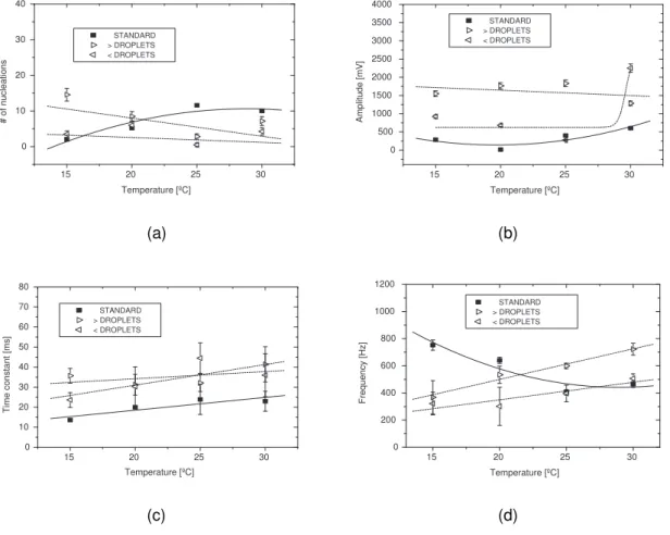
Figure 4.18: variation of signal (a) noise level, (b) event number, (c) amplitude, (d) time constant, and (e) frequency with temperature, for a CCl2F2 SDD at 1 bar pressure. ... 36
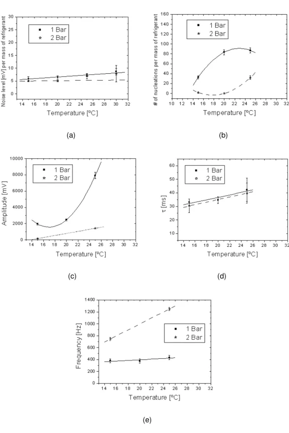
Figure 4.19: variation of signal (a) noise level, (b) event number, (c) amplitude, (d) time constant, and (e) frequency of C3F8 SDDs at 1 and 2 bar... 38
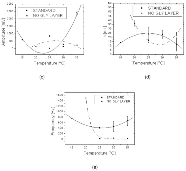
Figure 4.20: variation in signal (a) noise level, (b) event rate, (c) amplitude, (d) time constant, and (e) frequency for CCl2F2 detectors with and without the glycerin layer... 40
Figure 4.21: positioning of the microphones for the detector. ... 41
Figure 4.22: (a) Morlet based transform; (b) true nucleation signal. ... 42
Figure 4.23: experimental set-up for the measurements of the velocity of sound in gel. ... 43
Figure 4.24: velocity of a sound wave through the gel. ... 44
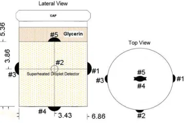
Figure 4.25: schematic of the disposition for the 5 microphones. Dimensions are in cm and # denotes the microphone number. ... 44
Figure 4.26: variation in (a) noise level and (b) signal amplitude for the 5 microphones with a standard CCl2F2 SDD as described. ... 45
Figure 4.27: variation of signal (a) time constants and (b) frequencies for the 5 microphones. ... 46
Figure 4.28: temporal evolution (pulse shape) of a typical nucleation signal, for each of the four sensors... 47
Figure 4.29: bubble nucleation map when inserting heating probes at five angular positions ( /4, 3 /4, 5 /4, 7 /4, 0) and radius 1.71 cm at depths of 0 cm to 2 cm from the device top. The microphones identify the limits. ... 48
Figure 4.30: CCD photograph of the SDD... 49
Figure 4.31: CAT scan of a SDD. ... 50
Figure 5.1: (a) output of the forced microleaks (b) zoom of one of the spikes in (a)... 52
Figure 5.2: FFT of a microleak acquired from the microphone. ... 52
Figure 5.3: signal of a fracture in the gel of a SDD. ... 53
Figure 5.4: frequency spectrum of the fracture shown in Figure 5.3. ... 53
Figure 5.6: (a) event pressure release and (b) its FFT... 54
Figure 5.7: variation in signal (a) numbers, (b) amplitudes, (c) time constants, and (d) response frequencies for detectors with different droplet size. ... 57
Figure 5.8: variation in signal (a) numbers, (b) amplitudes, (c) time constants, and (d) frequencies in terms of detector age and storage. ... 59
Figure 5.9: variation in signal (a) numbers, (b) amplitudes, (c) time constants, and (d) frequencies for the two detector concentrations... 61
Figure 5.10: variation in signal (a) numbers, (b) amplitudes, (c) time constants, and (d) frequencies for the different detector gel stiffness. ... 63
Figure 5.11: variation of refrigerant densities with temperature. ... 64
Figure 5.12: variation for the neutron recoil energy thresholds with temperature for the refrigerant (C4F10) constituents for 1 and 2 bar response. ... 65
Figure 5.13: variation for the neutron recoil energy thresholds with temperature for the refrigerant (C3F8) constituents for 1 and 2 bar response. ... 65
Figure 5.14: variation for the neutron recoil energy thresholds with temperature for the refrigerant (C4F8) constituents for 1 and 2 bar response. ... 66
Figure 5.15: (a) 1 bar amplitude nucleation response for different refrigerants; (b) 2 bar response. ... 67
Figure 5.16: (a) 1 bar time constant response for different refrigerants; (b) 2 bar response. ... 68
Figure 5.17: (a) 1 bar frequency response for different refrigerants; (b) 2 bar response... 68
Figure 5.18: (a) 1 bar number of nucleation response for different refrigerants; (b) 2 bar response... 69
Figure 6.1: variation of the recoil and αenergy thresholds with temperature for the three C2ClF5 constituents at 2.00 (solid), 2.50 (dash) and 3.00 (dash-dot) bar, with =1.40. The freon constituents are identified for 2.5 bar. The vertical line indicates the 9ºC measurement temperature; the horizontal line, a threshold recoil energy of 8 keV... 72
Figure 6.2: energy loss in C2ClF5, for a 241Am . ... 73
Figure 6.3: new nucleation efficiencies for SIMPLE with ΓSIMPLE = 4.2 ± 0.3. ... 74
Figure 6.4: comparison of the nucleation efficiencies given by Equations 6.3 and 6.4, as described in the text. ... 74
Figure 6.5: initial neutron – discrimination as reported in Ref. [103]... 76
Figure 6.6: overlay of the droplet size distribution with the observed recoil event distribution of Figure 6.5, assuming radius amplitude and with adjustments only in the numbers and location of the mean... 77
Figure 6.7: histogram of the squared amplitudes of the primary harmonic for neutron and calibration events, showing no gap between the two measurement populations... 78
Figure 6.8: histogram of the squared amplitudes of the primary harmonic for neutron and calibration events, with the thermal neutrons shielded by 2 mm of cadmium. ... 79
Figure 6.9: histogram of calibration neutron and amplitudes, large droplet distribution. ... 79
Figure 6.10: histogram of calibration neutron and amplitudes, stiffer gel. ... 80
Figure 7.1: LSBB underground galleries [60]... 83
Figure 7.2: muon flux reduction with depth... 84
Figure 7.3: components of neutron flux as a function of underground depth [91]... 85
Figure 7.4: radon monitoring (L > R) monitor, sensor installation near the water pool, monitors outside GESA... 86
Figure 7.5: DAQ system (L > R) preamplifier “core”, SDD capping & pressure transducers... 87
Figure 7.6: (L>R) cable insertion into GESA, testing of connections, completed DAQ station (outside GESA). ... 87
Figure 7.7: (L > R) SDD freon injection, SDDs being installed, and remote temperature monitoring. ... 88
Figure 7.8: SDD disposition in the 700 liter water pool... 88
Figure 7.9:signal frequency and time constant variations throughout the preliminary measurements... 90
Figure 7.10: left, signal output with the Faraday cage closed and right, opened. ... 91
Figure 7.11: (a) signal output of the Faraday cage opening and (b) its FFT. ... 92
Figure 7.12: (a) signal output car manoeuvring with door opened and (b) its FFT... 92
Figure 7.13: (a) signal output car manoeuvring with door closed and (b) its FFT... 93
Figure 7.14: signal output on knocking at the door... 93
Figure 7.15: signal output on knocking on the cable... 94
Figure 7.17: (a) signal output with human noise inside GESA and (b) its FFT. ... 95
Figure 7.18: left, signal output with the GESA closed and right, opened. ... 96
Figure 7.19: (a) signal output from water bubbles in the water tank and (b) its FFT... 96
Figure 7.20: (a) photo of the ventilation shafts and (b) a FFT of the system. ... 97
Figure 7.21: water shield (L > R) before, during, and after construction... 98
Figure 7.22: schematic view of the room and experimental set-up. 1: Detectors; 2: Tank (water below the detectors); 3: Wood support; 4: Tank pedestal; 5: Room ceiling, walls and floor; 6: Concrete floor structures defining the cable conduits; 7: Steel lining; 8: Water shield around and above the detectors; 9: Water shield around the tank pedestal... 98
Figure 7.23: model used in the MCNP simulations. (L>R) vertical front view; vertical side view, with the representation of interactions of neutrons emitted from concrete. ... 99
Figure 7.24: Stage 2 new set-up of the shielding after Stage 1 evaluation... 100
Figure 7.25: characterization of the GESA measurement site with He3 tubes. ... 100
Figure 7.26: characterization of the GESA measurement site with Bonner spheres. ... 101
Figure 8.1: organogram of the SDD identification, discrimination filter and validation analysis routines. ... 103
Figure 8.2: pressure evolution of the various SDDs on Stage 1... 105
Figure 8.3: scatter plot of the time constant of Stage 1 single event signals with respect to their frequencies. ... 105
Figure 8.4: scatter plot of the amplitude of Stage 1 single event signals with respect to their frequencies. ... 106
Figure 8.5: scatter plot of the amplitude of Stage1 single recoil signals with respect to the calibrations. ... 107
Figure 8.6: pressure evolution of the various SDDs on Stage 2... 108
Figure 8.7: scatter plot of the time constant of Stage 2 single event signals with respect to their frequencies. ... 108
Figure 8.8: scatter plot of the amplitude of Stage 2 single event signals with respect to their frequencies. ... 109
Figure 8.9: scatter plot of the amplitude of Stage 2 single recoil signals with respect to the calibrations. ... 110
Figure 8.10: various spin-dependent WIMP-proton exclusion contours for Phase II, together with the leading direct [104–106] and indirect SuperK [107], IceCube [108] search results; shown are the Stage 1 and 2 results and a merging of the two. The region outlined in grey is preferred by cMSSM [110]. ... 112
Figure 8.11: various spin-independent contours for Phase II, together with those of the leading [105, 106, 114– 121] spin-independent search results; shown are the Stage 2 result, the reanalyzed Stage 1 result, and a merging of the two. The partial contours (a) and (b) are taken from [118] and [26], respectively. The closed areas identified as either CRESST-II [122], DAMA/LIBRA [123] or CoGeNT [124] represent the regions in which possible light mass WIMPS have been respectively reported. ... 113
Figure 9.1: (L>R) evolution of gel introduction and construction of the BC prototype... 116
Figure 9.2: schematic of the acquisition, control and operating diagram circuit for the BDC. ... 116
Figure 9.3: (L>R) recompression electronics for the BDC; and the system in operation. ... 117
Figure 9.4: new piston-based recompression BDC prototype... 117
Figure 9.5: ultrasound microphone flat response over 10 – 150 kHz [130]. ... 118
Figure 9.6: new condenser microphone. ... 118
Figure 9.7: (L>R) first ultrasound recording and respective frequency spectrum. ... 119
Figure 9.8: (L>R) Freon injection, BDC coupling to piston and ultrasound microphone adjustment. ... 120
Figure 9.9: noise frequency spectrum. ... 120
Figure 9.10: (L>R) nucleation event, zoom of the event in the left. ... 121
Figure 9.11: frequency spectrum of the nucleation event seen in Figure 9.10. ... 121
Figure 9.12: (L>R) nucleation event at 4 bar, and its FFT... 122
Figure 9.13: (L>R) nucleation event at 3 bar, zoom of the event in the left. ... 122
Figure 9.14: FFT of the nucleation event seen in Figure 9.13... 123
List of Tables
_________________________________________________________________________________
Table 4.1: Acoustic spatial localization errors for different combinations of microphones... 49
Table 5.1: Comparison of true event characteristics from a CCl2F2 SDD with those of several common acoustic backgrounds. ... 55
Table 5.2: Refrigerant critical temperatures at 1 bar; Tb is the boiling temperature, Tc the critical. ... 66
Table 5.3: Refrigerant reduced superheat factor S for operation temperatures. ... 67
Table 5.4: Acoustic background events in each of the experiments (percentage of total events). ... 69
Table 6.1: Summery of results from the various calibrations... 80
Table 7.1: Installed detector and its active mass. ... 88
List of Symbols
_________________________________________________________________________________
• A - amplitude
• ap,n - effective couplings of WIMP-proton and WIMP-neutron interaction
• B - gel bulk modulus
• C - capacitance
• d - distance
•
Ω
DM - DM mass density•
ρ
(
r
)
- local halo mass density• ρV - vapour density
• LET - linear energy transfer
• Em - minimum energy required for bubble formation
• Ewall - kinetic energy imparted to the liquid by the motion of the vapour wall
• Ethr, - threshold energy, for WIMP recoils
• dR/dE - rate per unit target mass and recoil energy
• ψ - thermodynamic factor
• ε(E) - detection efficiency
• F - energy imparted to the liquid during the growth of the bubble by viscous forces
• FFT - Fast Fourier Transform
• f(v) - halo velocity distribution relative to the detector
• fp,n - effective couplings to protons and neutrons
• GF - Fermi coupling constant
• GCC - generalized cross-correlation
• h - Hubble constant
• H - vaporization energy
•
|
H
(
x
(
t
))
|
- Hilbert transform• hfg - latent heat of vaporisation
• γ(T) - surface tension of the liquid at temperature
• J - total angular momentum of the nucleus
• k - wave number
• L - length
• MACHO - Massive Astrophysical Compact Halo Object
• Mw - WIMP mass
• M(r) - mass inside the orbit
• Λ - nucleation parameter of the refrigerant
• P - pressure
• Pw - power
• PSD - Power Spectral Density
• Q - charge
• rc - critical radius
• r - radius
• S - reduced superheat
• Sp,n - expectation values for the spin content for protons and neutrons in the nucleus
• σ - zero momentum transfer cross section
• T - temperature
• Tb -boiling temperature
• Tc - critical temperature
• τ - decay time constant
• t - time
• TDOA - time delays of arrival
• v - velocity
• vgel - sound velocity in the gel
• V - Voltage
• vmin - minimum velocity an incident WIMP needs to have in order to produce a recoil of energy
• vmax - local galactic escape velocity relative to the detector (maximum WIMP velocity in the
halo)
• W - work
$%&'()
$%&'()
$%&'()
$%&'()
*')+,-.'/+*
*')+,-.'/+*
*')+,-.'/+*
*')+,-.'/+*
_________________________________________________________________________________
The composition of the Universe is one of the most challenging issues facing modern physics,
given that no understandable answer of what the Universe is made of is yet clear. Twenty three
percent of “missing” Universe is a bit too much to be left unknown. A competitive hunt is underway to
discover the composition of dark matter, a large part of which is devoted to its direct detection through
interactions with detectors in underground laboratories.
One of these direct detection experiments is SIMPLE (Superheated Instrument for Massive
ParticLe Experiments). SIMPLE is located 500 m below ground in the Laboratoire Souterrain à Bas
Bruit (LSBB) in southern France. It utilizes superheated liquid detectors and in 2005, SIMPLE
completed its Phase I, reporting results [1]from a four detector array, which – apart from setting the
benchmark in such searches for the superheated liquid technique at the time, identified several areas
requiring a significant improvement, not the least of which was its instrumentation.
The instrumentation of all superheated liquid efforts is mainly acoustic. This dissertation
describes the R&D of an advanced, microphone-based, SIMPLE acoustic instrumentation, and its
implementation in a Phase II search for evidence of a particle dark matter. The majority of the R&D
activity for the instrumentation was carried-out at Instituto Tecnológico e Nuclear (ITN), following the
SIMPLE Phase II measurements at LSBB, conducted in two Stages: Stage 1 between 27 October
2009 – 5 February 2010 and, Stage 2 between 12 April - 22 July 2010.
Chapter 2 provides a brief description of the Dark Matter scenario; Chapter 3, the
Superheated Liquid Detectors involved. The development and testing of the new acoustic
instrumentation, based at ITN near Lisbon, is presented in Chapter 4 and includes a new method for
the identification (pulse shape identification procedures) of a bubble nucleation in superheated droplet
detectors, and a description on a way of localizing the bubble nucleation in the detectors. Chapter 5
reviews observations of the SDD response using the instrumentation with regard to various production
and intrinsic noise issues. The following chapter, 6, presents the SDD sensitivities, as well as particle
discrimination through alpha and neutron calibrations.
Chapter 7 describes the implementation of the new instrumentation in Phase II of the SIMPLE
Dark Matter search experiment. The results of the search measurements are shown in Chapter 8,
Chapter 9 describes the new direction for SIMPLE based on these results, and the design and
implementation of a “Big Droplet Chamber”, in particular preliminary tests of a new high frequency
instrumentation.
The final Chapter 10 summarizes the conclusions of this thesis. In the course of the research,
many new questions emerged as the original ones were being answered: some of these ideas for
future research and development, proposals and experiments to be performed, are included.
In the course of my PhD many issues were addressed that were not part of the thesis work
$%&'()
$%&'()
$%&'()
$%&'()
%)0
%)0
%)0
%)0
%''()
%''()
%''()
%''()
_________________________________________________________________________________
2.1 Evidence of Dark Matter
The evidence of Dark Matter (DM) has been established and recognized [2,3]. The oldest
evidence for the existence of DM comes from the measurement of galactic rotation curves. The
rotational velocity v of an object on a stable orbit with radius r around a galaxy scales
as
v
(
r
)
∝
M(r)r , where M(r) is the mass inside the orbit. If the radius lies outside the visible part ofthe galaxy,
v
(
r
)
∝
1 r. In most of the observed galaxies, v tends to become constant for the largestvalues of r where the rotation curve can be determined.
The main explanation is the existence of a non-luminous halo, with mass density
2
1
)
(
r
∝
r
ρ
, at some point the mass will be proportional to the radius implying a decrease in massdensity in order to keep the total mass of the galaxy finite. This leads to a lower level on the DM mass
density,
Ω
DM≥
0
.
1
, whereΩ
X≡
ρ
X/
ρ
critical,ρ
critical being the critical mass density, so[
Ω
total=
1
] corresponds basically to a flat Universe. With the observation of such clusters of galaxiesthe tendency is to have larger values,
Ω
DM≈
0
.
2
.To date, the most accurate determination of
Ω
DMcomes from global fits of cosmologicalparameters to a variety of observations, including measurements of the anisotropy of the cosmic
microwave background (CMB) and of the spatial distribution of galaxies. The density of cold,
non-baryonic matter is found to be:
006
.
0
112
.
0
2±
=
Ω
nbmh
, (1.1)
where h is the Hubble constant.
The baryonic matter density,
001
.
0
022
.
0
2±
=
Ω
bmh
, (1.2)
may contribute to (baryonic) DM, like MACHOs [4] or gas clouds [5].
Nowadays, detailed measurements of anisotropies in the CMB radiation, galactic lenses and
comparisons of large scale structures with simulation of the structure development of the universe,
when combined into a standard cosmological model, have suggested a universe composed of 4% of
ordinary matter, 1% associated with electrons, neutrinos and photons, about 23% of DM, and 72% of
2.2 Possible Candidates
Analyses of the Universe and its structure formation indicate that most DM should be cold
(slow moving) and should have been non-relativistic during formation of the galaxy [2]. This agrees
well with the contribution of light neutrinos to Eq. (1.1),
CL
h
v
0
.
0062
95
%
2
≤
Ω
(1.3)Candidates for non-baryonic DM in Eq. (1.1) must satisfy several conditions: first, they must
be stable on cosmological time scales (otherwise they would have decayed by now or at least have a
lifetime long compared to the present age of the universe), they must interact very weakly with
electromagnetic radiation, and they must have the correct relic density. Numerous candidates have
been proposed; some of the more prominent candidates include MACHOs, axions, neutrinos,
neutralinos and weakly interacting massive particles (WIMPs).
These candidates in principle will be detectable with present or near-future technology. But
there are also particle physics DM candidates which currently seem almost impossible to detect,
unless they decay. These include the gravitino and the axino, to give two examples.
2.2.1 MACHOs
One of the simplest candidates for dark matter is a Massive Astrophysical Compact Halo
Object (MACHO). MACHOs are objects that not directly observed, are made of ordinary matter. These
could be compact objects such as cold white dwarfs or black holes. Astronomical searches have found
such objects through microlensing, but the total amount of these objects is not enough to make up all
of the missing matter [5].
2.2.2 Neutrinos
An experimentally verified dark matter candidate is the neutrino [2,5]. Neutrinos have been
considered excellent dark matter candidates because it is proved that neutrinos have small but
non-zero masses by neutrino oscillation detection, as seen from Eq. (1.3). However, neutrinos are
relativistic particles which large scale structure constrains to make up only a few percent of the total
non-ordinary dark matter. Hence, neutrinos cannot be a major constituent of the halo dark matter.
2.2.3 Axions
These hypothetical light pseudo-scalar particles have often been discussed as DM
candidates. Laboratory experiments [6] limit axions to be very light (taking account all recognized
uncertainties one arrives at a plausible range for the mass of dark-matter axions between a few eV
extremely long lifetime (many orders of magnitude larger than the age of the Universe). Axions that
would have been produced in the Big Bang were never in thermal equilibrium and were always
non-relativistic (i.e. they are “cold” Dark Matter). The calculation of axion relic density depends on the assumption made regarding the production mechanism. Nevertheless it is possible to find in the range
mentioned above, where axions satisfy all present constraints to represent a possible Dark Matter
candidate.
2.2.4 Neutralinos
The Neutralino is a high-quality dark matter candidate in the framework of the Supersymmetry
theory.
Supersymmetry (SUSY) was proposed as an expansion of the particle physics standard
model to combine the four fundamental forces of nature (electromagnetic, weak, strong and
gravitational). Each standard model particle has a superpartner in SUSY, which differ by half a unit of
spin. The neutralino is the lightest Supersymmetric particles (LSP), which is stable in SUSY models
where R parity (R-parity conservation implies that LSP cannot decay) is conserved.
There is a large parameter space left to be probed by current technologies. The Neutralino is
one the most well-liked dark matter candidates that is explored by on-going direct detection
experiments via its elastic scattering from a nucleon of the detector material. Indirect Neutralino
searches, via their annihilation products, such as high energy neutrinos, antiprotons, positrons and
gamma rays are also pursued.
Although particle physics experiments place some constrains on the SUSY parameter space,
a clear signal from a laboratory discovery of a dark matter particle will significantly constrain the
mechanisms, the calculation of the relic density and the Neutralino candidates in the MSSM (Minimal
Supersymmetric Model).
The lightest Supersymmetric particle (LSP) can be referred in the context of cold dark matter
as a WIMP, or Weakly Interacting Massive Particle, which refers to a general class of unidentified
particles postulated by Supersymmetry. By definition, they interact only via the weak interaction and
gravity.
2.2.5 WIMPs
WIMPs are particles with mass roughly between a few GeV and a few TeV, and with weak
cross sections of approximately the same strength.
The WIMP mean velocity is expected to be a few hundred kms-1. As such, WIMPs interact
with ordinary matter through elastic scattering on nuclei and so with the expected WIMP masses
Hence, the expected interaction rate depends on two quantities: the mass and cross section of the
WIMP. The cross section depends on the nature of the couplings.
The calculated event rates are lower than common radioactive backgrounds, on the order of
<< 1 event per kilogram of detector per day. This implies the need for additional protection against
induce cosmic rays backgrounds, thus all projects "hide" themselves in underground laboratories. The
sensitivity (of any detector) is best for WIMP masses near the mass of the recoiling nucleus.
2.3 Dark Matter Detection
The interaction of a WIMP with the detector material can be either elastic or inelastic, and
either spin-dependent or spin-independent.
• Elastic and inelastic scattering: Elastic scattering involves the interaction of a WIMP with the
nucleus as a whole, causing the nucleus to recoil. In inelastic scattering all of the energy does
not go into nuclear recoil; instead the nucleus is excited to a higher energy state which then
decays by photon emission.
• Spin-dependent and spin-independent scattering: Spin-dependent (axial-vector) scattering
results from the coupling of a WIMP's spin with the spin of a nucleon. Spin-independent
(scalar) does not depend on spin, and has the advantage of higher cross sections with larger
nuclei (because of coherence where the WIMP interacts with the nucleus as a whole, scaling
as A2).
Energy lost by a recoiling nucleus is converted to electrons, photons, phonons, and ion pairs.
The detection of DM can be summarized in three forms:
• Phonon/Thermal: A vibration (detected as a rise in temperature) in the crystal lattice of the
detector, caused by the slight movement of a nucleus which has recoiled. An extremely
sensitive temperature system is located around the detector, allowing any temperature
variation to be recorded.
• Ionization: A recoil nucleus gives an electron in the detector enough energy to escape its
nucleus. A small electric field is set up in the detector to push the new charge to a detector
wall where it can be registered as an ionization event.
• Scintillation: Occurs when an electron absorbs enough energy from a recoil event to reach to
a higher energy state. After a short time, the electron will lose this energy by emitting a
photon, which is then recorded by photomultipliers and converted to an electric signal for
2.3.1 Direct Detection
The majority of present experiments use these detector technologies:
- Scintillation: (DAMA/LIBRA[7], KIMS[8])
- Cryogenic: (CDMS[9], EDELWEISS [10], CRESST[11])
- Ionization: (CoGeNT[12])
- Noble Liquids: (XENON[13], ZEPLIN[14])
- Superheated Liquids: (COUPP[15], PICASSO[16], SIMPLE[17])
In general detecting only one of these channels is insufficient for particle discrimination.
Hence, the majority of experiments use the detection of two of these channels permitting a
discrimination between recoil and background particle interaction.
The DAMA collaboration has reported results from a total of 6 years exposure, with its new
phase called LIBRA involving 250 kg of detectors. With addition of their earlier exposure of the original
DAMA/NaI experiment with 100 kg of detectors [18], the total exposure sums up to 1.17 ton.year. They
observe an annual modulation of the signal in the 2 to 6 keVee bin,), at 8.9 sigma level. If interpreted
within the standard halo model, a couple of possible explanations have been considered: a WIMP with
mχ∼ 50 GeV and σχρ∼ 7 · 10
−6
pb, or at low WIMP mass region, between 6 to 10 GeV with σχρ∼ 10
−3
pb.
The KIMS Collaboration [8], is an experiment operating 12 crystals of CsI(Tl) with a total mass
of 104.4 kg in the Yang Yang laboratory in Korea. It has been running several years of continuous
operation and data acquisition. They should soon be able to confirm or not the DAMA value at 3
sigma. They have recently presented a new result at TAUP 2011 [19].
At low temperature in the orders of mK, the simultaneous measurement of the ionization and
phonon signals in semiconductor detectors permits event discrimination between nuclear and
electronic recoils down to 5 to 10 keV recoil energy.
At the Soudan Underground Laboratory, the CoGeNT collaboration [12] has operated a 440 g
Germanium detector with an effective threshold of 400 eV for ~60 days [20]. After analysing the
physics data and removing the surface interactions known from incomplete charge events, the result
was an excess of events from the spectrum below 4 keV, agreeable with a low mass WIMP in the
range of 7 to 11 GeV, and a cross section around 10−4 pb.
CDMS, after operating 19 Germanium cryogenic detectors at the Soudan mine with a total
exposure of ~ 600 kg.d (~ 300 kg.d fiducial) [21] presented two events in the defined signal region,
while only 0.9 background events were expected. No observation of a signal was claimed. The
combined data from this run and previous provided an improved upper limit on the spin-independent
EDELWEISS has operated for one year ten Germanium detectors with 400 g each and are
equipped with different thermal sensors, at the Laboratoire Souterrain de Modane [22]. A total of 5
events were observed in the signal region for a fiducial exposure of 384 kg.d, while 3 events were
expected from backgrounds. No WIMP signal was claimed.
Having similar sensitivities, CDMS and EDELWEISS combined their data sets. This merging resulted
in a gain of 1.6 relative to the best limit for WIMPs at masses larger than 700 GeV, and an improved
limit of 3.3×10⁻⁸ pb for a 90 GeV WIMP mass [23].
The cryogenic experiment CRESST uses the scintillation of CaWO4 as second variable for
background discrimination. CRESST has recently presented a result [24] of the analysis of 730 kg.day
exposure performed with 8 detectors. The observation of 67 events in the signal region is above the
40 expected background events. The event excess has been considered compatible with WIMPs.
The XENON collaboration [13] has operated the 161 kg XENON100 setup at Gran Sasso
laboratory during a 100 day data acquiring. This resulted in a fiducial mass of 48 kg, originating 3
events observed in the signal region, while only 1.8 were expected, out of which 1.2 originate from
contamination of Krypton 85 in the liquid [25]. This has allowed to set the best limits at all masses on
spin-independent interactions of WIMPs, with a minimum of cross section at 7.0×10⁻⁹ pb for a mass of
50 GeV.
ZEPLIN III [26], with an active mass of 12 kg of Xenon, operated in the Boulby mine, was
upgraded for a lower background, acquiring new data, and is now unfortunately finished. It delivered
competitive limits and pioneered the use of a high electric fields to improve the electron-nuclear recoil
discrimination.
The detectors using 19F nuclei setting limits mainly on the spin dependent sector of WIMPs
are: the bubble chamber like detector, from COUPP [15], that provided a new limit [27] for spin
dependent proton coupling WIMPs for masses above 20 GeV, PICASSO [16], a superheated droplet
detector run at SNOLAB, obtained a better limit below 20 GeV on the same type of WIMPs [28], and
SIMPLE [17], running in France at the Laboratoire Souterrain à Bas Bruit, that has provided the
currently best limit on the spin-dependent WIMP-proton cross section for all WIMP masses [29].
There is also the possibility of dark matter production in accelerators. Producing and detecting
dark matter particles in an accelerator would be a huge step toward confirming the existence of dark
matter, although direct detection has to be confirmed. Attempts in the near future should confirm if this
is feasible or not.
2.3.2 Indirect Detection
WIMPs are capable of annihilation, and their products: neutrinos, gamma rays, positrons, etc,
can be detected. Indirect measurements complement the direct detections, and are able to reach
higher masses and different coupling interactions.
WIMPs can be slowed down, captured, and can stay in celestial objects such as planets or
neutrinos which can interact in the Earth. These muons can then be detected in large neutrino
telescopes such as, SuperKamiokande [30], AMANDA [31], ANTARES [32], and the large sensitive
area of IceCube [33]. The best limit comes from muons with energy above ~2 GeV from
SuperKamiokande. For slightly more energetic muons, the most stringent limit has been set by
IceCube.
2.4 Challenges of Direct Dark Matter Searches
There are several difficulties associated with dark matter search experiments:
• Logistics.
• Radioactive contamination from the detector itself.
• The cross section is very small: <10-6 pb, implying the need for large mass, sensitive detector
material.
• The expected recoil energy of nucleus is also very small: 10 ~ 100 keV.
• The background rate due to neutrons, alpha-particles, gamma-rays, cosmic-rays, etc is much
larger than the expected WIMP rate. This implies the need for an underground laboratory and
careful selection of shielding and detector material and particle discrimination by the detector
in an event-by-event basis.
Direct detection experiments typically operate in deep underground laboratories to reduce the
background from cosmic rays. These include: the Laboratoire Souterrain a Bas Bruit, Rustrel (France);
the Soudan mine (USA); the SNOLAB underground laboratory at Sudbury, Ontario (Canada); the
Gran Sasso National Laboratory (Italy); the Boulby Underground Laboratory (UK); and the Deep
$%&'()
$%&'()
$%&'()
$%&'()
-&()$(%'(,
-&()$(%'(, /1-/,2
-&()$(%'(,
-&()$(%'(,
/1-/,2
/1-/,2
/1-/,2
_________________________________________________________________________________
3.1 Scope
The SIMPLE experiment is based on the use of superheated liquids, mainly Superheated
Droplet Detectors (SDDs), in which an interaction of radiation generates the phase transition of a
superheated liquid droplet, producing a detectable bubble.
A fluid is superheated when it is in liquid form at temperature and pressure values
corresponding to the vapour region in its phase diagram. This metastable state is fragile and
short-lived due to the high number of microscopic particles and/or gas pockets normally present at the
interface with container surfaces. These act as seeds for the phase transitions and are called
“heterogeneous” nucleation sites.
In order to achieve a steady state, the liquid must be moderately superheated, i.e., possess a
relatively small difference between its operating temperature and boiling point. Halocarbons with a
moderate degree of superheating can be used for particle detection since they are nucleated by
energetic heavy ions, such as those produced by fast neutrons [34]. Halocarbons operated near their
boiling point can be used in the detection of minimum ionising radiations, such as photons and
electrons [35,36].
Two types of detectors utilize this technique; the Superheated Droplet Detector (SDD) and the
Bubble Chamber (BC).
3.2 Superheated Liquid Physics
Radiation-induced nucleation is explained within the framework of the Seitz “thermal spike”
model [37], which states that when a heavy charged particle slows down in moving through a liquid,
kinetic energy is transferred as thermal energy to extremely small regions (as temperature spikes).
The intense heating induces localized boiling, creating trails of sub microscopic vapour seeds of
different sizes. Only a vapour seed which reaches critical size will grow into a macroscopic observable
vapour bubble. Although the process is extremely complex, involving aspects of atomic and nuclear
physics as well as fluid thermodynamics, in Seitz’s approach these are avoided under the assumption
of a static, equilibrium phase transition of the superheated fluid.
Following the Seitz’s model, the minimum work (W) required to create a spherical bubble of
P
r
T
r
W
=
2−
3∆
3
4
)
(
4
π
γ
π
,
(3.1)where γ(T) is the surface tension of the liquid at temperature T; ∆P is the difference between the
equilibrium vapour pressure and the externally applied pressure.
The minimum work increases with the size of the bubble, reaching a maximum and then
decreasing. The maximum constitutes an energy barrier, which must be overcome in order for bubble
nucleation to occur. The bubble radius corresponding to this maximum is called the critical radius (rc)
and is given by:
P
T
r
c∆
=
2
γ
(
)
,
(3.2)Substituting equation (3.2) into equation (3.1) the minimum reversible work needed to form a critical
size bubble is then:
(
)
∆
=
2 3)
(
)
(
3
16
P
T
W
π
γ
.
(3.3)
This equation implies that as the temperature increases, W decreases and less energy is required for
vapour nucleation. When dissipative forces are considered (viscosity, etc.), the minimum energy Em
required for bubble formation is given by [39]:
F
E
H
W
E
m=
+
+
wall+
,
(3.4)where H is the vaporization energy, Ewall is the kinetic energy imparted to the liquid by the motion of
the vapour wall and F is the energy imparted to the liquid during the growth of the bubble by viscous
forces. H is given by:
3
4
,
3
c v fgH
=
π
r
ρ
h
(3.5)where ρV is the vapour density and hfg the latent heat of vaporisation.
Radiation-induced thermodynamics is a dynamic process involving the fluid thermodynamics
of the growth of the bubble. This is not included in the static equilibrium thermodynamic approach and
therefore the Seitz model does not provide a complete description. An attempt at a complete
dynamical model for bubble nucleation in a superheated liquid by ionising radiation was proposed
using a numerical technique [40]. However, the required amount of computational time prohibits its
general use; models [41] and even semi-empirical approaches [42] to understand the mechanism are
used for practical purposes.
In the case of neutrons, the energy deposition occurs through the secondary ionising particles
produced during interaction with the nuclei of the liquid. When a neutron of energy En interacts with a
nucleus of atomic weight A, the maximum kinetic energy that can be transferred to the nucleus from
the neutron is through an elastic head-on collision and is given by:
n A
E
A
A
E
2)
1
(
4
+
=
.
(3.6)∆
+
=
P
h
W
E
c1
ρ
v fg.
(3.7)
After receiving the energy, the nucleus is scattered and moves through the liquid losing its
energy via Coulombic interactions until it comes to rest. For a given neutron energy, different nuclei of
the liquid will receive different amounts of energy, depending on their atomic weight. The ion with the
highest value of linear energy transfer (LET) or (dE/dx) in the liquid will play the major role in vapour
nucleation. The energy deposited by the charged particle within a distance L along the radiation
particle track, Ec, must be larger than the energy required for bubble formation and is given by:
Λ
=
=
dx
dE
r
dx
dE
L
E
c c.
(3.8)
Equation (3.8) associates the length L with the critical bubble radius by a numerical constant . Hence,
the nucleation requirement is satisfied if:
Λ
=
Λ
≥
c cr
W
r
Ec
dx
dE
ψ
.
(3.9)By considering that the energy deposited along that part of the ion’s range corresponding to twice the
critical radius contributes significantly to bubble formation, Apfel et al. [41] found that the Gibbs energy
W, given by equation (3.3), corresponds to only 3-5% of the energy deposited in the critical diameter
Ec=2rc(dE/dx).
The thermodynamic factor ψ=W/Ec (accounts for the conversion efficiency of heat to work) has
been utilized to calculate the threshold neutron energy for a given liquid and temperature [41].
Because of the differing thermodynamic properties of the various available refrigerants employed in
SDD fabrications, their response characteristics differ both with temperature and pressure. Recently
[42], it has been observed that by introducing a non-dimensional quantity, “reduced superheat”,
defined as:
)
(
)
(
b c bT
T
T
T
S
−
−
=
,
(3.8)where Tb and Tc are the boiling and critical temperatures of the liquid, respectively, the device
responses all occur on a “universal” curve. For example, operated at S ≤ 0.5, the SDD is insensitive to
electrons, muons, gammas and other minimum-ionizing radiation, independent of its refrigerant basis
(although this threshold occurs at different temperatures for different refrigerants). This indicates that
the SDDs in particular thermodynamic conditions are capable of a self-background reduction.
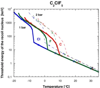
The response of a detector depends both on its operating temperature and pressure. Figure
3.1 shows a simulation of the recoil energy threshold of each nucleus with increasing temperature for
a C2ClF5 (R-115) SDD, at 1 and 2 bar [58,59]. At 2 bar, the device must be operated at a higher
temperature or else the recoil energy of the nucleus (F, C and Cl) lower than 250 keV, will not allow
detection of events up to 35ºC, because the temperature equivalent to the threshold energy of each
recoil nucleus (F and C) is shifted to near the sol–gel transition temperature at which the gel is liquid.
The threshold neutron energy-temperature relation given in Figure 3.1 can be adopted to convert the
interval it should elicit a response. The nucleation parameter used was = 1.4 from reference [79],
instead of the approximated value (2) for the majority of liquid refrigerants [41]. The results are in good
agreement with the thermodynamic calculations and confirm the energy response as a function of
temperature. 0,1 1 10 100 1000 104
-20 -10 0 10 20 30
C2ClF5
T h re s h o ld e n e rg y o f th e r e c o il n u c le u s [k e V ] Temperature [°C] 1 bar C Cl F 2 bar
Figure 3.1: variation in threshold energy of the recoil nucleus with temperature for a C2ClF5 SDD at 1 and 2 bar.
3.3 Applications of Superheated Liquid Detectors
Superheated liquid detectors are used as dosimeters for neutrons because of their unique
sensitivity response [43], which was in fact the origin of their introduction [44]. They have more
recently been used in heavy-ion detection [45], and also in the direct search for particle dark matter
[1,46].
3.3.1 Neutron Dosimetry and Spectrometry
SDDs have been pursued for applications in neutron dosimetry [43,44] and spectrometry
[47,48,49] for almost two decades. They have been shown to comply with ICRP 60 recommendations
for accuracy of measurement, real-time response, low minimum detection threshold and, most
importantly, a nearly dose equivalent response [50].
More recent developments include position-sensitive neutron spectrometers/dosimeters for
application in radiotherapy [51], in energy and angle-differential neutron fluence measurements [52],
and in response enhancement to high energy neutrons [53]. In fact, the differential angle and energy
double distributions of the fluence constitute the most complete description of a neutron field. The
(kerma, absorbed dose) and non-isotropic protection quantities (organ doses, effective dose) or
operational quantities (personal dose equivalent, directional dose equivalent).
3.3.2 Heavy-ion Detection
SDDs have been demonstrated to be good detectors for registration of high and intermediate
energy heavy ions [54]. The ion tracks are visible by the naked eye and can be stored for months or
years without losing their sensitivity. These detectors are also a type of threshold detector for
identifying heavy ions. Based on these properties, bubble detectors are expected to have applications
in heavy ion physics, cosmic ray physics, exotic particle detection and imaging of cancer therapy
[55,56].
3.3.3 Dark Matter Searches
WIMPs are theoretically similar to that of elastic scattering slow neutrons. The fact that their
interaction is weak implies that the event rates are extremely low – sufficiently so in fact as to be
masked by common low-level radioactive backgrounds (such as cosmic rays, electrons and gamma
rays) unless the search experiments are constructed of radio-pure materials and conducted deep
underground. The insensitivity of the superheated liquid technique to the majority of these background
complications is the driving force behind their application in this area.
SIMPLE (Superheated Instrument for Massive Particle Experiments) is one of only two
experiments to search for evidence of spin dependent WIMPs using C2ClF5-based SDDs [17], the
other being PICASSO using C4F10 [16]. Given the weakness of the interaction, and that the rate scales
with target mass, significant efforts have been made to increase the refrigerant concentration,
resulting in 1-2% active mass devices (v-a-v their 0.1% dosimetry progenitors).
COUPP, although using the same technique, is based on a CF3I bubble chamber [15].
3.4 Superheated Droplet Detectors
Superheated Droplet Detectors (SDDs) are a type of “superheated emulsion”, which is the
denomination adopted by the International Commission on Radiation Units and Measurements (ICRU)
and International Organization for Standardization (ISO) for detectors consisting of uniform
dispersions of superheated halocarbon droplets suspended in a compliant material such as a
polymeric or aqueous gel [57].
Each droplet in the emulsion behaves like a bubble chamber. However, the liquid must be
fractionated into droplets and dispersed in an immiscible host fluid, a process called emulsification.
This procedure creates perfectly smooth spherical surfaces, free of nucleating impurities or
irregularities. The emulsifier material must be clean and de-gassed, i.e., free of heterogeneous
nucleation sites. Number, size and composition of the droplets can be varied in the fabrication of the
3.4.1 SDD Fabrication
Protocols for detector fabrication are widespread and well developed [128]. Generally, these
involve the use of polyacrylamide-based gels, with the addition of heavy element salts (which
introduces radio-impurities) in order to density-match the gel with the refrigerant towards the
production of a homogeneous droplet distribution. SIMPLE in contrast relies exclusively on the use of
food-based gels, and viscosity-matching where necessary.
All fabrications generally involve three essential phases:
1. The fabrication of the gel;
2. The gel outgassing; that removes air bubbles trapped in the gel during the fabrication;
3. The suspension fabrication, in which the liquid is homogeneously dispersed in the gel in the
form of micrometric droplets.
In the SIMPLE project, the SDDs are fabricated in-house [58] from C2ClF5 (R-115) with a 1-2%
loading. The refrigerant is selected because of its low solubility (reducing the probability of unchecked
bubble growth by permeation) and large molecular size. Liquid droplets (radius 5–150 µm) are
fractionated by rapid stirring and dispersed in an elastic, viscous gel as shown in Figure 3.2.
Figure 3.2: droplet microscopic picture.
A homogeneous droplet suspension is produced by adjusting the gel composition in order to obtain a
uniform density, equal to that of liquid freon. The resulting mixture is out-gassed and maintained
above its gelatine temperature before placing it in a hyperbaric chamber. The pressure is raised well
above the freon vapour pressure to avoid boiling during the vigorous stirring that follows. After a
uniform droplet dispersion has been obtained, cooling, setting and stepwise adiabatic decompression
0 10 20 30 40 50 60 70
0 5 10 15 20 25 30
T
e
m
p
e
ra
tu
re
[
°C
]
Pressure [bar]
SDD
Figure 3.3: simultaneous creation of two metastable systems.
Some important precautions are strictly necessary for producing stable modules. For example,
the stepwise decompression procedure used is identical to that employed by scuba divers returning to
the surface, in order to minimize the cavitations of dissolved gas bubbles which, in SDDs, can act as
inhomogeneous nucleation centers. In general, the size distribution of the droplets depends on the
amount and speed of the stirring. As Figure 3.4 shows, the droplet size can vary from 5 to 150 µm in
diameter [59].
Figure 3.4: diameter size distribution within the SDDs [79].
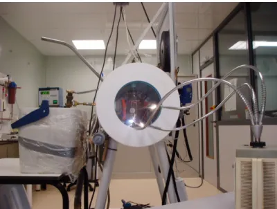
The fabrication of a SDD detector takes approximately two days. Figure 3.5 shows one of the
fabrication facilities, with its pressure chamber and accompanying pressure control, the temperature