3D
M
ODELLING OF
S
HEET
P
ILE
C
ORNER IN
D
IFFICULT
G
ROUND
C
ONDITIONS
J
OSÉB
ENEDITOG
ONÇALVESA
RÊDEC
ALEJODissertação submetida para satisfação parcial dos requisitos do grau de
MESTRE EM ENGENHARIA CIVIL —ESPECIALIZAÇÃO EM GEOTECNIA
Orientador: Professor Doutor António Milton Topa Gomes
Tel. +351-22-508 1901 Fax +351-22-508 1446 [email protected]
Editado por
FACULDADE DE ENGENHARIA DA UNIVERSIDADE DO PORTO Rua Dr. Roberto Frias
4200-465 PORTO Portugal Tel. +351-22-508 1400 Fax +351-22-508 1440 [email protected] http://www.fe.up.pt
Reproduções parciais deste documento serão autorizadas na condição que seja mencionado o Autor e feita referência a Mestrado Integrado em Engenharia Civil - 2014/2015 - Departamento de Engenharia Civil, Faculdade de Engenharia da Universidade do Porto, Porto, Portugal, 2015.
As opiniões e informações incluídas neste documento representam unicamente o ponto de vista do respetivo Autor, não podendo o Editor aceitar qualquer responsabilidade legal ou outra em relação a erros ou omissões que possam existir.
Este documento foi produzido a partir de versão eletrónica fornecida pelo respetivo Autor.
Aos meus pais, irmãs, amigos e avô
ACKNOWLEDGMENTS
This project is the climax of an unforgettable phase of my life that defined me as a civil engineer and as a citizen of the world. During the five years of my degree, and especially in the last 4 months, I had the support from many people, to whom I would like to express my gratitude:
To my supervisor in Portugal, Professor António Topa Gomes, for all the recommendations, guidance, motivation and feedback;
To my supervisor at COWI, Professor Ole Hededal, for the theoretical support, recommendations and especially for providing me this amazing opportunity of developing my thesis in such a recognized company;
To all the staff of COWI, who provided me with the necessary knowledge to conclude my project successfully and also for the advice given to thrive in the engineering world;
To António Fonseca, for the companionship and laugh in every day we spent together at COWI, and for all the critics, suggestions and discussion of the problems I was facing day by day;
To Diana Abrunhosa, for being an awesome adventure partner, keeping me inspired and motivated to accomplish my objectives as an engineer and as a person;
To my dearest friend João Nogueira, for being my University companion and, for sure, a friend for life;
To all the people that shared with me these 5 years of knowledge gain, personal development and increase of life profit;
ABSTRACT
Anchored sheet piles are used as perimeter bunds for a reclamation area. Example of such use is the Värtahamnen Port, in Stockholm. In this case, soil conditions are relatively poor consisting of soft clay/sediments overlaying a thin layer of till and, under that, very competent bedrock. The soft sediments are improved by means of either lime-cement columns or rigid inclusions consisting of grout piles installed by high-pressure jetting.
A key element in the design is the corner layout where the sheet piles are mutually supporting each other by ties instead of anchor plates. The backfilling construction method, the complex ground conditions and the kinematics of the retaining system are difficult to analyse analytically or by simple design methods. Hence, a three dimensional finite element method model is developed using PLAXIS 3D to investigate the performance of the corner in terms of global deformations and stability, earth pressure distribution as well as forces in structural elements.
The author opted to focus on three scenarios related to different conditions of soil reinforcement (by jet grouting or lime-cement piles) to study changes in wall behaviour and global stability.
Results obtained are according to expected. The application of soil reinforcement reduces earth pressures acting on the wall. Moreover, soil reinforcement reduces maximum deformations of the retaining wall and maximum structural forces. Jet grouting reveals to be a conservative and necessary solution for the stability of the sheet pile wall. Also, a sensitivity analysis to evaluate the influence of surface roughness of the sheet pile wall is provided.
KEYWORDS: multi-anchored sheet pile wall, soil improvement, lime-cement piles, jet grouting, numerical analysis, finite element method, mutually supported corner, backfilling.
RESUMO
Cortinas de estaca-prancha são usadas como paredes de retenção para efeitos de reclamação de terreno. Um caso tipo é o porto Värtahamnen, em Estocolmo. Nesta situação, as condições do solo são fracas consistindo numa camada de argila mole normalmente consolidada (sedimentos) sobre uma fina camada competente de till (depósitos glaciares), sob a qual está presente uma camada bastante competente de maciço rochoso. A camada de sedimentos é reforçada tanto por colunas de cal-cimento ou blocos rígidos constituídos por estacas instaladas via jet grouting a alta pressão.
Um elemento chave no dimensionamento é a forma do canto onde as cortinas de estaca-prancha se suportam mutuamente por tirantes em vez de ancoragens de placa. O método construtivo por enchimento, as complexas condições do solo e a cinemática do sistema de retenção tornam-se de difícil análise pela via analítica ou métodos simples de dimensionamento. Assim, na presente dissertação é desenvolvido um modelo tri-dimensional pelo método dos elementos finitos usando o PLAXIS 3D para investigar a performance do canto em termos de deformações e estabilidade global, distribuição de pressões de terras assim como os esforços nos elementos estruturais.
O autor optou por se focar em três cenários relacionados com diferentes condições de melhoramento do solo (jet grouting ou colunas de cal-cimento) de modo a estudar alterações no comportamento da estrutura e estabilidade global.
Os resultados obtidos são de acordo com esperado. A aplicação de técnicas de reforço do solo reduz as pressões de terra a atuar na cortina. Além disso, o solo reforçado reduz as deformações máximas da cortina e os máximos esforços na estrutura. A aplicação de jet grouting revelou ser uma solução conservadora e necessária para a estabilidade da cortina. Na presente tese é também apresentada uma análise de sensibilidade para avaliar a influência da rugosidade da cortina metálica.
PALAVRAS-CHAVE: cortinas estaca-prancha pluri-ancoradas, melhoramento de solo, colunas de cal-cimento, Jet Grouting, análise número, método elementos finitos, canto com suporte mútuo, enchimento.
ABSTRAKT
Forankrede spunsvægge bliver ofte brugt som afgrænsning for en arealudnyttelse. Et eksempel på en sådan situation er Värtahammen i Stockholm. I dette tilfælde er jordforholdene relativt dårlige, bestående af bløde sedimenter og ler, lejret på et tyndt lag af moræne ler, hvor under der er solidt fjeld. De bløde sedimenter er blevet forstærket enten gennem brugen af kalk-cement søjler eller injicering bestående af cementpæle installeret ved højtryksinjicering.
Et væsentligt element i designet er hjørnesamlingen, hvor spunsvæggene støtter hinanden gennem trækbjælker i stedet for ankerplader. Påfyldningsprocessen, de besværlige jord forhold og kinematikken i støttesystemet gør en analytisk analyse eller simpel design metode besværlig. Derfor er en tredimensionel finite element model udviklet i PLAXIS 3D til at undersøge opførslen i hjørnesamlingen i forhold til globale deformationer, stabilitet, jordtryksfordeling og kræfterne i strukturelle elementer.
Forfatteren har valgt at fokusere på tre scenarier relateret til forskellige jordforstærkningsforhold (trykcementering eller kalk-cement pæle) for at studere ændringerne i vægopførsel og den globale stabilitet.
De opnåede resultater er som forventede. Brugen af jordforstærkninger reducerer jordtrykket på væggen. Derudover reducerer jordforstærkninger de maksimale deformationer i støttevæggen samt de maksimale strukturelle kræfter. Trykcementering viser sig at være en konservativ og nødvendig løsning for stabiliteten i spunsvæggen. Desuden er en sensitivitets analyse til at vurdere indflydelsen af overfladerughed på spunsvæggene udført.
NØGLEORD: multipelt forankrede spunsvægge, jordforstærkning, kalk-cement søjler, trykcementering, numerisk analyse, finite element method, gensidigt støttet hjørne, fyld.
TABLEOFCONTENTS ACKNOWLEDGEMENTS... i ABSTRACT ... iii RESUMO ... v ABSTRAKT ... vii
1. INTRODUCTION ... 1
1.1.BACKGROUND ... 1 1.2.OBJECTIVES ... 2 1.3.STRUCTURE OF THESIS ... 22. CASE STUDY: ANCHORED SHEET PILE CORNER ... 3
2.1.INSPIRATION:STOCKHOLM PORT ... 3
2.1.1.PROJECT BACKGROUND ... 3
2.1.2.CONSTRUCTION PROCEDURE ... 4
2.1.3.BACKFILLED MUTUALLY SUPPORTED SHEET PILE CORNER ... 5
2.1.3.1. Corner Effects ... 7
2.1.3.2. Corner Tie Rods ... 9
2.1.3.3. Failure Mechanisms ...11 2.1.3.4. Soil Reinforcement ...11 2.2.GROUND CONDITIONS ... 13 2.2.1.CLAYEY SEABED ...13 2.2.2.GLACIAL TILL...13 2.3.BACKFILL CONDITIONS ... 14 2.3.1.CONSIDERATIONS IN BACKFILLING ...14 2.3.2.BACKFILL MATERIAL ...14
2.4.ELEMENTS OF ANCHORED SHEET PILE WALL... 15
2.4.1.SHEET PILE WALL ...15
2.4.2.ANCHOR RODS ...18
2.4.3."DEADMAN"ANCHOR ...19
2.4.4.WALING AND CAPPING BEAM ...22
2.5.2.JET GROUTING PILES ... 25
3. ANALYTICAL ANALYSIS ... 29
3.1.INTRODUCTION TO ANALYTICAL ANALYSIS ... 29
3.2.TERZAGHI &PECK DIAGRAMS ... 29
3.3.EQUIVALENT TIE SUPPORT METHOD ... 30
3.3.1.CLASSICAL DESIGN METHODS ... 30
3.3.2.EQUIVALENT TIE SUPPORT METHOD PROCEDURES ... 31
3.4.SUB-GRADE REACTION METHOD ... 33
3.5.STABILITY ANALYSIS OF SHEET PILE WALL... 34
3.5.1.LATERAL EARTH PRESSURES CALCULATION ... 34
3.5.2.SOIL CHARACTERISTICS ... 36
3.5.3.SHEET PILE WALL SYSTEM ... 38
3.5.3.ANALYSIS OF THE RESULTS ... 39
4. THREE-DIMENSIONAL MODELLING IN PLAXIS 3D ... 45
4.1. NUMERICAL ANALYSIS ... 45
4.1.1.3DANALYSIS ... 45
4.1.2.FINITE ELEMENT METHOD ... 46
4.1.3.PLAXIS3D ... 46 4.2.INPUT INFORMATION... 47 4.2.1.SOIL LAYERS... 47 4.2.2.GEOMETRY ... 49 4.2.3.STUDY SCENARIOS ... 51 4.2.4.BOUNDARY CONDITIONS... 54
4.2.5.SOIL MODELS AND PARAMETERS... 56
4.2.6.STRUCTURES AND INTERFACES ... 58
4.2.7.LOADING AND STAGES OF CONSTRUCTION ... 60
5. ANALYSIS OF RESULTS ... 63
5.1.METHODOLOGY ... 63
5.1.1.CROSS SECTIONS ... 63
5.1.2.EXTRACTION OF EARTH PRESSURES ... 64
5.2.VERIFICATION OF THREE DIMENSIONAL EFFECTS ... 65
5.3.NO SOIL REINFORCEMENT (NR) ... 67
5.3.2.WALL DEFORMATION MODE ...71
5.3.3.DEFORMATION OF CORNER ...74
5.3.4.STRUCTURAL FORCES ...77
5.3.4.1 Anchors and Ties ...77
5.3.4.2 Waling and Capping Beam ...78
5.3.4.3 Sheet Pile Wall ...80
5.4.KCPILES (KC) ... 83
5.4.1.EARTH PRESSURE ...83
5.4.1.1 Coefficient of Earth Pressure ...83
5.4.1.2 Transfer of Loads through the Monolith ...86
5.4.2.WALL DEFORMATION MODE ...87
5.4.3.DEFORMATION OF CORNER ...89
5.4.4.STRUCTURAL FORCES ...91
5.4.4.1 Anchors and Ties ...91
5.4.4.2 Waling and Capping Beam ...91
5.4.4.3 Sheet Pile Wall ...93
5.5.KCPILES AND JET GROUTING (KC&JG) ... 96
5.5.1.EARTH PRESSURES ...96
5.5.1.1. Coefficient of Earth Pressure ...97
5.5.1.2. Transfer of Loads through the Monolith ...98
5.5.2.WALL DEFORMATION MODE ...99
5.5.3.DEFORMATION OF CORNER ...101
5.5.4.STRUCTURAL FORCES ...103
5.5.4.1 Anchors and Ties ...103
5.5.4.2 Waling and Capping Beam ...104
5.5.4.3 Sheet Pile Wall ...106
5.6.COMPARISON BETWEEN KCAND KC&JG ... 107
5.6.1.COEFFICIENT OF EARTH PRESSURE ...107
5.6.2.WALL DEFORMATION MODE ...109
5.6.3.STRUCTURAL FORCES ...110
5.7.SURFACE ROUGHNESS BETWEEN SHEET PILE WALL AND SOIL... 112
TABLE OF FIGURES
Figure 2.1 - Värtahamnen port: a) Construction of pile deck (Stockholm Royal Seaport) and b) render
of final shape of the port (Aarsleff 2014) ... 3
Figure 2.2 - Geometry of the port and phases of construction (Aarsleff 2014) ... 4
Figure 2.3 - Lifting of a gravity L-wall for positioning on-site ... 5
Figure 2.4 - Location of the corner in Värtahamnen Port (Aarsleff 2014) ... 5
Figure 2.5 - Plan of the Värtahamnen port with location of the corner (Aarsleff 2014) ... 6
Figure 2.6 - 3D representation of the sheet pile corner: anchors, sheet pile wall (dark blue), gravity wall (dark grey), filling material (light blue) and soil reinforcement (grey) ... 6
Figure 2.7 - Variation of PSR with distance from the corner and aspect of the site (Ou et al. 1996) ... 7
Figure 2.8 - Relation of vertical earth pressure with depth, revealing silo effect ... 9
Figure 2.9 - Detailed plan of sheet pile wall, anchors and corner tie rods (COWI 2015) ... 9
Figure 2.10 - Example of double wall tie cofferdam (left) and cellular cofferdams (right) (C.J. Mahan) 10 Figure 2.11 - Scheme of the anchors in the corner ...10
Figure 2.12 - Expected failure mechanisms in the corner: tilting around tip (left) and translation (right) ...11
Figure 2.13 - Typical soil profile from Stockholm coastal area ...12
Figure 2.14 - Disposal of the applied ground reinforcement ...12
Figure 2.15 - Soil profile on-site with layers' thickness ...13
Figure 2.16 - Samples of the Sprängsten material used as backfill...15
Figure 2.17 - Drainage system installed before applying top layer of filling material ...15
Figure 2.18 - U (left) and Z (right) steel sheet pile sections and correspondent interlocks ...16
Figure 2.19 - Hydraulic system used for pile driving pressing method (ThyssenKrupp 2010) ...17
Figure 2.20 - Representations of impact (left) and vibration (right) pile driving methods (ThyssenKrupp 2010) ...18
Figure 2.21 - Example of connections of the tie rods to the sheet pile wall: normal bolting with plate (left) and MACALLOY type rods (right) ...19
Figure 2.22 - Example of different anchoring techniques (ThyssenKrupp 2010) ...20
Figure 2.23 - Representation of a deadman anchor (side cut) ...20
Figure 2.24 - Admissible location of anchor blocks (ThyssenKrupp 2010) ...21
Figure 2.25 - Admissible location of anchor blocks in cohesive soils (ThyssenKrupp 2010) ...21
Figure 2.26 - Representation of waling beam (left) and concrete capping beam (right) ...22
Figure 2.28 - Representation of the failure modes assumed in a block of piles (Moseley & Kirsch 2004)
... 23
Figure 2.29 - Example sheet pile wall with lime-cement piles used as soil reinforcement (Moseley & Kirsch 2004) ... 24
Figure 2.30 - Steps of application of jet grouting (ArchiExpo) ... 25
Figure 2.31 - Three techniques of jet grouting: single, double (or twin) and triple. Top (Solentanche Bachy) and bottom (Moseley & Kirsch 2004) ... 26
Figure 3.1 - Terzaghi and Peck Diagrams (Matos Fernandes 1990) ... 30
Figure 3.2 - Free earth support method (Vieira & Matos Fernandes 2000) ... 31
Figure 3.3 - Fixed earth support method (Vieira & Matos Fernandes 2000)... 31
Figure 3.4 - Representation of ETM procedure (Carrubba & Colonna 2000) ... 32
Figure 3.5 - Bilinear stress-displacement relationship (Carrubba & Colonna 2000) ... 33
Figure 3.6 - Representation of wall deformations associated with active and passive limit states ... 35
Figure 3.7 - Soil masses generating earth pressures on retaining wall ... 36
Figure 3.8 - Sketch of the retaining wall system (left) and adopted representative structural model (right) ... 39
Figure 3.9 - Lateral earth pressures on the wall produced be the three scenarios ... 40
Figure 3.10 - Bending moments (kN.m/m) on the wall for the three case scenarios: T&P, K0 and Ka (from left to right) ... 41
Figure 3.11 - Shear forces (kN/m) on the wall for the three case scenarios: T&P, K0 and Ka (from left to right) ... 42
Figure 3.12 - Wall deformation (mm) for the three case scenarios: T&P, K0 and Ka (from left to right) . 43 Figure 4.1 - Plane Strain conditions ... 45
Figure 4.2 - 10-node tetrahedral element used in PLAXIS 3D for soil discretisation (adapted from PLAXIS 2013a) ... 47
Figure 4.3 - 16-node element used for interfaces (left) and 6-node triangles used for plate elements (right) (adapted from PLAXIS 2013a) ... 47
Figure 4.4 - Soil layers in three dimensional display using PLAXIS 3D... 48
Figure 4.5 - Borehole used to input soil layers in PLAXIS 3D (left) and soil-structure profile (right) ... 48
Figure 4.6 - Detailed drawing of wall 2, showing variation of till level. ... 49
Figure 4.7 - Plan of sheet pile wall and anchors distribution: upper level at -0.4m (left) and lower level at -9m (right) ... 50
Figure 4.8 - Structural elements modelled in PLAXIS 3D: Sheet pile wall (blue), Gravity wall (grey), Waling (pink) and anchors (black), with highlighting of anchor on wall 2. ... 50
Figure 4.9 - Scenario with no reinforcement: left - top view at depth -14m and right - general cross section ... 51
Figure 4.11 - 3D representation of KC scenario, showing the KC Piles (brown)...52
Figure 4.12 - Top view of the scenario with KC Piles with Jet Grouting reinforcement (KC&JG) at depth -14m and general cross section ...53
Figure 4.13 - 3D representation of KC&JG scenario, showing the KC Piles (brown), jet grouting (dark grey) and spoil (light grey) ...54
Figure 4.14 - Horizontal plan describing the lengths of the model's borders ...55
Figure 4.15 - Detail of the surface with fixed displacements in X- and Y-directions, simulating L gravity wall ...55
Figure 4.16 - Diagram representative of perfectly elastic-plastic model (PLAXIS 2013b) ...56
Figure 4.17 - Concept of dilation angle ...57
Figure 4.18 - Critical State line ...58
Figure 4.19 - Horizontal cross section of idealized sheet pile ...60
Figure 4.20 - Loading phases 3 to 8 for the no reinforcement case (NR) ...62
Figure 5.1 - Location of selected cross sections ...64
Figure 5.2 - Horizontal effective earth pressures extracted in three different locations: at the interface, at 0.05 m and at 0.5 m from the wall ...65
Figure 5.4 - Wall deformation normalized to wall height, for NR (s/H) ...66
Figure 5.5 - Transverse displacement of capping beam (m) ...67
Figure 5.6 - Deformation of sheet pile wall in a 3D environment ...67
Figure 5.7 - Effective vertical (left) and horizontal (right) earth pressures at CSB, PSD and "at rest" section, for NR ...68
Figure 5.8 - Ratio of effective horizontal and vertical stresses at CSB and PSD ...69
Figure 5.9 - Horizontal (Y-direction) earth pressures at -9 m ...70
Figure 5.10 - Vertical effective stresses at depth -10m, revealing corner effect ...70
Figure 5.11 - Effective Vertical Stresses at vertical sections L1 (25.5;19.5) and L2 (25.5;-5) ...71
Figure 5.12 - Normalized wall deformation (s/H) at CSB along loading phases, in percentage of wall height...72
Figure 5.13 - Normalized wall deformation (s/H) at PSD along loading phases, in percentage of wall height...73
Figure 5.14 - Lateral displacement of wall in Y-direction at depths -0.4 m and -9 m...74
Figure 5.15 - Scheme of corner opening (left) and pulling of wall 2 (right) ...74
Figure 5.16 - Wall displacement in Y-direction (Horizontal displacement) ...75
Figure 5.17 - Wall displacement in Z-direction (Vertical displacement) ...75
Figure 5.20 - Wall deformation at CSC, along loading phases ... 77
Figure 5.21 - Axial forces (kN) in anchors and ties at upper (0.4 m) and lower (-9 m) levels ... 78
Figure 5.22 - Axial force in waling at -9 m (kN) ... 79
Figure 5.23 - Axial force in capping beam (kN) ... 79
Figure 5.24 - Bending moments in waling beam at -9m (kN.m) ... 80
Figure 5.25 - Bending moments in capping beam (kN.m) ... 80
Figure 5.26 - Bending moment diagram at PSD, CSB and CSC (kN.m) ... 81
Figure 5.27 - Vertical axial force in sheet pile wall (kN/m) ... 82
Figure 5.28 - Vertical axial force in sheet pile wall at CSB (kN) ... 82
Figure 5.29 - Detail of the soil layer 1m thick, between sheet pile and monolith ... 83
Figure 5.30 - Effective horizontal (left) and vertical (right) stresses at CSB and PSD... 84
Figure 5.31 - Coefficient of Reduction of lateral earth pressures ... 85
Figure 5.32 - Effective vertical stresses in cross section at x=19 ... 86
Figure 5.33 - Effective vertical stresses at depth -11m, in a cross section at x=19 ... 86
Figure 5.34 - Principal directions in a cross section at x=19 ... 87
Figure 5.35 - Normalized wall deformation (s/H) at CSB along loading phase for KC, in percentage of wall height ... 88
Figure 5.36 - Lateral displacement of wall in Y-direction at depth -0.4 m and -9 m, for KC ... 88
Figure 5.37 - Wall displacement in Y-direction (Horizontal displacement) for KC ... 89
Figure 5.38 - Wall displacement in Z-direction (Vertical displacement) for KC ... 89
Figure 5.39 - Horizontal wall displacement at depth -0.4 m (left) and -9 m (right) for KC... 90
Figure 5.40 - Normalized wall deformation (s/H) at CSC along loading phases for KC, in percentage of wall height ... 90
Figure 5.41 - Axial forces in anchors and ties at upper (-0.4 m) and lower (-9 m) levels, for KC (kN) .. 91
Figure 5.42 - Axial force in waling at -9m, for KC (kN) ... 92
Figure 5.43 - Axial force in capping beam, for KC (kN) ... 92
Figure 5.44 - Bending moments in waling beam at -9 m (kN.m) ... 93
Figure 5.45 - Bending moments in capping beam (kN.m) ... 93
Figure 5.46 - Bending moment diagram at CSB and CSC, for KC (kN.m) ... 94
Figure 5.47 - Effective horizontal stresses in front and back of the sheet pile wall (kPa) ... 95
Figure 5.48 - Vertical axial force in sheet pile wall at CSB, for KC (kN) ... 95
Figure 5.49 - Effective horizontal (left) and vertical (right) stresses at CSB and PSD, for KC&JG ... 96
Figure 5.50 - Coefficient of lateral earth pressures ... 97
Figure 5.52 - Principal directions in a cross section at x=19 m ...98
Figure 5.53 - Displacement in Y-direction of monolith composed by Jet grouting and KC Piles ...99
Figure 5.54 - Normalized wall deformation (s/H) at CSB along loading phases for KC&JG, in percentage of wall height ...100
Figure 5.55 - Lateral displacement of wall in Y-direction at depth -0.4 m and -9 m ...100
Figure 5.56 - Wall displacement in Y-direction (Horizontal displacement), for KC&JG ...101
Figure 5.57 - Wall displacement in Z-direction (Vertical displacement), for KC&JG ...101
Figure 5.58 - Horizontal wall displacement at depth -0.4 m (left) and -9 m (right), for KC&JG ...102
Figure 5.59 - Normalized wall deformation (s/H) at CSC along loading phases for KC&JG, in percentage of wall height ...102
Figure 5.60 - Axial forces in anchors and ties at upper (-0.4 m) and lower (-9 m) levels, for KC&JG (kN) ...103
Figure 5.61 - Axial force in waling at -9m, for KC&JG (kN) ...104
Figure 5.62 - Axial force in capping beam, for KC&JG (kN) ...104
Figure 5.63 - Bending moments in waling beam at -9 m (kN.m) ...105
Figure 5.64 - Bending moments in capping beam (kN.m) ...105
Figure 5.65 - Bending moment diagram at CSB and CSC, for KC&JG (kN.m) ...106
Figure 5.66 - Vertical axial force in sheet pile wall at CSB, for KC&JG (kN) ...107
Figure 5.67 - Coefficient of reduction of lateral earth pressures at CSB, for KC and KC&JG...108
Figure 5.68 - Normalized wall deformation (s/H) at CSB in last loading phase for KC and KC&JG, in percentage of wall height ...109
Figure 5.69 - Lateral displacement of wall in Y-direction at depths -0.4 m and -9 m for KC and KC&JG ...110
Figure 5.70 - Axial forces in anchors and ties at upper (-0.4 m) and lower (-9 m) levels, for KC and KC&JG ...110
Figure 5.71 - Bending moment diagram at CSB for KC and KC&JG (kN.m) ...111
Figure 5.72 - Normalized wall deformation (s/H) at CSB in last loading phase for surface roughness 0.3, 0.5 and 2/3, in percentage of wall height ...113
Figure 5.73 - Bending moment at CSB for surface roughness 0.3, 0.5 and 2/3 (kN.m) ...113
Figure 5.74 - Vertical axial force in sheet pile wall at CSB for surface roughness 0.3, 0.5 and 2/3 (kN) ...114
TABLE OF TABLES
Table 3.1 - Soil parameters used for lateral earth pressure calculation ...37 Table 3.2 - Properties of structural elements...38 Table 3.3 - Reaction forces for the three case scenarios...42 Table 4.1 - Input soil parameters used initially in the model ...57 Table 4.2 - Input undrained soil parameters ...57 Table 4.3 - Description of structural elements used in situ ...59 Table 4.4 - Input structural element parameters used in the model ...59 Table 4.5 - Adapted input parameters for sheet pile ...59 Table 4.6 - Description of phases of construction for each study scenario ...61 Table 5.1 - Three cases (NR, KC and KC&JG) analysed with PLAXIS 3D...63 Table 5.2 - Comparative cases KC and KC&JG ...107 Table 5.3 - Surface roughness chosen for the sensitivity analysis ...112
SYMBOLS,ACRONYMS AND ABBREVIATONS
E - elastic modulus [KPa]
KC Piles - lime-cement piles PSR - plane strain ratio T&P - Terzaghi and Peck
ETM - equivalent tie support method Rd - passive resistant force (kN) Ri - equivalent force in step i (kN)
xi - distance of equivalent force in step i (m) Ti - force in anchor i (kN)
yi - distance from the top of the wall to the anchor i (m) SRM - sub-grade reaction method
J - moment of inertia
Kh - horizontal sub-grade reaction modulus w - horizontal wall displacement (m) z - depth (m)
k - spring stiffness in SRM; anchor axial stiffness (kN/m) a - non-dimensional coefficient
L - length (m) A - area (m2)
Fd - driving force (kN) mu - mass weight (kg)
ru - distance to point of rotation (m) Ω - frequency of excitation
D - diameter (m)
σz - vertical earth pressure (kPa) K, K0 - at-rest earth pressure coefficient Ka - active earth pressure coefficient Kp - passive earth pressure coefficient φ' - friction angle (º)
α - inclination of retaining wall (º) NR - no reinforcement scenario
KC - soil reinforcement with lime-cement piles scenario
KC&JG - soil reinforcement with lime-cement piles and jet grouting scenario PSD - plane strain deformation cross section
CSB - cross section B CSC - cross section C CSD - cross section D ψ - dilation angle (º) Ψ - dilation c' - cohesion (kPa)
cu - undrained shear strength (kPa) γ - unit weight (kN/m3
) ν - Poisson ratio MC - Mohr-Coulomb
Eoed - oedometric modulus (kPa) E50 - modulus of deformability (kPa)
Rinter - reduction of strength at the interface
I2, I3 - inertia (m 4
1
INTRODUCTION
1.1.BACKGROUND
With the growing of world population and consequent urban area, the need for more construction area has increased and is demanding for wiser and more innovative engineering solutions. In many coastal structures, such as ports and quays, the reclamation of sea area is one solution to be taken when the construction or expansion is necessary in order to avoid usage of valuable inland area. The main idea when doing such claims is to create a boundary structure that will be able to retain fill material, on which the desired construction may settle and have its foundations with the required level of safety. At present time, among the available solutions in the market, the usage of steel sheet pile walls is a widespread used solution in marine and coastal constructions, especially as quay walls (Osório et al., 2010). This is mainly due to the fact that sheet pile walls are easily installed within short time, can produce a watertight wall (Eskandari & Kalantari, 2011) and the environmental impacts are minimum (Arcelor Mittal, 2014).
Although retaining walls are used frequently on excavations and thus their design approaches and methods are deeply studied, its behaviour in backfill construction is still not as much understood and predictable (Bilgin, 2010). Actually, the current design procedures used in sheet pile walls are based on limit equilibrium approaches that make use of active and passive earth pressures, related to the Mohr-Coulomb failure criterion. However, these do not take into account the construction procedures which may cause different loading conditions in the soil and consequently dissimilar behaviour of the structure. This way, conventional assumptions and tools, such as the Rowe moment reduction curves used to calculate design moment, might not be valid in backfilling conditions since they are based on tests simulating walls in excavation conditions (Bilgin, 2010) (Rowe, 1952).
Furthermore, specific details in steel sheet pile walls, such as waling system and self supporting walls in corners are highly influenced by three-dimensional effects, which are not taken into account in simple two dimension plain strain analysis.
Therefore, the existence of practical situations where backfilled sheet pile wall corners were built on difficult ground conditions impelled the necessity for a further study on the behaviour of these structures on a third dimension environment using numerical methods, such as the finite element method utilized in PLAXIS 3D.
1.2.OBJECTIVES
The main objectives of this Master Thesis are modelling the corner of a backfilled sheet pile wall built in soil with poor conditions and studying its behaviour and deformation modes. Also, soil improvement techniques, such as KC Piles and Jet Grouting are modelled and compared.
All three dimensional analysis are done using the finite element program PLAXIS 3D and compared with reference plane strain sections.
The model is built in similarity to a case study suggested by COWI, company with which the author collaborated to develop this thesis.
1.3.STRUCTURE OF THESIS
This thesis is structured in six main chapters.
Chapter one is the introduction where a background on usage and design of sheet pile walls is presented. Also, the main objectives and structures of the thesis are detailed.
The second chapter introduces the case study that basis the built model, describing construction details and ground conditions.
The following chapter presents a simple analytical analysis that will serve as comparison basis to the numerical results. Also, typical design methods of multi-supported walls are explained.
The fourth chapter contains an introduction to finite element method and relevant information regarding the modellation of the problem in PLAXIS 3D.
The fifth chapter includes observations, analysis and comparison of the results provided by PLAXIS 3D, regarding all considered scenarios. Besides it contains a sensitivity analysis.
The last chapter provides a conclusion of the obtained results, as well as recommendations for future research.
2
CASE STUDY: ANCHORED SHEET
PILE CORNER
2.1.INSPIRATION:STOCKHOLM PORT
2.1.1.PROJECT BACKGROUND
Stockholm is the Swedish capital and is located in the coastal area bordered by the Baltic Sea. It is a city spread over twenty islands and is expected to have over one million inhabitants in 2022 (Stadsledningskontoret 2013). The fact that Stockholm is a city naturally surrounded by water and centrally located in the expanding Baltic Sea impels it to become the leading port city the region. In the past 2 years, it has been noticed that more shipping lines are choosing Stockholm as a cruise destination, shown by the increase of sixty-one per cent in the number of cruise ships arriving in this city. To respond to these figures, the city of Stockholm created a project of urban development in the Stockholm Royal Seaport area, where the renovation of old ports is planned (Stockholm Royal Seaport).
As part of the Stockholm Royal Seaport project, Värtahamnen, one of the main Stockholm ports, will be subject of expansion and renovation (Figure 2.1). At the moment, approximately 3.9 million passengers travel through the Värtahamnen, making it the port with higher amount of movement among all Stockholm's ports.
The expanded port is expected to have five quay-berths, a new passenger terminal and infrastructure developments. The construction is scheduled to end in 2016 and will have a calculated cost of 2.8 thousand Swedish kroner.
Figure 2.1 - Värtahamnen port: a) Construction of pile deck (Stockholm Royal Seaport) and b) render of final
2.1.2.CONSTRUCTION PROCEDURE
The extension of Värtahamnen port will consist of two main construction methods: 65,000 m2 of pile decking and 20,000 m2 of landfill. The pile deck is composed by a total of 1012 piles, 934 driven and 111 drilled, capped on top by a concrete slab.
Figure 2.2 shows the location of the two principal construction phases, which are expected to last 46 months, and the position where sheet pile walls and gravity L walls were initially planned to be placed. In the first phase of construction, the concrete piles are driven and cast in site, over which a prefabricated concrete capping is applied. At the same time, steel sheet pile walls and gravity walls are placed and stabilized. Following this stage, the final backfilling process will take place by placing frictional material in the bounded area, sustained by the retaining structures.
Figure 2.2 - Geometry of the port and phases of construction (Aarsleff 2014)
The landfill area provides the transition from the pile deck to the old port structure. It is a backfilled retaining structure constituted by gravity L walls (Figure 2.3) and steel sheet pile walls. The gravity walls are installed over a gravel bed and the sheet pile walls embedded in the ground. Both these elements are stabilized with anchors.
As the ground conditions revealed to be poor in some areas, it was necessary to reinforce the soil in the back of sheet pile walls. Therefore, the designer decided to implement dry mixed lime-cement piles, also called in Sweden as KalkCementPelare and in this work named KC Piles, as well as Jet Grouting in critical zones.
Figure 2.3 - Lifting of a gravity L-wall for positioning on-site
2.1.3.BACKFILLED MUTUALLY SUPPORTED SHEET PILE CORNER
The Värtahamnen project was chosen as a practical and existent example of a situation where there is a steel sheet pile wall with a mutually supported corner under backfill conditions. These cases are prompt to be cause of mistrust when going through the design process, possibly leading to over calculated structures with high costs. Such concerns arise from the fact that a simple two dimensional analysis might not be sufficient to fully understand the corner behaviour, to describe the deformation and failure mode, as well as the influence of soil improvement.
In Figure 2.4 and Figure 2.5 is detailed the location of the corner that is scope of study throughout the current thesis. Comparing with initial drawings outlined in Figure 2.2, this layout shows a different shape. In fact, after closer observation of the ground conditions on-site, some boulders with great dimensions were found on the seabed where the sheet piles should be placed, thus hampering the process of driving sheet piles. So, the solution was to drive the sheet piles around the area containing such blocks, resulting in the final corner layout in Figure 2.5.
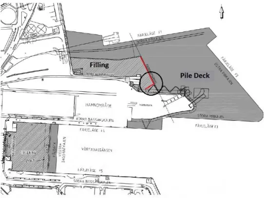
Figure 2.5 - Plan of the Värtahamnen port with location of the corner (Aarsleff 2014)
The corner is constituted by one main wall and a perpendicular smaller wall. The main wall develops parallel to the adjacent pile deck and is supported by two levels of anchors. On the other hand, the smaller wall is connected with tie rods to the main wall, supported in the top corner by an anchor and laterally prevented by neighbouring gravity L wall. Figure 2.6 shows a three dimensional model of the structure for better understanding the previous description. It is clear where the filling material (light blue) is deployed, the location of anchors, the layout of sheet pile wall (dark blue) and the gravity wall (grey).
Figure 2.6 - 3D representation of the sheet pile corner: anchors, sheet pile wall (dark blue), gravity wall (dark grey), filling material (light blue) and soil reinforcement (grey)
Anchors (lower level hidden by filling) Anchors Soil Reinforcement Backfilling Material Soft Clay Glacial Till
Sheet pile wall
Gravity Wall
Corner Ties (lower
level hidden by soil reinforcement)
The description of the entire system and adopted structural model are explained in detail in the following chapters, depending on the type of analysis (analytical or numerical).
Following, is presented a description of the particular aspects that make this special case an important subject of study, as well as some considerations that should be necessary to take into account when analysing and studying the present situation.
2.1.3.1. Corner Effects
In excavations where corners exist it has been verified the occurrence of a phenomenon characterized by the restriction of wall deflection, which is here named as corner stiffening effect. In some situations, this corner effect has such influence on the behaviour of the retaining wall that can be taken into account to, for example, reduce costs in ground improvement (Ou et al. 2008).
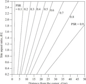
The corner stiffening effect is normally observed in the displacement at the centre of retaining walls far from the corners, where the movement is generally higher than the values observed in areas near the corner. Furthermore, calculated values using plane strain analysis result in much higher deformations than the observed in construction sites at the central section of the retaining wall (Lee et al. 1998). This fact, among others, lead to increasing research by many authors in order to obtain a relationship between the wall displacement and the plain strain analysis calculated displacement. One of the parameters used to develop such studies is the plain strain ratio (PSR), which relates the maximum displacement of a wall in a certain section with the maximum displacement of the same cross section calculated using plain strain analysis. The PSR varies between zero and the unity, when the section in study is in a plain strain condition. Ou et al. (1996) developed a relationship between the PSR and the shape of excavation area, as well as with distance to corners for specific cases, described in Figure 2.7.
Figure 2.7 - Variation of PSR with distance from the corner and aspect of the site (Ou et al. 1996)
excavation, it is not clearly evaluated using only two dimensional plain strain analysis. In fact, it has been verified by many authors that in excavation pits with corners the displacements in centre of excavation walls have higher values when calculated by plane strain finite element analysis than in three dimensional finite element analysis (Ou et al. 2008), (Finno et al. 2007).
The case study in the present thesis, a sheet pile corner under backfilling conditions, is a typical situation that had not been thoroughly studied before and a small amount of information is available on the literature. Therefore, the previously described corner effect might not be the same for excavation and backfill type of loadings on retaining walls, which adds up to the difficulties in predicting the behaviour of the structure.
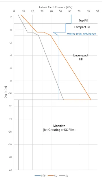
Another possible consequence due to the existence of corners in the sheet pile system may be a similar effect to the known silo effect. This effect was described by Janssen in 1895 as a reduction of the earth pressure in the bottom of silos. Basically, in the top of the silos the vertical earth pressure develops similarly to the typical triangular distribution from Rankine's formulation, but tends to an asymptotic limit as it becomes deeper. Using the shear plane method, it is possible to analytically verify this fact, by simply calculating the static equilibrium of an infinitesimal horizontal layer, taking into account the weight of the soil mass and upwards friction from walls surface resultant of horizontal earth pressure (Widisinghe & Sivakugan 2012). According to the later confirmed Jáky's assumption (Pipatpongsa & Heng 2010), it is plausible to admit at rest pressure conditions and, therefore, K0 as the coefficient of
earth pressure at rest using the horizontal and vertical stresses at centre of the section. By solving the static equilibrium, one obtains a function of vertical stress with the depth in equation (2.1), where D is the silo diameter, K the coefficient of earth pressure at rest,
the soil weight and
the surface roughness. D z K exp K D z 1 4 .tan . tan . 4
( 2.1 )Plotting the equation (2.1) with the depth z, obtains the diagram in Figure 2.8. The parameters used were 2 m as the diameter D, unit weight γ of 21 kN/m3. The surface roughness angle δ corresponds to 2/3 of the friction angle, which was 40º. Earth pressure coefficient K was calculated using Jáky's formula and is dependent on the friction angle. The resultant graph clearly shows the asymptotic tendency of vertical stress as the depth increases. It is interesting to also note that the initial inclination is close to the unit weight of the soil, which indicates that close to the surface the arching effect and consequent silo effect is practically none.
The similarity of the silo shape to the corner shape makes it possible to assume that an analogous effect may occur.
Taking this fact into account, it is possible to expect some influence of the corner in the behaviour of the fill material, resulting in possible reduced earth pressures and increased vertical stresses in the sheet pile wall, among other consequences of this effect.
Figure 2.8 - Relation of vertical earth pressure with depth, revealing silo effect
2.1.3.2. Corner Tie Rods
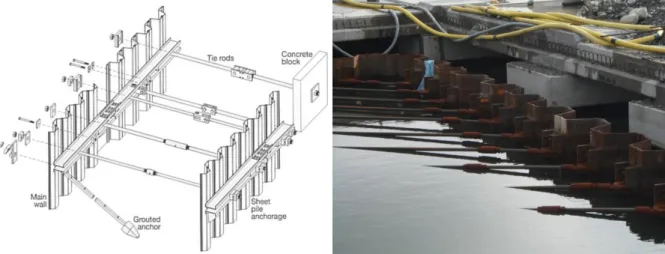
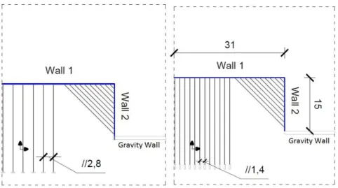
Figure 2.9 shows a plan of the sheet pile wall and placement of anchors rods. On the right side, close to the corner, the walls are mutually supported by a group of 10 tie rods. These structural elements were used instead of anchors due to the difficulties that would be found in placing the anchor blocks of the smaller wall.
Corner Tie Rods Anchors Anchored Wall Mutually supported corner σz ≈ γ*z
In the back side of the wall, where the anchor blocks are located, the fill material will be placed. When the backfill material pushes the wall system outwards it is expected that in the mutually supported corner the group of tie rods work in tension as a response to the tendency of corner opening, resultant from the pushing of both walls. It is an intuitive prediction, but sill the behaviour and distribution of stresses in these structures under such conditions is not totally known and predictable.
In fact, this situation has some similarities with double wall tied cofferdams, which are commonly used for waterfront structures and excavation enclosures (Figure 2.10). These structures consist in two parallel steel sheet pile walls connected by ties, creating a space in between that is filled with granular material, such as sand, gravel or even rock (Gui & Han 2009). Therefore, it is possible to admit that in both cases the wall, and consequently the tie rods are under the same backfill kind of loading.
Figure 2.10 - Example of double wall tie cofferdam (left) and cellular cofferdams (right) (C.J. Mahan)
However, in cofferdams the design is simply done by admitting a plane strain deformation analysis and calculation. In the assumed case of study this may not be correct and possibly is too conservative. Actually, the tie rods stiffness varies along the wall, due to different lengths, as represented in Figure 2.11. As the ties are connected to both walls, it appears to be difficult to calculate the correct stiffness to use in plane strain calculations.
In reality, the most common situation where a similar corner tie rod disposition is used is on cellular cofferdams, normally utilized to retain water and soil out of the excavation pit. Though, these are subjected to external earth pressure, and not to internal backfill pressure.
2.1.3.3. Failure Mechanisms
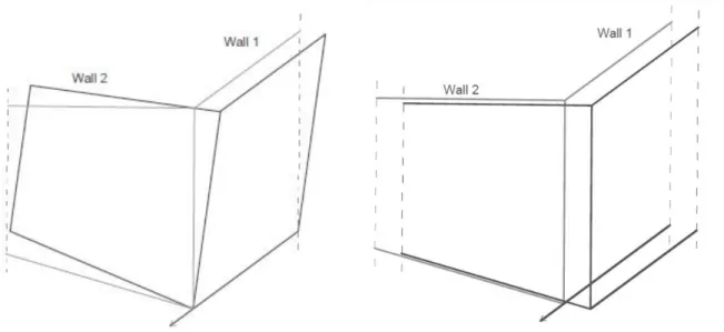
As there is not enough knowledge on the behaviour of this specific structure, two main failure mechanisms were thought a priori when approaching any design of this detail. Translation of wall system and tilt around the longer wall are assumed to occur in the retaining system in the corner, as represented in Figure 2.12, and both are probable to occur simultaneously.
The translation of the corner is expected to occur in the direction perpendicular to the main long wall, named here as wall 1, and may be accompanied by a circular failure of the soil mass in front of the wall. Therefore, the stability is assumed to be assured by the passive resistance of the soil in front of wall 1 and by the anchor system.
The rotation of the structure occurs along the base of wall 1, pushing this wall outwards and the smaller wall, referred as wall 2, upwards. To assure the stability of the corner against rotation, it is thought to make use of the friction with the soil in the back of the wall 2, an anchor in the top of the same wall and passive resistance of soil in front of wall 1,
Figure 2.12 - Expected failure mechanisms in the corner: tilting around tip (left) and translation (right)
2.1.3.4. Soil Reinforcement
The ground in the construction area is mainly composed by a thick layer of soft sediment clay on top of glacial till and bedrock. This is the typical soil profile of the marine soil found in Scandinavia, detailed in Figure 2.13. The layer of till and bedrock prove normally to be competent structures capable of bearing high loads. However, the same cannot be said to the soft marine clay. In fact, the clay material in the region is resultant from the deposition of sediments that have been carried by the network of rivers that shore Stockholm. As the river flow keeps raking the seabed along the time, the clay does not suffer much consolidation. Therefore, it shows low strength parameters that rise up many concerns when building in such conditions.
Figure 2.13 - Typical soil profile from Stockholm coastal area
When such soil conditions are present on site and it is necessary to achieve the required level of strength, techniques of soil reinforcement ought to be used.
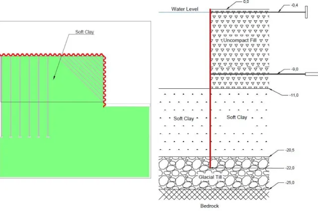
Therefore, lime-cement piles (KC Piles) were applied to the clay seabed using a deep-mixing method all along the back of the sheet pile wall and jet grouting columns done in the critical areas next to the corner, as idealized in Figure 2.14.
It is possible that this improved ground would behave similarly to a monolith, especially in the corner, where a concrete block is likely to be created. This way, the reinforced soil would transmit earth pressures directly to bearing stratum, in this case the glacial till. However, the reduction in earth pressure is not certain, as the behaviour of the KC Piles and jet grouting is not surely known. It should be examined if there is any shear deformation that may induce earth pressures into the sheet pile wall and what is the failure mode of these systems.
2.2.GROUND CONDITIONS
The ground on site assumed in the analysis of the current work is a typical Scandinavian marine soil structure, composed of natural sediments, over a thin layer of natural glacial till, below which lies a very competent bedrock, as outlined in Figure 2.13. At this point, only introductory and geological considerations are done regarding the soil. Though, for each type of analysis in the following chapters the assumed ground profiles and geotechnical properties are provided in detail.
2.2.1.CLAYEY SEABED
The first particular aspect of the ground in situ is the seabed composed by soft clay. As detailed in Figure 2.15, it is a layer of clayey soil varying between 5 and 9 m of thickness, resultant from the deposition of river sediments in the coastal banks. It is a very fine and low permeable material, normally constituted by particles with less than 0.002 mm of diameter and with a plastic behaviour at the appropriate water content. Clay can be classified by the Atterberg limits which relates its behaviour with the water content and also by the plasticity index, liquidity index and activity level. Normally consolidated clay is generally a problematic soil when it comes to design of geotechnical structures. Due to low cohesion, typical undrained behaviour and, in some situations, thixotropy, it is not considerable to completely assure stability of structures such as foundations and sheet pile walls. In the region where the case study is placed, the appearing clay has relatively low values of undrained shear strength, down to 3 kPa.
Figure 2.15 - Soil profile on-site with layers' thickness
2.2.2.GLACIAL TILL
The glacial till is a mix of a wide variety of granular particles, with varying sizes and shapes, from clay to boulders. It was formed by the movements of existing glacial ice in Scandinavia, which transported, eroded and deposited the rock fragments during advance and retreat of the ice mass (Strahler & Strahler 1973).
The granular composition goes from large boulders to fine clay. The smaller elements are formed due to erosion or abrasion between the elements of larger dimension and the bedrock underlying the glacier. Also, as it was deposited due to the melting of ice that contained the debris, it shows little stratification, thus has a less uniform arrangement of particles.
In general, glacial till is a competent and resistant material. In this specific case, the 2 to 5 m layer of till (Figure 2.15) shows a high value of friction angle and therefore has an adequate bearing capacity.
2.3.BACKFILL CONDITIONS
2.3.1.CONSIDERATIONS IN BACKFILLING
One of the peculiar aspects of the situation that is being investigated is the construction method and its design considerations.
As it was stated before, backfilling and excavation are generally two possible construction methods to use with retaining walls. Although in the end of the construction stage the shape is the same, i.e. there is a mass of soil being retained, the loading conditions in the wall and in the soil are different. Therefore, the expected behaviour is dissimilar (Bilgin 2010).
So, in order to calculate the earth pressures for the design of tied sheet pile walls under backfilling conditions some considerations that are taken into account in excavations cannot be assumed. For example, the Terzaghi-Peck diagrams, which are often used to design multi-tied excavations, were developed from results of many observations of excavations in constructions sites.
In reality, some authors that performed the few existing studies regarding backfill conditions concluded that the backfilling method has considerably higher wall deformations compared with excavation. Also, the wall tip deformations are even more affected by the construction method. Moreover, bending moments are significantly higher in backfilling than in excavations (Bilgin 2010). These conclusions lead to uncertainty about the design methods that should be applied to multi-tied sheet pile walls under backfilling conditions.
Regarding the procedures of construction, backfilling is done by layers that in the current situation, as the fill is submerged, will not be well compacted. In marine works, it is normally a dredge that spreads the material in layers. Though, the top layers, which will be used for infrastructure, are normally compacted and its application more controlled.
2.3.2.BACKFILL MATERIAL
The fill material is described as a frictional material, with high values of friction angle. It is composed of gravel and large sharp boulders (see Figure 2.16), retrieved normally from other ground works, resultant from blasting and excavation. The large elements sizes give the soil high levels of permeability, providing it with a drained behaviour.
The main function of the so called Sprängsten (translated to blasted) is to provide the base for the construction of infrastructures necessary for the port. While the lower layers serve solely as capable filling, the top layers will cover the underground service systems of the building, such as the drainage systems (Figure 2.17) and will be the contact layer with the structures above. Therefore, the material applied above water level has to be well compacted and its performance controlled.
Figure 2.16 - Samples of the Sprängsten material used as backfill
The interaction of the backfill material with the sheet pile wall is of main interest when analysing the behaviour of the structure. Actually, such interface characteristic should be studied to understand the effect of interface resistance (surface roughness) in lateral pressures on the wall and any disturbances in corner effects.
Figure 2.17 - Drainage system installed before applying top layer of filling material
2.4.ELEMENTS OF ANCHORED SHEET PILE WALL
2.4.1.SHEET PILE WALL
In order to retain the soil that will become the foundation ground for infrastructures of the port, sheet pile walls were used as the retaining system.
These types of retaining structures, commonly known as LARSSEN sheet piles, are applied in different situations that include excavations, waterfront structures, bridge abutments, cuttings, landfill,
flood protection and other ground enclosures. Therefore, it is a widely utilized system, with many advantages in engineering, such as:
favourable ratio of cross-section to moment of resistance;
suitability for a wide variety of soils;
possibility to use in water conditions;
fast implementation on site;
possibility to reuse;
Low permeability, with watertight interlocks.
In the actual market several types of sheet pilling are available, varying mainly with section shape and material grade. In fact, it has been for many years that sheet piles made of wood were used in old constructions, as well as concrete jetted piles, aluminium and even vinyl (Eskandari & Kalantari 2011). However, steel is the most popular material used due to high strength and easy application. The generally used steel sheet pile sections are the U and Z sections shown in Figure 2.18, although exist also other types such as straight-web sections, normally used in cofferdams.
Figure 2.18 - U (left) and Z (right) steel sheet pile sections and correspondent interlocks
The main difference between these sections is focused on the position of the interlocks. Interlocks are elements responsible for joining together single piles to shape the complete sheet pile wall. They are normally mechanically crimped together to assure a good connection between the piles and, in some situations, welded as well. In U sections, interlocks coincide with the neutral axis, where the maximum shear stresses are located, whereas in Z sections they are located in the area with minimum shear stresses. Therefore, the efficiency of the section and section properties in U profiles is reduced in comparison with the Z profiles. In the present scenario, Z profiles are used with varying lengths depending on the location.
Normally, sheet piles are driven individually in the soil using existent methods that differ on the situation where the sheet pile is applied. Among the mostly used, it is possible to differentiate between threading, pressing, impact-driven and vibrated.
The first technique of driving the piles, threading, consists in simply drilling a hole or a excavating a trench where the sheet piles will be placed. Necessarily, the piles can be afterwards driven to their desired depth.
Pressing is, as threading, a low noise method for driving piles. It is mainly used in areas where low noise and vibration is a requirement, which is the case of constructions in urban residential areas or close to existing buildings, and even on embankments. As schemed in Figure 2.19, the technique
simply consists on a pressing plant which forces down the piles by means of a hydraulic system, using the self-weight of the equipment and the resistance of the already driven sheet piles as reaction force.
Figure 2.19 - Hydraulic system used for pile driving pressing method (ThyssenKrupp 2010)
Other two options of driving piles are the impact and vibratory driving, described in Figure 2.20. The first involves applying the piles into the ground with a series of strikes produced by a weight dropped from a certain height, lifted by hydraulic systems. The blows per minute required depend on the soil and on the type of hammer being used. In case of cohesive soils, low frequency hammering is applied to ensure dissipation of pore water pressure between blows. However, for light driving weight, rapid reaction hammers can be used.
Finally, vibratory driving is based on the harmonic loading of the sheet pile. Consequently, the soil is redistributed and reduction of toe resistance occurs, as well as decrease of friction between soil and sheet pile, associated with a local liquefaction of the soil in this interface. The applied force Fd is
related to the static moment, the product of mass weight
m
u and distance to the point of rotationr
u,and to the frequency of excitation
, as described in equation (2.2). By adjusting the frequency of the harmonic excitation it is possible to adapt the applied force to the soil properties in order to achieve optimal driving evolution. However, when operating these equipment, it is necessary to take into account the passage through low frequencies, which can excite natural frequencies of nearby buildings (1-5 Hz). 2
u u dm
r
F
( 2.2 )Also, when using the impact or vibration method to drive sheet piles it is important to take into account ground vibrations that propagate in the subsoil, that can not only cause damage to close building due to vibration but also cause compaction of soil, and consequently not predicted settlement.
Figure 2.20 - Representations of impact (left) and vibration (right) pile driving methods (ThyssenKrupp 2010)
2.4.2.ANCHOR RODS
The system used to support the sheet pile walls is an anchorage system, as detailed in Figure 2.9. The anchor rods transmit the horizontal earth stresses applied on the sheet pile wall to the anchor plates. Therefore, anchor rods are important and critical elements that will carry high loads and assure the stability of the wall.
For anchorage systems to be effective, one important aspect to keep in mind is that anchorages have to be situated outside the active failure zone that will exist behind the sheet pile wall. This means that anchor rods will most of the times have long lengths. In the assumed situation, as the back of the sheet pile wall will be filled after the installation of the piles, the anchorages need to be placed previously in the existent soil mass, far from the wall. Therefore, the anchor rods will have lengths varying from 25 to 50 m.
In simply tied walls, the calculation of anchor forces is relatively simple and direct, as it is not an indeterminate system. However, in the case of multi-tied walls the system becomes highly indeterminate due to the existence of various anchor levels. Though, in both situations an accurate value of the load in the tie rod can be difficult to determinate due to factors such as the variability of the retained mass and the arch effect in the soil. An approach on the design methods of anchors is presented in the following chapter.
When designing the tie rods, it should be taken into account the possible situation of failure of one rod and consequent redistribution of load from the missing tie to both neighbouring ties. This may require increased resistance of tie rods. Moreover, for permanent anchors, it is necessary to satisfy demands regarding corrosion protection and long term resistance.
Also, it is necessary to check axial deformation of tie rods under service load, to assure the wall deformations are below the adopted limit. However, such movements can be reduced in many cases by pre-loading the tie rods while being installed. Furthermore, bending and shear stresses caused by settlement of the fill should be considered when designing the rods, though this can be overcome by introduction of articulated joints.
The general technique used to connect the tie rods is by bolting in the opposite side of the wall, with a plate in between to avoid punching (Figure 2.21). However, in some situations where it is not so easy to do this way, such as a corner situation, it is possible to use, for example, the MACALLOY type rods. These are connected to a part called "eye piece" bolted to the wall, allowing an oblique connection and lateral movement.
Figure 2.21 - Example of connections of the tie rods to the sheet pile wall: normal bolting with plate (left) and MACALLOY type rods (right)
2.4.3."DEADMAN"ANCHOR
The most important element of the anchorage system is the anchor itself. This component is responsible for transmitting the earth loads imposed on the sheet pile wall to the resistant soil behind the wall. As they are dependent on the soil resistant properties, anchors are critical parts of the anchorage system.
The ground anchor types differ mainly on the form of construction. It is possible to admit the following types, also shown in Figure 2.22:
Anchor wall/plate;
Grouted Anchors;
Driven Anchor Piles;
Driven grouted Pile;
Raking Piles.
For cases where the sheet pile wall is backfilled, such as in quay walls, mainly anchor plates or deadman anchors can be used (Figure 2.23). The resistance of these constructions is activated upon backfilling the wall and is composed of the horizontal passive earth pressure plus the vertical weight acting on the anchor, which can actually be made of another sheet pile wall that reacts when the rod is tensioned. In such situation, the design might be similar to the design approach used in cofferdams.
Figure 2.22 - Example of different anchoring techniques (ThyssenKrupp 2010)
In the exposed situation, deadman anchors were applied. The main characteristic of these is that they are generally a large block of concrete that is simply laid on the fill. Also, its weight has a greater consideration in the stability of the anchorage system. The shape of these anchors can vary, from the classical thin plate shape, to the longer pile shape. This last also has an important resistant component associated with skin friction between the anchor and the soil.
Figure 2.23 - Representation of a deadman anchor (side cut)
When designing the anchors, it is necessary to take into account the following aspects regarding the location of the blocks:
Assure that in the location chosen the passive failure wedge from the toe of the anchor does not coincide with active failure zone (Figure 2.24);
In the case of cohesive soils, it should be located outside the slip circle. Also, it must be in such a distance so that it has enough shear resistance from the soil wedge in front of the anchorage (Figure 2.25).
To design the size and shape of the blocks, related to the resistance of the anchors, the following should be kept in mind:
Limit deformations of wall under serviceability limit state conditions;
Prevent the movement between the block and surrounding soil.
Internal stability of the block, due to punching.
Figure 2.24 - Admissible location of anchor blocks (ThyssenKrupp 2010)
2.4.4.WALING AND CAPPING BEAM
The waling and capping beam are two elements of the sheet pile wall responsible for redistributing the reaction forces between the sheet pile wall and the anchors. Also, both provide higher stiffness to the wall, as well as connection between piles to prevent vertical shear and consequent relative vertical movement. However, typically the waling beam is made of steel and located in intermediate heights of the sheet pile wall, whereas the capping beam is built on top of the wall, working as a cap (Chu 2010).
Figure 2.26 - Representation of waling beam (left) and concrete capping beam (right)
When designing these structures, the structural model of the beams should be considered simple supported with point loads applied by the anchor loads. Still, beams can alternatively be considered continuous and thus with fixed supports. Yet, this procedure is less conservative than the first option. Also, during the design, the possible loss of a tie rod has to be checked and a waling length of two times the single length should be considered.
The capping beam should in addition be designed to resist shear stresses due to relative vertical wall movement resultant of differential settlements or lateral bending. Besides, in the case of quays where the capping beam is the mooring zone, the stresses caused by the contact with mooring ships should be taken into account and additional safety measures should be considered.
2.5.SOIL IMPROVEMENT
2.5.1.KCPILES
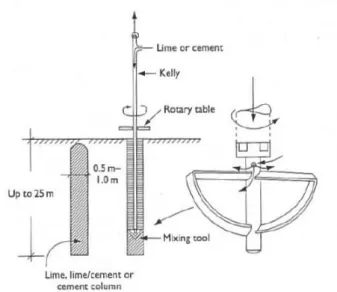
Lime-cement piles, or in Swedish, Kalkcementpelare (KC Piles), are result of a soil stabilization technique where quicklime or cement are mixed in situ with soft soil, which can be constituted by soft clay or silt as well as organic soils. In the application of this method, a mixing tool ("egg beater") rotates as it goes deeper in the ground, remoulding the soil. When the required depth is reached, the required mix of lime, lime-cement or cement is supplied and mixed with the stabilizing soil, as the mixing tool rotates and returns to the surface (see Figure 2.27).
The use of lime-cement columns has been increasing since their development in the 1970's (Broms & Boman 1975). The method has been used in situations where soft marine deposits are existent, such as in ports and harbour areas, with the main purposes of increasing load bearing and reducing ground settlements. Application of such techniques has also extended to embankments, roadways and foundations in soft ground.
Figure 2.27 - Execution of dry mixing lime, lime-cement or cement pile (Moseley & Kirsch 2004)
Most commonly used at the present time in Japan and in Scandinavian countries, such as Sweden and Finland, KC Piles have turned out to be a competitive solution for soil improvement and stabilization. It actually became an alternative for ground improvement that, although may appear more costly due to use of finely ground quicklime, has a lower total cost as less lime than cement is required (Moseley & Kirsch 2004).
The main idea of soil improvement when using blocks of KC Piles is increasing bearing resistance and shear strength. This is mainly achieved by the chemical reactions between lime, cement and soil particles. What can be observed is that the quicklime reacts with fine particles of clay, occurring flocculation, whereas the cement reacts and agglomerates granular particles. So, lime-cement mixes are recommended to use in organic soils when the desired shear strength cannot be obtained with other mixes.