Repositório ISCTE-IUL
Deposited in Repositório ISCTE-IUL:
2018-12-10Deposited version:
Post-printPeer-review status of attached file:
Peer-reviewedCitation for published item:
Sequeira, D. G., Cancela, L. G. & Rebola, J. L. (2018). Impact of physical layer impairments on multi-degree CDC ROADM-based optical networks. In 22nd Conference on Optical Network Design and Modelling, ONDM 2018. (pp. 94-99). Dublin: IEEE.
Further information on publisher's website:
10.23919/ONDM.2018.8396113Publisher's copyright statement:
This is the peer reviewed version of the following article: Sequeira, D. G., Cancela, L. G. & Rebola, J. L. (2018). Impact of physical layer impairments on multi-degree CDC ROADM-based optical
networks. In 22nd Conference on Optical Network Design and Modelling, ONDM 2018. (pp. 94-99). Dublin: IEEE., which has been published in final form at
https://dx.doi.org/10.23919/ONDM.2018.8396113. This article may be used for non-commercial purposes in accordance with the Publisher's Terms and Conditions for self-archiving.
Use policy
Creative Commons CC BY 4.0
The full-text may be used and/or reproduced, and given to third parties in any format or medium, without prior permission or charge, for personal research or study, educational, or not-for-profit purposes provided that:
• a full bibliographic reference is made to the original source • a link is made to the metadata record in the Repository • the full-text is not changed in any way
The full-text must not be sold in any format or medium without the formal permission of the copyright holders.
Serviços de Informação e Documentação, Instituto Universitário de Lisboa (ISCTE-IUL) Av. das Forças Armadas, Edifício II, 1649-026 Lisboa Portugal
Phone: +(351) 217 903 024 | e-mail: [email protected] https://repositorio.iscte-iul.pt
Impact of Physical Layer Impairments on
Multi-Degree CDC ROADM-based Optical Networks
Diogo G. Sequeira
1, Luís G. Cancela
1,2, and João L. Rebola
1,21 Optical Communications and Photonics Group, Instituto de Telecomunicações, Lisbon, Portugal 2 Department of Information Science and Technology, Instituto Universitário de Lisboa (ISCTE-IUL), Portugal
Emails: [email protected]; [email protected]; [email protected]
Abstract—Nowadays, optical network nodes are usually based
on reconfigurable optical add/drop multiplexers (ROADMs). Due to exponential growth of internet data traffic, ROADMs have evolved to become more flexible, with multi-degree and their add/drop structures are now more complex with enhanced features, such as colorless, directionless and contentionless (CDC). In this work, the impact of in-band crosstalk, optical filtering and amplified spontaneous emission noise on the performance of an optical network based on multi-degree CDC ROADMs is studied considering 100-Gb/s polarisation division multiplexing quadrature phase-shift keying signals for the fixed grid. We show that, an optical signal can pass through a cascade of 19 CDC ROADMs, based on a route and select architecture with 16-degree, until an optical signal-to-noise ratio (OSNR) penalty of 1 dB due to in-band crosstalk is reached. We also show that the ASE noise addition, due to the increase of the number of CDC ROADMs, is more harmful in terms of OSNR penalty than in-band crosstalk.
Keywords: ASE noise, CDC ROADMs, coherent detection, in-band crosstalk, optical filtering, PDM-QPSK.
I. INTRODUCTION
The exponential growth of internet data traffic due to the increase of the number of devices, cloud and video-on-demand services, has been putting fibre optic network technologies in a continuous development to support all the data generated. Technologies, such as dense wavelength-division multiplexing, optical coherent detection, polarisation division multiplexing (PDM) and advanced digital signal processing (DSP) are now fundamental to achieve the huge transport capacities required by the overall telecommunications infrastructure [1].
In addition to these technologies, the reconfigurable optical add/drop multiplexers (ROADMs) nodes evolution is also very important to support this exponential growth. In the past, the network nodes were static and their configuration was manual. Nowadays, these nodes became more reconfigurable with colorless, directionless and contentionless (CDC) features [2], that improves the routing and switching functionalities in the optical nodes, making them more dynamic and reliable.
On the other hand, the optical network physical layer impairments (PLIs) require a comprehensive study since the optical signal along its path, passes through optical fibre links as well as optical components inside the ROADMs, such as optical switches, (de)multiplexers and splitters/couplers. The losses, noises and interferences generated in these links accumulate along the light-path degrading the optical signal transmission. In particular, the imperfect isolation of switches
and filters inside the ROADMs leads to signal leakages that originate interfering signals known as crosstalk signals. One of the crosstalk types that becomes enhanced in an optical network and degrades the optical network performance is the in-band crosstalk [3]. This type of crosstalk occurs when the interfering signals have the same nominal wavelength as the primary signal but are originated from different sources, so that this impairment cannot be removed by filtering. In an optical network based on ROADMs, the in-band crosstalk will accumulate over the ROADM cascade and can limit the number of nodes that the signal passes in the network [4]. In the literature, some studies were performed to address the impact of the in-band crosstalk on the optical network performance, however with a simple ROADM model, i.e., considering only a WSS cascade [5] or not considering the ROADM add/drop structures with the CDC features [6].
In this work, the impact of in-band crosstalk generated inside multi-degree CDC ROADMs on the network performance is studied through Monte-Carlo simulation. Polarization division multiplexing quadrature phase-shift keying (PDM-QPSK) signals at 100-Gb/s for the fixed grid are considered. This study is performed by properly modelling the in-band crosstalk generation inside the ROADMs. Different ROADM architectures, namely broadcast and select (B&S) and route and select (R&S) architectures [6], as well as, different add/drop structures, based on multicast switches (MCSs) and wavelength selective switches (WSSs) [7], are considered.
This paper is organized as follows. Section II describes the model for studying the in-band crosstalk inside a ROADM node, and the number of in-band crosstalk terms generated inside a ROADM is quantified, for both B&S and R&S architectures. Details on the ROADM transponder, as well as, on the ROADM add/drop structures are also provided in this section. In section III, the PLIs such as the optical filtering, amplified spontaneous emission (ASE) noise and in-band crosstalk in an optical network based on multi-degree CDC ROADMs are studied and their impact on the network performance is assessed. Finally, in section IV, the conclusions of this work are presented.
II. MODELLING THE IN-BAND CROSSTALK INSIDE A ROADM The main focus of this section is on the in-band crosstalk generation inside a ROADM node. In subsections II.A and II.B, we will describe, respectively, the ROADM transponder features and the ROADM add/drop structures. Subsection II.C deals with the in-band crosstalk generation.
A. ROADM Transponder
We present in this sub-section the main blocks of the coherent receiver of a ROADM transponder, used for detecting the optical signal that is dropped in a ROADM. Fig. 1 depicts the block diagram of the coherent receiver for a single polarisation of the signal. The coherent receiver with dual polarisation consists of two polarisation beam splitters connected with two structures identical to the one depicted in Fig. 1. In this work, we assume that the optical receiver is ideal, so the receiver performance can be assessed considering only the structure of Fig. 1 for a single polarisation of the signal [8]. The structure of the optical coherent receiver is formed by a 2×4 90º hybrid, which has 𝐸𝑟(𝑡) and 𝐸𝐿𝑂(𝑡), respectively, the complex envelope of received signal and local oscillator (LO) electrical fields as inputs. The received electrical signal corresponds to the signal under test, the primary signal, dropped by a ROADM. The 2×4 90º hybrid is followed by two balanced photodetectors. The hybrid, which is modelled as in [8], is composed by four 3 dB couplers and a 90º phase shift in the lower branch, which allows the receiver to decode the in-phase and quadrature signal components of the received currents, respectively, 𝐼𝑖(𝑡) and 𝐼𝑞(𝑡) in Fig. 1. An electrical filter is placed after the balanced photodetector, to reduce the inter- -symbolic interference and the noise power, consequently, improving the signal-to-noise ratio [9]. In this work, we use a 5th order Bessel filter as the receiver electrical filter, which is a typical filter used in several studies [10]. The 3 dB bandwidth of this filter is set equal to the symbol rate. After electrical filtering, the signal is sampled by an analog-to-digital converter before going to a DSP (not shown in Fig. 1). Finally, a decision on the transmitted symbol is taken at the decision circuit.
3 dB Er (t) 3 dB 3 dB 3 dB ELO (t) 2 × 4 90º hybrid Balanced photodetector Balanced photodetector Iq (t) Ii (t) 90º Electrical Filter Electrical Filter Decision Circuit Decision Circuit
Fig. 1. Coherent receiver block diagram for a single polarisation QPSK signal. B. ROADM Add/Drop Structures
In this subsection, we present the internal structure of a ROADM add/drop structure based on both MCSs and WSSs. Fig. 2 shows a generic internal structure of (a) MCSs and (b) WSSs that can be used in the drop section of a CDC ROADM [7]. As we can observe from this figure, the MCSs are based on 1×M splitters and N×1 optical switches. As such, they are not wavelength selective as the WSS structures. On the other hand, the WSS structures have higher costs. However, in terms of in-band crosstalk generation, since inside a N×M WSS, the interfering signals pass through the isolation of two WSSs, the interferers are second order interferers, instead of the first order interferers that appear on the N×M MCSs outputs.
N×1 Optical Switches N×M MCS Splitter 1×M Splitter 1×M ... ... ... ... N×M WSS WSS 1×M ... WSS 1×M WSS N×1 WSS N×1 ... ... ... ... ... (a) (b) ... ... 1 M 1 N N 1 M 1 ... ...
Fig. 2. ROADM drop section structure based on (a) MCS and (b) WSS. C. In-Band Crosstalk Generation inside a ROADM
For studying the number of crosstalk terms generated inside a ROADM with degree R, we consider, a four-node star network with a full-mesh logical topology as depicted in Fig. 3. As a worst-case scenario, we assume that the central ROADM, node 2, communicates with other nodes using the same wavelength, λ1. This means that, the wavelength λ1 reaching node 2, is dropped and new optical signals with the same wavelength λ1 are added and directed to the ROADM outputs.
1 2 4 3 l1 l1 l4 l1 l3 l2 North East South
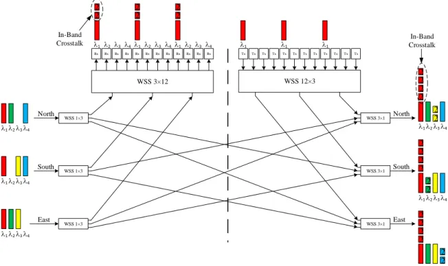
Fig. 3. Four-node star network with a full-mesh logical topology. Fig. 4 represents the structure of the ROADM designated by node 2 in Fig. 3, a 3-degree CDC ROADM based on a R&S architecture, i.e., with WSSs both at its inputs and outputs, and with WSSs-based add/drop structures. The crosstalk generation inside the ROADM is also represented. From this figure, we can observe that all in-band crosstalk terms originated with wavelength λ1 are second order terms (identified with number 2). In this case, in each drop port, where wavelength λ1 is dropped, we find two in-band crosstalk terms, coming from the other two ROADM inputs. At the ROADM outputs, the output wavelength λ1 in each direction is impaired by four in-band crosstalk terms, two of them arising from the ROADM inputs and the other two are generated from the presence of wavelengths λ1 at the add section.
l1 l2 l3 l4 l1 l2 l3 l4 l1 l2 l3 l4 l1 l1 l1 Tx Tx Tx Tx Tx Tx Tx Tx Tx Tx Tx Tx Rx Rx Rx Rx Rx Rx Rx Rx Rx Rx Rx Rx l1 l2 l3 l4 l1 l2 l3 l4 l1 l2 l3 l4 WSS 3×12 WSS 12×3 WSS 1×3 WSS 1×3 WSS 1×3 WSS 3×1 WSS 3×1 WSS 3×1 l1 l2 l3 l4 l1 l2 l3 l4 l1 l2 l3 l4 North East South North East South 2 2 2 2 2 2 2 2 2 2 2 2 2 2 2 2 2 2 2 2 2 2 2 2 In-Band Crosstalk In-Band Crosstalk
Fig. 4. Node 2 structure – a 3-degree CDC ROADM based on a R&S architecture with WSSs-based add/drop structures. The conclusions taken from Fig. 4, for a 3-degree CDC
ROADM, can be generalized for a R-degree ROADM. In Tables 1 and 2, the number of in-band crosstalk terms generated inside a R-degree C, CD and CDC ROADM with MCSs and WSSs-based add/drop structures, for both B&S (Table 1) and R&S (Table 2) architectures is presented. From Tables 1 and 2, we can conclude that, for a CDC ROADM, the WSS-based add/drop structures are the best choice in terms of minimizing the in-band crosstalk generation. For both studied architectures, the interfering signals generated with these add/drop structures are mainly of second order. In summary, to minimises the crosstalk generation inside multi-degree CDC ROADMs, the R&S architecture with WSSs-based add/drop structures seems to provide the best solution.
Table 1. Number of in-band crosstalk terms generated inside a
R-degree ROADM based on the B&S architecture.
Drop ports Outputs
1st order 2nd order 1st order 2nd order
C - - 𝑅 − 1 -
CD 𝑅 − 1 - 2(𝑅 − 1) -
CDC (MCSs) 𝑅 − 1 - 2(𝑅 − 1) -
CDC (WSSs) - 𝑅 − 1 𝑅 − 1 𝑅 − 1
Table 2. Number of in-band crosstalk terms generated inside a
R-degree ROADM based on the R&S architecture.
Drop ports Outputs
1st order 2nd order 1st order 2nd order
C - - - 𝑅 − 1
CD 𝑅 − 1 - 𝑅 − 1 𝑅 − 1
CDC (MCSs) 𝑅 − 1 - 𝑅 − 1 𝑅 − 1
CDC (WSSs) - 𝑅 − 1 - 2(𝑅 − 1)
III. PHYSICAL LAYER IMPAIRMENTS IMPACT
In this section, the impact of in-band crosstalk, optical filtering and ASE noise in a cascade of multi-degree CDC ROADMs based on the R&S architecture, the architecture that minimises the generation of in-band crosstalk, with MCSs and WSSs-based add/drop structures is studied. The main goal of this study is to investigate the maximum number of ROADMs that an optical signal can pass until the degradation of these PLIs causes an optical signal-to-noise ratio (OSNR) penalty higher than 1 dB. The signal referred in this work as the primary signal corresponds to the signal that is taken as a reference to study the PLIs. We consider a non-return-to-zero (NRZ) QPSK signal with 50-Gb/s in a single polarisation (which corresponds to 100-Gb/s in dual polarisation) as the primary signal.
We start, in subsection III.A, by characterising the optical filters used to model the ROADM components. This will permit to obtain the crosstalk level at the end of an optical network. In subsection III.B, the optical filtering impact on a cascade of CDC ROADMs considering only one amplification stage is studied. In subsection III.C, the impact of ASE noise is studied with optical amplifiers at every ROADM inputs and outputs. A. Optical Filters used to Model the ROADM Components
We consider two types of optical filters to model the ROADM components, the passband 𝐻𝑝(𝑓) and the stopband 𝐻𝑏(𝑓) filters. The signals that pass through the ROADM components (e.g. WSSs) are filtered by the passband filter, while the signals that the ROADM component blocks are filtered by the stopband filter. The optical passband filter is modelled by a 4th order Super-Gaussian optical filter [11] with 3 dB bandwidth (B0) equal to 41 GHz, usually used for the 50 GHz channel spacing [5]. The optical stopband filter is
modelled by the inversion of the optical passband filter and by setting the blocking amplitude, in dB, with B0 equal to approximately 48 GHz. Fig. 5 shows the transfer functions of these filters, Fig. 5 (a) for the passband filter and Fig. 5 (b) for
the stopband filter with different blocking amplitudes (i) 20 dB, (ii) 30 dB, (iii) 40 dB and (iv) 50 dB.
(a) (b)
Fig. 5.Transfer function of the (a) optical Super-Gaussian 4th order passband filter 𝐻𝑝(𝑓) and (b) optical stopband filters 𝐻𝑏(𝑓) with different blocking
amplitudes (i) 20 dB (ii) 30 dB (iii) 40 dB and (iv) 50 dB. With these passband and stopband filters, we can model the effect of the ROADM node on both the express and add/drop signals and also on the crosstalk signals. For the add/drop signals, considering the MCS structure, the signals pass through one passband filter, while with the WSS structure, the signals pass through two passband filters. The express signals are filtered by two passband filters, at the ROADM input and output WSSs. Regarding the crosstalk signals, second order terms pass through two stopband filters inside the ROADM, while first order terms pass only through one stopband filter.
Now, we can evaluate the crosstalk level at the end of an optical network composed by 32 cascaded CDC ROADMs with MCSs and WSSs-based add/drop structures, for several ROADM degrees and for the blocking amplitude of 20 dB, as shown in Table 3. Studies with lower blocking amplitudes (50, 40 and 30 dB) exhibit crosstalk levels at the end of a cascade of 32 CDC ROADMs, that will lead to a negligible performance degradation. For a blocking amplitude of 20 dB, the total crosstalk level, as defined in [3], at the end of a network with 32 16-degree CDC ROADMs is 5.2 dB and 13.3 dB, respectively, with MCSs and WSSs add/drop structures. Table 3. Total crosstalk level at the end of an optical network composed by 32
cascaded CDC ROADMs for a blocking amplitude of 20 dB.
Total crosstalk level [dB]
ROADM degree (R) MCSs WSSs
2-degree 18.7 35.4
4-degree 13.3 21.6
8-degree 9.4 16.3
16-degree 5.2 13.3
B. Impact of Optical Filtering and In-Band Crosstalk on a ROADM Cascade with Only One Amplification Stage In this subsection, we study the impact of optical filtering and in-band crosstalk on a ROADM cascade with only one amplification stage at the end of the optical network, as shown in Fig. 6. The optical (de)multiplexers represented in Fig. 6 are for 50 GHz channel spacing and are modelled by the optical passband filter 𝐻𝑝(𝑓) represented in Fig. 5 (a).
2nd ROADM 1st ROADM Mth ROADM Sin So,1 So,M-1 So,M ... So,2 HMux HDemux Coherent Receiver Sin,f ASE noise X1,add X2,add
X1,in X2,in XM,in
+
Fig. 6. Schematic model of an optical network composed by M ROADMs with only one amplification stage.
The signals represented by 𝑋𝑀,𝑖𝑛 and 𝑋𝑀,𝑎𝑑𝑑 are, respectively, the in-band crosstalk signals from the ROADM inputs and add section. The signal 𝑆𝑖𝑛,𝑓 is the primary signal after passing through the optical multiplexer. The primary signal that appears at Mth ROADM output is called 𝑆
𝑜,𝑀, and the ASE noise is added to this signal. In this work, the ASE noise is considered to be an additive white Gaussian noise.
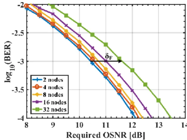
We start by studying the impact of the optical filtering due to the amplitude distortion introduced by the optical passband filters cascade. Fig. 7 depicts the bit error rate (BER) as a function of the required OSNR for a 50-Gb/s NRZ QPSK signal that passes through 2, 4, 8, 16 and 32 ROADM nodes without the in-band crosstalk impairment. The OSNR difference between the case where the primary signal passes 2 nodes, our reference case, and the other cases, represents the OSNR penalty due to the optical filtering, which is estimated for a BER of 103. This penalty is represented in Fig. 7 by δF for the case of 32 ROADM nodes (green curve) and is approximately 1.2 dB.
δF
Fig. 7. BER as a function of the required OSNR for a 50-Gb/s NRZ QPSK signal that passes through a cascade of ROADM nodes.
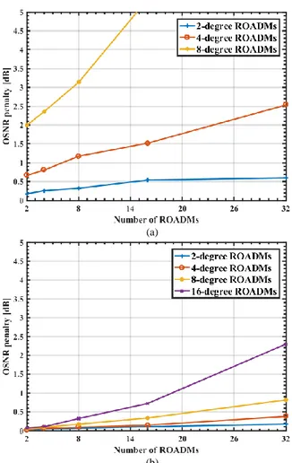
After having evaluated the optical filtering penalty without the in-band crosstalk, we add the in-band crosstalk signals to our simulation model to estimate the OSNR penalty due to in- -band crosstalk [12], considering a ROADM-based network. Fig. 8 depicts the OSNR penalty as a function of the number of ROADM nodes, with the ROADM degree as a parameter, considering a blocking amplitude of 20 dB and (a) MCSs and (b) WSSs-based add/drop structures. For 16-degree ROADMs and MCSs-based add/drop structures, the OSNR penalty is higher than 5 dB at the end of 2 cascaded ROADMs, and it is not represented in Fig. 8 (a). Note that, for a 4-degree ROADM with MCSs-based add/drop structures, the OSNR penalty due
to in-band crosstalk after 2 nodes is about 1.3 dB. This OSNR penalty is higher than at the end of 32 ROADMs with 2, 4 and 8-degree with add/drop structures based on WSSs. When we have WSSs-based add/drop structures, the number of ROADMs associated with a 1 dB OSNR penalty is 15 for 16-degree ROADMs and 28 for 8-degree ROADMs. The 2 and 4-degree ROADMs provide penalties below 0.5 dB at the end of 32 nodes. For case with 4-degree (red curve in Fig. 8 (b)), the OSNR penalty is only 0.4 dB. On the other hand, in the same case but with add/drop structures based on MCSs, the OSNR penalty due to the in-band crosstalk is 3 dB.
(a)
(b)
Fig. 8. OSNR penalty as a function of the number of ROADMs nodes, with the ROADM degree as a parameter, for a blocking amplitude of 20 dB and
with the add/drop structures based on (a) MCSs and (b) WSSs.
C. Impact of ASE Noise and In-Band Crosstalk on a ROADM Cascade with Amplification Stages at every ROADMs Inputs and Outputs
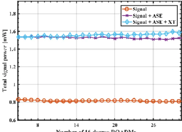
In this subsection, we analyse the impact of the ASE noise and in-band crosstalk on a network composed by a cascade of CDC ROADMs in a more realistic scenario. In this scenario, there are optical amplification stages at the inputs of all the ROADMs to compensate the path losses, and at the ROADMs outputs to compensate the losses inside the nodes [13], as depicted Fig. 9. In Fig. 9, the path of the primary signal, since it is added until it is dropped, is represented by the red line. Notice that, in the network represented in Fig. 9, an increase on the number of ROADMs, besides leading to a higher number of interferers, also leads to a substantial increase of the ASE noise power. To study this effect, we plot in Fig. 10 the total signal power evolution as a function of the number of 16-degree CDC ROADM nodes that the signal passes for three cases: 1) considering only the signal power evolution, 2) considering the signal power plus the ASE noise power and 3) considering the signal power plus ASE noise and in-band crosstalk powers. These results are plotted considering WSSs-based add/drop structures and a blocking amplitude of 20 dB. This figure shows that, the ASE noise power is by far superior to the in-band crosstalk power, as we can check by comparing the curves with crosses and diamonds.
Fig. 10. Total signal power as a function of the number of 16-degree CDC ROADMs with WSSs-based add/drop structures.
. . .
... Sin,fX1,add2 X1,add N
So,1
...
So,2
1st R-degree ROADM 2nd R-degree ROADM Mth R-degree ROADM
X1,in1 X1,in2 X1,inR + + + ASE noise Add Structure N× 1 W S S ASE noise . . . ... X2,add2 X2,add N X2,in2 X2,inR + + + ASE noise Add Structure N× 1 W S S ASE noise . . . XM,inR So,M-1 XM,in2 + ASE noise + ASE noise So,M . . . + + + ASE noise Drop Structure ASE noise . . . Add signal Express signal 1×N WSS 1×N WSS 1×N WSS . . . 1×N WSS 1×N WSS 1×N WSS . . . . . . 1×N WSS 1×N WSS 1×N WSS ... ... Drop signal ... ...
Fig. 11 depicts the OSNR penalty as a function of the number of ROADMs nodes for stopband filters with blocking amplitude of 20 dB and add/drop structures based on (a) MCSs and (b) WSSs in a network depicted in Fig. 9. By comparing the results depicted in Figs. 8 and 11, we can observe that the OSNR penalty due to the in-band crosstalk obtained in Fig.11 is lower than the penalty obtained in Fig. 8. For example, in subsection III.B, the number of CDC ROADMs with WSSs-based add/drop structures, that can be reached associated with a 1 dB OSNR penalty is 15, for 16-degree ROADMs, and 28, for 8-degree ROADMs. In this subsection, Fig. 11 (b) shows that, for 16-degree ROADMs, the maximum number of nodes reached is 19 nodes. For 8-degree ROADMs, a 1 dB OSNR penalty is not reached at the end of 32 nodes.
(a)
(b)
Fig. 11. OSNR penalty as a function of the number of ROADMs for a blocking amplitude of 20 dB and add/drop structures based on (a) MCSs and
(b) WSSs with amplification at every ROADMs inputs and outputs. IV. CONCLUSIONS
In this work, the performance of an optical network based on multi-degree CDC ROADMs impaired by in-band crosstalk, ASE noise and optical filtering has been investigated considering a 100-Gb/s QPSK signal for the fixed grid. The ROADM model considers different architectures and add/drop structures.
It is shown that the R&S architecture is the most robust architecture in terms of the in-band crosstalk generated inside multi-degree CDC ROADMs. With ROADM add/drop
structures based on WSSs, for the R&S architecture, we only found second order in-band crosstalk terms either at ROADM outputs and drop ports. For the B&S architecture first order in- -band crosstalk terms appear at the ROADM output.
Our results have shown that, for a BER of 103, the OSNR penalty due to the optical filtering, without the in-band crosstalk effect, is approximately 1.2 dB when the optical signal passes through 32 CDC ROADMs. In a more realistic scenario, with amplification at all ROADMs inputs and outputs, the system degradation is mainly due to the ASE noise accumulation, making the in-band crosstalk impact lower than in networks with one amplification stage. In this case, for CDC ROADMs with add/drop structures based on WSSs, the number of cascaded ROADMs nodes that leads to a 1 dB OSNR penalty degradation is 19, for 16-degree ROADMs. For 8-degree ROADMs, the OSNR penalty does not reach 1 dB at the end of a network with 32 nodes.
ACKNOWLEDGMENTS
This work was supported by Fundação para a Ciência e Tecnologia (FCT) of Portugal within the project UID/EEA/50008/2013.
REFERENCES
[1] K. Roberts et al., “High capacity transport-100G and beyond,”
J. Lightw. Technol., vol. 33, no. 3, pp. 563-578, Feb. 1, 2015.
[2] S. Gringeri, et. al., "Flexible architectures for optical transport nodes and networks," IEEE Commun. Mag., vol. 48, no. 7, pp. 40-50, Jul. 2010.
[3] L. Cancela, et. al., "Analytical tools for evaluating the impact of in-band crosstalk in DP-QPSK signals," NOC 2016, Jun. 2016. [4] S. Tibuleac and M. Filer, "Transmission Impairments in DWDM
Networks With Reconfigurable Optical Add-Drop Multiplexers,"
J. Lightw. Technol., vol. 28, no. 4, pp. 557-598, Feb. 15, 2010.
[5] M. Filer and S. Tibuleac, "Generalized weighted crosstalk for
DWDM systems with cascaded wavelength-selective switches,"
Opt. Exp., vol. 20, no. 16, pp. 17620-17631, Jul. 2012.
[6] M. Filer and S. Tibuleac, "N-degree ROADM architecture comparison: Broadcast-and-select versus route-and-select in 120 Gb/s DP-QPSK transmission systems,” OFC 2014, Mar. 2014. [7] H. Yang, et. al. "Low-cost CDC ROADM architecture based on
stacked wavelength selective switches," J. Opt. Commun. Netw., vol. 9, no. 5, pp. 375-384, May 2017.
[8] M. Seimetz and C. Weinert, "Options, Feasibility, and Availability of 2 × 4 90o Hybrids for Coherent Optical Systems,"
in J. Lightw. Technol., vol. 24, no. 3, pp. 1317-1322, Mar. 2006. [9] M. Seimetz, High-Order Modulations for Optical Fiber
Transmission, T. Rhodes, Ed. Atlanta: Springer, 2009.
[10] S. Yao, et. al. "Performance comparison for NRZ, RZ, and CSRZ modulation formats in RS-DBS Nyquist WDM system," J. Opt.
Commun. Netw., vol. 6, no. 4, pp. 355-361, Apr. 2014.
[11] C. Pulikkaseril, et. al. “Spectral modeling of channel band shapes in wavelength selective switches,” Opt. Exp., vol. 19, pp. 8458– 8470, Apr. 2011.
[12] B. Pinheiro, et. al. "Impact of in-band crosstalk signals with different duty-cycles in M-QAM optical coherent receivers,”
NOC 2015, pp. 1-6, Jul. 2015
[13] T. Zami, "Current and future flexible wavelength routing cross-connects," Bell Labs Tech. J., vol. 18, pp. 23-38, Dec. 2013.