A Piezoelectric Device for Measurement and Power
Harvesting Applications
M. Alves1, J.M. Dias Pereira1,3, J. M. Fonseca2,
1
ESTSetúbal-LabIM/IPS
R. Vale de Chaves, Estefanilha, 2910-761 Setúbal (Portugal) Phone: +351 265 790 000
e-mail: [email protected]; [email protected]
2 Universidade Nova de Lisboa
Faculdade de Ciências e Tecnologia, 2829-516 Caparica Phone: +351 212 948 380
e-mail: [email protected]
3 Instituto de Telecomunicações, Instituto Superior Técnico Av. Rovisco Pais 1, 1049-001 Lisboa (Portugal) Phone: +351 218 418 454, Fax: +351 218 418 472
Abstract. With the fast growth of wireless communications between
nodes/sensor units, devices installed in remote places require power energy supply solutions to assure their functionally and data communication capabilities. For these applications energy harvesting takes place as a good solution, to increase the availability of energy, in opposition to the conventional systems of energy supply. Regenerative energy sources like thermoelectric, magnetic, piezoelectric, and/or renewable sources such as photovoltaic, wind, among others, allowed the development of different powering solutions for sensor units. The purpose of this work is to characterize a piezoelectric device to measure and capture mechanical vibrations from equipments, structures and piping vibrations, as well as from other sources. The study is carried out taking into account the power supply capabilities of piezoelectric devices as a function of the amplitude and frequency of the vibration stimulus, as well as, the electrical characteristics of the load circuit.
Keywords: Regenerative energy sources; energy harvesting; mechanical
vibration energy; stand-alone systems; sensor applications.
1 Introduction
option to allow the development of energy autonomous systems or to extend the autonomy of systems supplied by storage elements, usually batteries.
Different sources that capture the energy of the environment, like solar, wind, vibration and temperature gradients, have been target of recent developments to improve their performances and efficiency.
A type of environmental source as a global solution to supply a wide range of applications is not feasible, since the requisites of power/energy can be completely different in amplitude or frequency/time.
Many energy harvesting systems are oversized, either because there is no controller to manage and optimize the energy flow or because they are designed for worst-case scenarios [1]. Create a dedicated harvesting solution with low power electronic internal consumption, is crucial to improve the performance of energy harvesting systems.
The main problem of autonomous and self-powered devices is related with energy storage solutions. The energy that is not consumed by the system is generally requested when the source cannot deliver the amount of energy that guarantees the consumption needs. Two main storage solutions can be used: batteries and supercapacitors. The use of supercapacitors has the following advantages: life cycle, which is at least two orders of magnitude higher than the corresponding one of lead acid batteries; long operation time in a temperature range of -40ºC to +60ºC; higher power capability; ability to deliver for short time intervals electrical energy at significantly higher power than batteries [2]. Batteries are usually indicated for long time supplies (energy) without requisites of instantaneous high consumption (power).
The scaled solution purposed here aims to verifying the possibility of suppling enough energy for monitorization of physic variables in instrumentation applications. This energy must also be sufficient to assure the wireless communication of data.
A. Piezoelectric elements
Piezoelectric material produces mechanical strain under the influence of an externally applied electrical field, and conversely produces electrical potential in response to an applied mechanical strain.
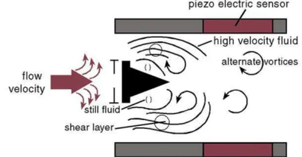
Fig. 1. Vortex flowmeter principle using piezoelectric elements
The measuring principle is based on development of Karmen Vortex shedding street in the wake of a body built into the pipeline. Vortex shedding creates alternate pressure conditions whose frequency is directly related with flow velocity, being the relationship, between these variables, given by:
. 1
d f S V
th
× ×
= (1)
0,2 < Sth < 0,21 to 300 < R < 150000
Sth – Strouhal number R – Reynolds number
B. Cantilevered-beam Configuration
Solutions for piezoelectric energy harvesting are typically based on a cantilevered-beam configuration (Figure 2). The piezoelectric beam is clamped at one end and the other end is allowed to oscillate freely in response to vibration normal to the flat surface of the beam, converting these vibrations to in-plane material strain. It is extremely important that the natural frequency of harvester configuration is tuned to match the vibration source. Vibration sources vary considerably in amplitude and dominant frequency. In most of environments, vibration is not made up of a single frequency but is typically made up of a set of main fundamental frequencies and associated harmonics. [3]
Fig. 2.Model of a cantilever-beam with piezoelectric ceramic layers
The beam dimensions and tip mass determine the resonant frequency of the beam, which is tuned to match the dominant vibration frequency of its environment. These typically small vibrations are mechanically amplified.
A development and fabrication process of a cantilever-beam with a thin film piezoelectric power generator is presented by Jeon et al. [4]
2 Main Contributions - Relationship to Cloud-based Engineering
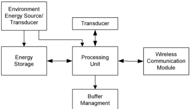
This work focuses a technological solution for power harvesting, with the aim at increasing the autonomy of low-power consumption applications. The present contribution intends to characterize a piezoelectric device as a solution to increase the energy sustainability and performance of instrumentation systems with wireless communication capabilities. This systems located in remote places have the ability to actualize information located in cloud data base computing systems. Particularly important for systems located in places where the viability of conventional energy supply is very expensive or technically difficult and it is crucial to minimize maintenance requirements. Figure 3 represents the block diagram of a sensing node with power harvesting and wireless communication capabilities.
Wireless Communication
Module Processing
Unit
Buffer Managment Transducer
Energy Storage Environment Energy Source/
Transducer
Fig. 3. Sensing node with power harvesting
3 Methodology
In this work two electrically isolated piezoelectric elements were used, whether independently or bridged for increased voltage (series configuration) or current output (parallel configuration). Series connection will double the open-circuit voltage compared to a single element, and the effective capacitance will be 1/2 of the single capacitance. Parallel connection will double the current compared to a single element configuration, and doubling the effective capacitance. The option was to use the parallel connection in order to increase the power harvesting capability. However, the single element configuration was also tested and the results are presented as a reference for analyses facility. Each solution (single and parallel connection) was assembled in a cantilever-beam configuration.
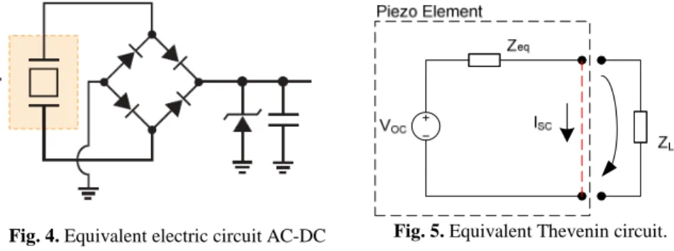
The open circuit voltage (VOC) and the short circuit current (ISC) are the two main parameters to
start this system characterization (Figure 5). Furthermore, achieving the Maximum Power Point (MPP) in function of load for different amplitude and frequency vibration is important to optimize the performance of this type of energy harvesting. To maximize transfer efficiency, the load must be matched to the piezo’s equivalent impedance. Theoretically, the piezo impedance at a given amplitude and frequency, as well as the load impedance, can be thought as a pair of simple (but unknown) impedances which make up an impedance divider. The power transfer between the two impedances is optimized when their resistive and reactive values match. This corresponds to the point at which the piezo’s loaded voltage is equal to half its open-circuit voltage.
The simplicity of the solution that is proposed intends to represent an advantage in terms of internal power consumption.
Fig. 4. Equivalent electric circuit AC-DC
converter
Fig. 5. Equivalent Thevenin circuit.
This circuit (Figure 4) is ideal for directly powering small sensors that can perform their function (e.g. record or transmit a measurement). It could also be used to extend battery life, of devices with their own battery/capacitor power source.
4 Results and Critical View
In this work the results were obtained for a established frequency of 50Hz. This frequency matches the vibration of an AC motor structure. We have also tested frequencies out of the tuned cantilever configuration, and it could confirm that, in this condition, the voltage level, and consequently the power harvesting, was extremely low. This short band wide of the cantilever with piezo elements is limitative as harvesting source and also as transducer for variables measurement. One solution to solve this problem, could be using different cantilever assembled in parallel each one tuned at a different frequency.
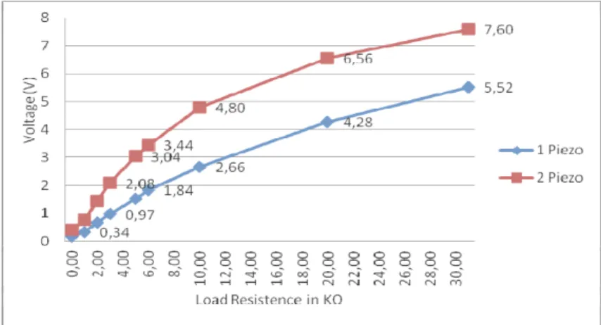
Fig. 6. Output Voltage in function of Load value
The DC output voltage (Vout) shown in figure 6 is lower than expected, due to the voltage drop in each diode (0,7V). Since low power consumption is involved, it is possible the use of Schottky diodes with voltage drops as low as 0,15V.
Fig. 7. Power harvesting in function of Load
power increase obtained corresponds to only a small increase in the output voltage. This is mainly due to the increase in current owed to parallel configuration.
Fig.8. Capacitor Voltage in function of
Vibration Amplitude with f=50Hz
Fig.9. Time of capacitor charging in function
of Vibration Amplitude with f=50Hz
The results presented in figure 8 and 9 correspond to a established frequency of 50Hz and 2 piezoelectric elements connected in parallel. The piezoelectric elements output was rectified and connected to a capacitive storage of 470 µF. The voltage at the terminals of the capacitor and the time necessary for charging are represented for different amplitudes of vibration. We can observe that the storage element subjected to the highest vibration amplitude could charge 6 times higher level of voltage during only the double-time to charge. Tests with capacitors of higher value and the same configuration of two piezo elements were done as well. Lower levels of voltage and higher period of charging were observed in this case, showing that the power harvesting is very low for storage elements with higher capacity.
Taken together these results allowed to verify that good levels of power harvesting are possible when several piezoelectric elements assembled in parallel, which may have a promising application.
5 Conclusion and further work
The piezoelectric materials are very sensitive to the surrounding vibration, producing easily very good levels of voltage. This characteristic is undoubtedly very important for vibration measurement. The use of these elements for power harvesting are however limited by the fact that the levels of voltage are not followed by good values of power supplies capabilities, exhibiting low current values. One hypothesis to solve the problem is the use of several piezoelectric elements connected in parallel. By using this method the power harvesting by piezoelectric elements can be a promising solution for low power consumption applications. Since this method can only be used in application where the environment vibration frequency has a low bandwidth, the best approach is to start by characterizing the vibration variation and the levels of power harvesting required.
References
1. Kimball, J.W., Kuhn, B.T., Balog, R.S.: A System Design Approach for Unattended Solar Energy Harvesting Supply. IEEE Transactions on Power Electronics, Vol. 24, No. 3-4, pp. 952–962, Mar.-Apr. (2009)
2. Obreja, V.V.N.: On the Performance of Commercial Supercapacitors as Storage Devices for Renewable Electrical Energy Sources. in: ICREPQ’07, Sevilla, Spain, Mar. 2007. 3. Gilbert, James M., Baloucchi, Farooq: Comparison of Energy Harvesting Systems for
Wireless Sensor Networks. in: International Journal of Automation and Computing, pp. 334-347, October 2008.