UPPER LIMB PROSTHETIC FOR
STROKE AFFECTED PATIENTS
DEBIKA KHANRA
Department of Biomedical Engineering, VIT University Vellore, Tamil Nadu-632014, India
CHAITANYA SRINIVASAN
Assistant Professor, Department of Biomedical Engineering, VIT University, Vellore, Tamil Nadu-632014, India
Abstract:
Paralysis causes loss of muscle function and loss of feeling in the affected area. The main problem faced by the patients after paralysis is muscle atrophy caused due to non-functionality of the stump. Orthotics is an orthopedic device which supports the function of the arm, leg or torso. This paper deals with the design of an upper limb orthotic device which has a hollow shell/ braces structure and can be used by paralyzed patients to bring about simple hand movements independently by the patient.
Keywords: Upper limb orthotics, Electro-mechanical arm, Arm for Paralyzed patients
1. Introduction
Stroke is a primary cause for paralysis as it causes loss of brain function, permanent damage to nerves and disturbance to blood flow.Paralysis causes loss of muscle function and loss of feeling in the affected area. The main problem faced by the patients after paralysis is muscle atrophy caused due to non-functionality of the stump. The limited functionality leads to very limited flow of oxygenated blood to the limb causing muscle wasting which is a very big medical problem. Moreover the patients become dependent on others for their basic functions or jobs which lead to serious psychological problems. An orthosis/orthoses is an orthopedic device
that supports or corrects the function of a limb or the torso.The type of orthotic limb is determined largely by the extent of effect of the stroke. Brace is an orthopedic device used to control, guide, limit and/or immobilize
an extremity, joint or body segment for a particular reason; to restrict movement in a given direction; to assist movement generally; to reduce weight bearing forces for a particular purpose; to aid rehabilitation from fractures after the removal of a cast; to otherwise correct the shape and/or function of the body, to provide easier movement capability or reduce pain. As the biological system of the hands is very highly suited for their functioning, so their man-made replacement should also involve considerable levels of complexity in both design and construction. Thus for designing orthotic limbs, it is necessary for the designer to closely examine natural limb systems and how various functions are biologically accomplished. Most importantly identify the essential performance features which have to be replicated. This will help in the precise and more accurate combination of the man-made components for at least partially recovering the lost human hand functionality. The main aim of the designers is to fabricate a product that is smooth, friction free, less power consuming for its best use by the amputees for their benefit and service.
2. Challenges Faced by Paralyzed Patients
surrounding environmental factors. The personal factor may include physical, psychological and cultural circumstance of the patient and environmental factor is related to the social, family and working condition. The adaptation level varies widely with varying factors but little is known about which factors exactly contribute to successful adjustment.
3. Materials and Method
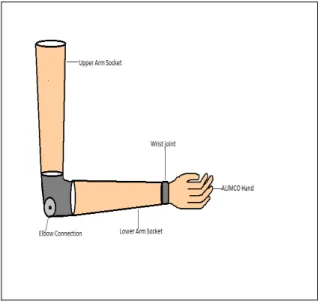
In this paper an innovative and simple design has been discussed for an upper limb orthotic device which can be used by paralyzed patients. The arm has a shell or socket like structure which can be worn by the patient and strapped on to the paralyzed arm. The whole structure consists of an upper arm socket, lower arm socket, elbow connection, wrist joint and the glove. The upper and lower arm sockets are made from polyurethane material. They are hollow in structure and has strap on one side, so that the patient can wear it easily. Colored dye can be used to give it a more cosmetic look. The elbow connection consists of a pulley on each side of the actual elbow. The glove is also made of polyurethane or elastic material which can be stretched and it can be worn just as a normal glove. The whole socket is attached to a shoulder and waist harness for providing support the paralyzed arm and for the comfort of the patient. The waist band has an on/ off switch to start and stop the hand movement. The structure of the arm can be customized according to the patients needs. It will provide support to the limp arm of the paralyzed patient and help in bringing movement to the arm. The main purpose of this hand is to give simple movements to the fingers like flexion, extension and grabbing, lifting of objects. This will give functionality to the patient’s upper limb and assist him to accomplish simple day to day activities independently.
Figure 1 – Shell of the prosthesis
4. Block Diagram Description
object which comes in between can be grabbed easily using the orthotic arm.
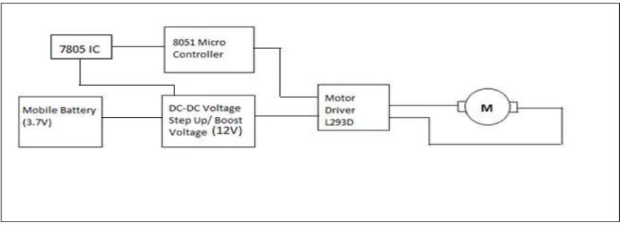
Figure 2: Block diagram of below elbow Hand Prosthetic
5. Circuit Diagram Description
The entire circuitry that is the orthotic device is power by an external power source. A mobile battery is used for this purpose which has 3.7V and 1020mAh ratings. But this voltage is not enough for driving the micro-controller and motors. So a voltage step up circuit is used for this purpose. The voltage is stepped up from 3.7V to 12V. From this 5V is obtained for the functioning of the micro-controller by using a 7805 Voltage Regulator or Zener diode of 4.8/5.1 rating. The micro-controller is programmed to control the motor movement. And 12V from the step up circuit is directly supplied to the motor driver for running the motors.
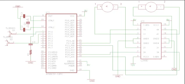
Figure 4: Circuit Diagram
Figure 5: Circuit diagram for switch controlled DC motor
In fig. 6 the circuit diagram for the voltage step up has been shown. LM2700MT step up IC is used to step up the voltage from 3.2V to 12V. The input is the voltage supply from the mobile battery. The stepped up output obtained is 12V which is then supplied to the motor driver of voltage regulator to obtain 5V for micro-controller functioning.
Figure 6: Circuit for Step-up Voltage
Result and discussion
The orthotic upper limb design for stroke affected patients discussed in this paper is simple yet helps the patient to perform some basic functions with their arm like grabbing of object and lifting it. It also brings back muscle
movement to the paralyzed patient’s hand and reduces muscle atrophy.
Acknowledgement
I would like to acknowledge the contributions made by my guide Mr. Chaitanya Srinivasan, Assistant Professor; Biomedical Division, SBST, VIT University; my friends and my family for their constant help and guidance in completion of this paper.
References
[1] Nei A. Andre, Geovany A. Borges, Francisco A. de O. (2007). A New Biomechanical Hand Prosthesis controlled by surface electromyographic signals. 29th
Annual . InternationalConference of the IEEE EMBS Cite Internationae, Lyon, Nascimento, Alexandre R.S. Romariz and Andson F. da Rocha 624-632.
[2] Saqib Ahmed, Imran Khan, Saif Ullah, J.Iqbal, Z.Riaz,“Design and Fabrication of an Efficient Automated Prosthetic Above Elbow Joint with Body Powered Gripper.”Department of Mechatronics Engineering, National University of Science and Technology (NUST) Rawalpindi, Pakistan.
[3] C.P.Mason,(1972). “Design of a powered prosthetic arm system for the above-elbow amputee” Bull. Prosth. Res.,Fall 1972. [4] S. W. Alderson, "The electric arm," in Human Limbs and Their Substitutes, Klopsteg and Wilson, Ed. New York: Hafner, 1968, pp.
359-410 (reprint of McGraw-Hill, 1954).
[5] Stephen c. Jacobsen, David f. Knutti, Richard t. Johnson, and Harold Sears; “Development of the Utah Artificial Arm”,IEEE Transactions on Biomedical Engineering, vol. BME-29, no. 4, Apri 1982
[6] Jacobsen S.C., Wood J.E. and D.F. Knutti (1984). The UTAH/ MIT dexterous hand: work in progress. The International Journal of Robotics Research,vol.4 pp.25-50
[7] Massa B., S. Roccella, M.C. Carrozza and P.Dario (2002). Design and Development of an under actuated Prosthetic Hand, 26th