ISSN 1517-7076 artigo e11828, 2017
Autor Responsável: Mateus Carvalho Data de envio: 30/06/2016 Data de aceite: 17/02/2017
10.1590/S1517-707620170002.0160
Use of green composites for manufacturing
small boats in the Amazon: numerical and
experimental evaluations
Mateus Carvalho 1, João Carlos Valente 1, Mário Xavier 1, Filipe Silva 1, José Alan Raiol 1, Leonardo Dantas Rodrigues 1, Roberto Fujiyama 1
1
Faculdade de Engenharia Mecânica, Instituto de Tecnologia, Universidade Federal do Pará – FEM/ITEC/UFPA – 66076-110, Belém, PA
e-mail: [email protected]; [email protected]; [email protected]; [email protected]; [email protected]; [email protected]; [email protected]
ABSTRACT
The Amazon has a great potential of natural resources. There is a wide diversity of plant specimens and many of them can be extracted and processed such as jute, sisal and mauve fibers. It is known that usualy small communities from Amazon build their boats using a rudimentary and ecologically incorrect method, which comes from brazilian natives. This method consists in cut of trees with large trunks, which are burned and scraped until they get the desired shape. This process is not viable due to the long time spent and also it is environmentally unacceptable nowadays. Considering these facts, it was created a project at UFPA aiming to evaluate the building viability of small boats adapted to the Amazon region. These boats have been made with composite material, polymeric resin reinforced with natural fiber fabric. Hence, this paper brings the first stage of this project, treating on the build of a small boat with reduced dimensions. This prototype was experimentally studied, using strain gages, and evaluated numerically by finite element method through the software ANSYS®. This stage was very important to optimize the parameters used in the finite element model, which was employed to analyse the model with real dimensions. As a result, the numerical models showed a good compatibility with real tests. Additionally, the designed boat demonstrated to be able to hold the imposed loads.
Keywords: Green composites, Numerical and Experimental Analysis, Small boats.
1. INTRODUCTION
Regarding the Amazon, the fluvial navigation has specific characteristics due to some natural factors, such as continental extension, inadequate weather, and ground for construction of highways and railroads, becoming the naval construction a regional necessity. The traditional process of manufacturing boats comes from the knowledge of brazilian natives. It consists in cut of trees with large trunks, which are later burned and scraped until the small boats be shaped. Nowadays, these skills still can be seen in communities, where people have an innate ability of building ship and fluvial navigation, as shown in Fig. 1.
The interest in composite materials reinforced by natural fibers has increased, mainly due to the sustainability, as typically occurs with green composites which are being strongly studied in the last two decades, specially in the automotive industry [13]. Another reason is the wide range of possibilities in modeling and obtainment of parts designed with environmental endorsement.
The composite materials are a class of materials that have superlative properties in comparison with isotropic materials (metals, ceramic and polymers), considering high resistance and low weight [12]. Although aluminum and synthetic fiber boats are a good option for this sort of transportation, it still has a high manufacturing cost. This fact consolidates the idea of developing boats able to comply the necessity of communities around Belém city, as well as contributes to overcome cost issues.
For this investigation, natural jute fiber was chosen due to its good mechanical properties and also its easiest conformability. It is noteworthy that the jute is a natural fiber of the Tilioideae family, abundantly found in tropical weathers as occurs in the Amazon.
A prototype with reduced dimensions was designed. In this case, a boat with 730 mm length with a hull of two layers of jute fabric along the polyester resin was made. While the small prototype was being developed, five specimens with the same characteristics and mechanical properties were produced, and these specimens were submitted to tensile tests to evaluate the mechanical properties. The shape and dimensions of the specimens followed the ASTM D3039 standard. After this characterization, the boat was tested using strain gages, which allowed the assessment of the stresses along the entire boat.
For the numerical analysis, the boat with the same dimensions were designed using the software SolidWorks® and later tested using ANSYS®.
2. GEEN COMPOSITES
Green composites have been developed to address the sustainability issues of non-renewable resource based materials. These composites are often produced by reinforcing natural fibers in petroleum based thermoset resins or thermoplastic polymers. Thermoplastic polymers from renewable resources are commercially available, whereas thermoset resins are predominantly derived from crude oil resources. Cellulose fibers have significant importance and potential for polymer reinforcement in lightweight composites. [4]
The Amazon has a great diversity of fibrous vegetation, such as jute, sisal, palm and mauve fibers, which are the most used ones, mainly in the textile industry. However, recent investigations have shown that some of these fibers have good mechanical properties, justifying its use for structural purposes. [5, 7, 8, 11]
For about nine years, UFPA Laboratory of Composite Materials has been performing the characterization of several fibers abundantly found in the region. Some works include the production of composites from polymeric resin and natural fibers such as bamboo, sisal, jute and mauve [3], the aspects of fracture [6] and the feasibility of its application in some sectors, such as architecture and the replacement of metal alloys in aviation. [2] Table 1 provides an overview of some natural fibers and their properties.
Table 1: Summary of some fiber properties. [1]
FIBER DENSITY (kg/m³) YOUNG’S MODULUS (GPa) TENSILE STRENGTH (MPa)
Jute 1440 – 1520 35 - 60 400 - 860
Sisal 1400 – 1450 10 - 25 550 - 790
Coir 1150 - 1220 4 - 6 135 - 240
Cotton 1520 - 1560 7 - 12 350 - 800
Flax 1420 - 1520 75 - 90 750 - 940
Ramile 1450 - 1550 38 - 44 500 - 680
Bamboo 600 - 1100 11 - 32 140 - 800
3. BOAT BUILDING
computational conditions used in the numerical model.
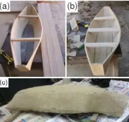
First of all, a boat using miriti was built. It is worth note that miriti is a very low density wood, and easy to cut and get shape. This boat was used as mold to laminate the two layers of composite. Two days later the prototype was removed and the jute composite boat was ready for testing. Figure 2 shows some of prototype manufacturing steps.
Figure 2: Prototype manufacturing steps: (a) molding the boat; (b) miriti boat finished; (c) covering the boat with jute fiber.
This procedure has caused some difficulties in lamination, providing finishing problems and even irregularities in the curing of the resin in some parts, resulting in non-uniformity in the mechanical properties. This was mainly due to the need of protect the mold with a plastic layer resistant to high temperatures, which was generated in the reaction process of polyester mix. Furthermore, the prototype showed several points of leakage, which only became evident during the tests and could not be satisfactorily repaired. The original intention of the protection was to use the same mold to build several prototypes. However, as the construction of miriti model was simplest than imagined initially, the building methodology used in the subsequent steps was changed. Several miriti models were built and "sandwich laminations" were made, inside and outside the miriti model. Thus, there is a significant improvement in the lamination time in the finishing quality and uniformity of mechanical properties. Besides the great advantage to improve the float-age of the boat due to the density of miriti be much lower than that of water.
4. MATERIALS AND METHODS
At UFPA’s Mechanical Engineering Laboratory there is no apparatus for performing bending tests, tensile, compression and torsion on the prototype, which are the efforts that the boat may be submitted (individually or simultaneously) depending on the sailing conditions. Therefore, simple tests had to be carried out: bi-supported boat with distributed internal load and with the prototype in water and subjected to a distributed load.
4.1 Bi-supported boat with distributed internal load
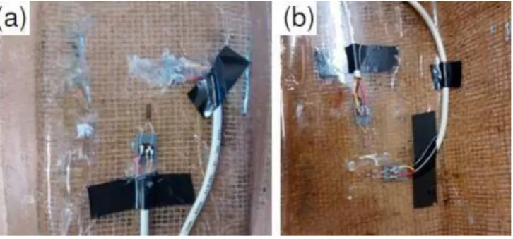
Figure 3: Strain gages installed and protected at the center area: (a) outer; (b) inner.
Figure 4b shows the boat during the evaluation of strains. The space between the supports was 580 mm, it is the total length of the bottom of the boat.
Figure 4: Boat during the tests with strain gages: (a) data logger VISHAY® D4; (b) strains evaluation of the bi-supported boat.
4.1.1 Numerical model
The model was assessed with the software ANSYS®. The meshes were done using element sizes of 2.5 mm on the semi plan faces, 1 mm on the bended faces and 0.33 mm to the thickness faces. The composite mechanical properties were obtained from tensile tests: Young’s modulus, 2.0 GPa and Poisson’s ratio, 0.39. The total mesh has 222,293 elements and 409,778 nodes. Because of its symmetrical behavior, the model was made with one quarter of symmetry to reduce computational costs. In other words, only one quar-ter of the boat was designed and constrains were applied to make a symmetrical behavior. Paths (a software tool) were created along the structure with the same orientation of strain gages.
The load conditions were done using a distributed force on the bottom inner face with the same value of the weight of sand inside the boat. Frictionless supports were used on the symmetry faces and also the restriction displacement for the y axis on the longitudinal inferior limit was used. Figure 5 shows the total mesh, the paths and the loads.
Figure 5: (a) Mesh. (b) Paths. (c) Loads.
4.2 Boat on the water
which prevented the realization of load tests properly. Figure 6 shows the steps of performing the load test.
Figure 6: (a) Preparation of the argil mass; (b) Measurement with the empty boat; (c) Measurement with a distributed mass of 2 kg.
Although the efforts during the lamination and the test preparation, the test was not completely well succeeded due to the entering of water in the boat, so, it was not possible to know the real load. Besides that, the strains were constantly changing, and the boat could not remain properly on the water for a long time. However, suitable strain measurements where carried out when the boat was empty, allowing the validation of the numerical model.
4.2.1 Numerical model
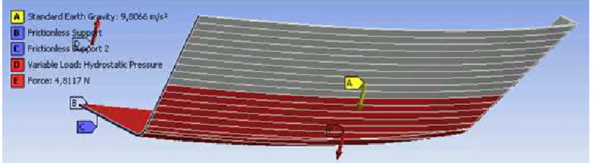
The mesh and paths of this model were the same of bi-supported boat by the longitudinal limits. Hydrostatic pressures with deeps of 15 mm (for empty boat), 20 mm and 40 mm were used as loads. Further, a representative force of the mass inside the boat and frictionless supports on the faces of the thickness were also considered. These faces were plans of symmetry. Moreover, forces representing masses of 0.93, 1.86, 2.79 and 3.72 kg were placed inside the boat to evaluate its behavior according to the reaction of the water. To discover the height of water an iterative process was made using the design of the boat. Figure 7 shows the loads. The determination of the force was made by means of the resource displacement putted on the
inner face of the boat, and then the post processing resource called force reaction was performed. That reaction was used to the force mentioned before and the analysis was carried out once again.
Figure 7: Load conditions for the boat on the water.
5. RESULTS AND DISCUSSIONS
Table 2: Real and numerical strains for the bi-supported boat.
MASS INSIDE THE BOAT (kg)
OUTER TRANSVERSAL INNER TRANSVERSAL
REAL (με) NUMERICAL (με) REAL (με) NUMERICAL (με)
0.93 -37 -41 -8 38
1.86 -86 -83 31 77
2.79 -134 -124 88 116
3.72 -175 -165 134 152
The bi-suported boat numerical model behaved in a linear way, with the strains changing linearly according to the load applied. Table 2 and Figure 8 shows the good linearity of the model in terms of strains and applied load. The presence of bilinear tensile behavior [9] must be analysed in future investigations.
Figure 9a shows the field of transversal strains on the bottom of the hull for a load of 3.72 kg. It is possible to realize that the strains are not so large taking into account that the Young modulus is 2 GPa, and the greatest strain is 1052 µe. The stresses show that the boat can bear these loads with a great safety factor. The maximum stress shown is 2.3 MPa (Fig. 9b) and the ultimate compressive strength of the material is 32 MPa. In other words, the ultimate compressive strength is more than fourteen times the value of maxi-mum stress.
Figure 9: Maximum principal (a) strains and (b) stresses on the bottom of the hull. Boat bi-supported with 3,72 kg inside it.
Figure 10: Directions of principal stresses for the boat: (a) 20 mm into the water. (b) 40 mm into the water.
As previously mentioned, it was not possible to perform load tests properly because of leaks on the boat. However, the test performed only with the own weight of the boat served to realize that the numerical conditions are suitable. Table 3 presents the experimental and numerical results for the points where the strain gages were installed. Note that the values yield a reasonable agreement.
Table 3: Experimental and numerical strain results to the empty boat in the water.
STRAIN GAGE EXPERIMENTAL (με) NUMERICAL (με)
Inner longitudinal -38 -13
Inner transversal 84 77
Outer longitudinal 9 -26
Outer transversal -91 -68
Figure 11: Maximum principal (a) strains and (b) stresses on the bottom of the hull. Boat on the water carrying 3,72 kg weight.
Figure 12 shows the transversal strains along the longitudinal line of the boat on the water. Note that the boat is more loaded on its center, and the strains are decreasing towards the longitudinal limits of the boat.
Figure 13 shows the longitudinal strains also along the longitudinal line of the boat. The results for the longitudinal strains are different to the transversal strains. The lines of the graph are not mirrored for the inner and outer strains.
Figure 13: Longitudinal strains along the longitudinal line for the boat on the water: (a) outer and (b) inner.
With these evaluations it is possible to realize the great strength of the boat, taking into account its own weight and the total external load applied. The load of approximately 3.72 kg makes the boat with 100 mm height submerge 60 mm in the water. The heaviest loads that the boat received were not enough to make the structure fail. The stresses were much lower than the limit of strength of the composite material used on the boat. By means of analytical calculations, was noticed that the maximum weight carried by the boat before submerge completely in the water is around 7 kg. So, 3.72 kg is a good safety limit because is approximately half of the weight that boat can carry and it is five times the weight of the boat. Therefore, it is reasonable to affirm that the boat is light and strong compared to wooden boats.
6. CONCLUSION
In this investigation a small size boat prototype was made with jute fiber reinforced polymeric matrix. This prototype was instrumented with strain gages and evaluated in different loads situations. The measurements were used to validate the numerical model.
The following step was the validation of the computational model. This situation has demanded more careful with the boundary conditions used on the model. For this experiment, there is a reasonable proximity between both numerical and experimental results, yielding good physical consistency.
The great advantage of the numerical model is the possibility of the global visualization of the stresses and strains existing in the boat, as well as the simulation of different loading conditions.
Another important observation is the magnitude of stresses and strains generated on the boat to be lower than the limits obtained in mechanical tests for the same material, even under big loadings.
7. BIBLIOGRAPHY
[1] ASHBY, M.F., Materials and the environment: eco-informed material choice, 2 ed., Oxford, Butter-worth-Heinemann, 2012.
[2] BARROS, M.A.S., Vantagens da Aplicação de Material Compósito em Substituição as Ligas Metálicas na Aviação, Dissertação de M.Sc., UFPA, Belém, PA, Brasil, 2014.
[3] CARVALHO M.J.C., Caracterização de Materiais Compósitos de Matriz Poliéster Reforçada por Fibras Vegetais Continuas e Alinhadas, Dissertação de M.Sc., UFPA, Belém, PA, Brasil, 2014.
[4] DICKER, M.P.M, DUCKWORTH, P.F., BAKER, A.B., et al., “Green Composites: A review of materials attributes and complementary applications”. Composites Part A: Applied Science and Manufacturing, v. 56, pp. 280-289, Jan. 2014.
[5] DITTENBER D.B., GANGARAO H.V.S., “Critical review of recent publications on use of natural com-posites in infrastructure”, Comcom-posites Part A: Applied Science and Manufacturing, v. 43, pp. 1419–1429, Aug. 2012.
[6] KUWAHARA, M., Compósitos de Poliéster Reforçados por Fibras de Bambu e Sisal: Características Mecânicas e Aspectos Fratográficos, Dissertação de M.Sc., UFPA, Belém, PA, Brasil, 2013.
[7] KORONIS G., SILVA A., FONTUL M., “Green composites: a review of adequate materials for autom o-tive applications”, Composites Part B: Engineering, v. 44, pp. 120-127, Jan. 2013.
[8] LA MANTIA F.P., MORREALE M., “Green composites: a brief review”, Composites Part A: Applied Science and Manufacturing, v. 42, pp. 579–588, Jun. 2011.
[9] MANCUSO, A., PITTARESI, G., TUMINO, D., “Mechanical Behaviour of a Green Sandwich Made of Flax Reinforced Polymer Facings and Cork Core”, Procedia Engineering, v. 109, n. 2, pp. 144-153, Feb. 2015.
[10] MARSH, G., “Material trends for FRP boats”, Reinforced Plastics, v. 47, n. 9, pp. 23-34, Oct. 2003. [11] MEDINA, J.C., Plantas Fibrosas da Flora Mundial, 2 ed., Campinas, Instituto Agronômico de Campi-nas, 1959.
[12] RIBEIRO, J.L.P., GREGORI, M.L., PARDINI, L.C., “Prediction of elastic properties of thermo struct u-ral composites with multidirectional reinforcement”, Revista Matéria, v.13 n.1, pp. 33-48, Rio de Janeiro. 2008.

![Table 1: Summary of some fiber properties. [1]](https://thumb-eu.123doks.com/thumbv2/123dok_br/18874801.421081/2.892.166.751.825.1007/table-summary-fiber-properties.webp)