ISSN 0104-6632 Printed in Brazil
www.abeq.org.br/bjche
Vol. 30, No. 02, pp. 355 - 367, April - June, 2013
Brazilian Journal
of Chemical
Engineering
PARAMETRIC STUDY OF HYDROGEN
PRODUCTION FROM ETHANOL
STEAM REFORMING IN A MEMBRANE
MICROREACTOR
M. de-Souza, G. M. Zanin and F. F. Moraes
*Departamento de Engenharia Química, Universidade Estadual de Maringá, Av. Colombo 5790, Bloco D-90, ZIP 87080-900, Phone: +(55) (44) 3011-4754, Maringá – PR, Brazil.
E-mail: [email protected]; [email protected] E-mail: [email protected]
(Submitted: February 5, 2012 ; Revised: May 22, 2012 ; Accepted: July 13, 2012)
Abstract - Microreactors are miniaturized chemical reaction systems, which contain reaction channels with characteristic dimensions in the range of 10-500 μm. One possible application for microreactors is the conversion of ethanol to hydrogen used in fuel cells to generate electricity. In this paper a rigorous isothermal, steady-state two-dimensional model was developed to simulate the behavior of a membrane microreactor based on the hydrogen yield from ethanol steam reforming. Furthermore, this membrane microreactor is compared to a membraneless microreactor. A potential advantage of the membrane microreactor is the fact that both ethanol steam reforming and the separation of hydrogen by a permselective membrane occur in one single microdevice. The simulation results for steam reforming yields are in agreement with experimental data found in the literature. The results show that the membrane microreactorpermits a hydrogen yield of up to 0.833 which is more than twice that generated by the membraneless reactor. More than 80% of the generated hydrogen permeates through the membrane and, due to its high selectivity, the membrane microreactor delivers high-purity hydrogen to the fuel cell.
Keywords: Bioethanol; Microchannel reactor; Modeling; PEM fuel cells; Portable devices.
INTRODUCTION
The fast evolution of multifunctional portable devices leads to increasing consumption of electrical power, and providing sufficiently long-lasting power sources for portable devices (such as laptops and cell phones) becomes more and more challenging, even when a modern lithium-ion battery is used. The higher power consumption contributes to environ-mental pollution arising from the mass disposal of expended batteries. Long-life batteries offering high efficiency and reduced environmental impact are therefore in demand. Hydrogen-based proton exchange membrane fuel cells (PEMFCs) seem
356 M. de-Souza, G. M. Zanin and F. F. Moraes
Brazilian Journal of Chemical Engineering
ethanol systemsoffer only relatively low power density due to methanol/ethanol crossover through the polymer electrolyte membrane and the low reaction rate of fuel oxidation over the anode electro-catalyst. On the other hand, on-board reforming systems generate electric energy in fuel cells from hydrogen by steam reforming, for example, from ethanol (Aicher et al., 2009; Aravamudhan et al., 2005; Deshmukh and Vlachos, 2005; Palo et al., 2002; Sordi et al.,2009; Yao et al., 2006).
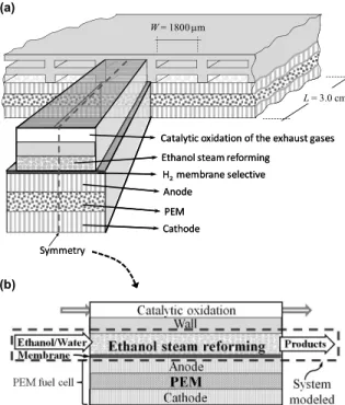
We propose to explore the use of a microchannel reactor to produce hydrogen by the reaction of ethanol with water. The schematic of our proposed fuel processor is shown in Fig. 1 (a). It should have the following three main components: (1) catalytic oxidation of the exhaust gases produced in the ethanol steam reforming channel for providing the energy required by the reforming reaction; (2) ethanol steam reforming with particles of Ni/Al2O3
(catalyst) and a palladium micromembrane for hydrogen separation; (3) PEMFC, which consumes the produced hydrogen as it crosses the membrane. This paper will focus on the modeling of a palladium based membrane microreactor for hydrogen separa-tion as well as steam reforming of the ethanol in a fixed bed microchannel (shown in Fig. 1 (b)).
Catalytic oxidation of the exhaust gases Ethanol steam reforming
H2 membrane selective
Anode PEM Cathode Symmetry
W= 1800 μm
L= 3.0 cm
(a)
(b)
(a)
(b)
Catalytic oxidation of the exhaust gases Ethanol steam reforming
H2 membrane selective
Anode PEM Cathode Symmetry
W= 1800 μm
L= 3.0 cm
(a)
(b)
(a)
(b)
Figure 1: Schematic representation of the micro-fuel
processor: (a) 3-D representation, (b) 2-D symmetry indicating the system modeled.
Ethanol Steam Reforming
Ethanol steam reforming is the cheapest and most efficient way to produce hydrogen from biomass. Both reactants (water and ethanol) contain H atoms which contribute to the hydrogen yield and, furthermore, ethanol is nontoxic and easy to store and transport (Fatsikostas and Verykios, 2004; Iulianelli et al., 2009; Kawamura et al., 2006; Mariño et al., 2001; Sun et al., 2005). This technology is particularly interesting for a country such as Brazil, which is one of the largest ethanol producers and exporters in the world and where ethanol from sugarcane is produced at extremely competitive prices. Its daily 2006 production exceeded 300 000 barrels (Hotza and Costa, 2008). Stoichiometrically, the overall ethanol steam reforming reaction can be represented as follows:
2 5 2 2 2
C H OH 3H O+ R 2CO 6H+ (Reaction 1) However, there are several reaction pathways that can occur in the ethanol steam reforming process, depending on the catalyst and the operating conditions. Therefore, the selectivity for hydrogen is affected by many undesirable side reactions (Haryanto et al., 2005; Vaidya and Rodrigues, 2006). Ni catalysts with alumina support have relatively low cost and have been reported to be very active and selective for ethanol steam reforming (Fatsikostas and Verykios, 2004; Mariño et al., 2001; Therdthianwong et al., 2001). Comas et al. (2004b) have investigated ethanol steam reforming based on Ni/Al2O3 catalyst.
The reactor was made with a Pyrex glass tube of 12 mm inner diameter. The experiments were performed under the following conditions: catalytic mass: 0.105–0.840 g; temperature: 573–773 K; total feed rate: 210 ml/min; ethanol molar fraction: 0.017; water/ethanol molar ratio: 1–6. They proposed that good steam reforming performance is established at a temperature of 773 K and then occurs according to the reaction C2H5OH + H2O → CH4 + CO2 + 2H2
followed by methane steam reforming. At this temperature (773 K) they used a space time of up to 4 gcat min/l (8.95×10⁵ gcats/molEtOH) and a water/
ethanol ratio of 3.3. The main products obtained were CO, CO2, CH4 and H2.
Parametric Study of Hydrogen Production from Ethanol Steam Reforming in a Membrane Microreactor 357 the catalysts used for ethanol steam reforming
produce CO at concentrations limited by thermody-namic balance, and the reforming process alone is insufficient to reach the allowed level of CO. Thus, purification methods are necessary to remove CO present in the product flow of the reformer (Sordi et al., 2009), such as preferential oxidation of the carbon monoxide in a PrOx reactor, pressure swing adsorption, cryogenic distillation or membrane technology in which ~99.9% pure of hydrogen can be produced.
Microreactors
The use of microreactors for in-situ and on-demand chemical processing is gaining increasing importance in the chemical industry. Microreactors have characteristic properties, like a high surface to volume ratio, the use of small amounts of chemicals, high heat and mass transfer rates, and short residence times that make these devices a research topic of high interest. Microreactors have been proposed for various applications, such as intrinsic kinetic studies, catalyst screening, fine-chemical synthesis, and in launching fuel cells systems for portable power generation (Hu et al., 2003; Löwe and Ehrfeld, 1999; Wörz et al., 2001). The microreformer fuel cell combination has the advantage of avoiding the tedious charging cycles needed by conventional rechargeable lithium-ion batteries. Also, the energy storage density per unit weight of this system is higher than that of batteries (Palo et al., 2002; Pattekar et al., 2001; Terazaki et al., 2005). Thus, less frequent recharging in terms of refilling with ethanol fuel is necessary. Membrane microreactors are an important class of microreactors that combine reaction and separation in one single device. Thus, for example, a thin palladium membrane can be included which separates hydrogen from the reformate gas mixture (Alfadhel and Kothare, 2005; Assaf et al., 1998; Karnik et al., 2003). Assaf et al. (1998) modeled the methane steam reforming in an isothermal membrane reactor and concluded that the membrane reactor, besides providing purified hydrogen still presents a higher methane conversion yield than the conventional fixed-bed reactor. This work presents a two-dimensional mathematical model of an isothermal membrane microreactor operating under steady-state conditions for use as a source of pure hydrogen for a PEM fuel cell from ethanol steam reforming catalyzed by Ni/Al2O3. The
model aims at simulating the behavior of a membrane microreactor, so the yield improvements in relation to a membraneless fixed-bed microreactor
are compared and discussed. The complete mem-brane microreformer fuel cell unit can be considered to be a promising alternative to conventional sources of energy due to its ability to provide an uninterruptible power supply as long as ethanol and water are provided.
MODEL DEVELOPMENT
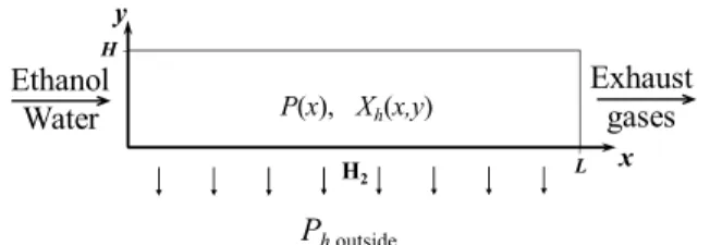
For ethanol steam reforming, a catalytic fixed-bed microreactor is fed with a gas mixture of ethanol and water in a water/ethanol molar ratio of 3.3. The reactor consists of several microchannels (in sufficient quantity as to be able to assume that the system behaves as the bidimensional system as shown in Fig. 2) with a height of H = 5×10⁻⁴ m, width of W = 1.8×10⁻³ m and length of L = 3.0×10⁻² m The computational domain employed in this study consists of a single rectangular channel (Figure 2) in steady-state conditions, isothermal operation and the fluid is assumed to be an ideal gas mixture that follows Dalton’s law. The microreactors allow fast heat transfer due to their thin wall thicknesses and thus the reaction is maintained at an optimal operating temperature (Löwe & Ehrfeld, 1999). The energy required for performing an endothermic reaction can be supplied via an exothermic reaction, whose coupling can be achieved by operating endothermic and exothermic reactions in parallel microchannels (Deshmukh & Vlachos, 2005). The model investigated in this study is a membrane microreactor, where a hydrogen-permselective membrane substitutes one of the solid walls of the microchannel. We studied space times (τ = wcat/Fe0)
ranging from 0.75×10⁵ to 2.24×10⁵ gcat s/mol
(corresponding to 0.335 to 1 gcat min/l).
H2
y
x H
L
Ethanol Water
Exhaust gases
Ph,outside
P(x), Xh(x,y)
Figure 2: Schematic representation of the
micro-channel reactor modeled.
Ethanol Steam Reforming Kinetics
The reaction pathway proposed for ethanol steam reforming catalyzed by Ni/Al2O3 was based on the
358 M. de-Souza, G. M. Zanin and F. F. Moraes
Brazilian Journal of Chemical Engineering
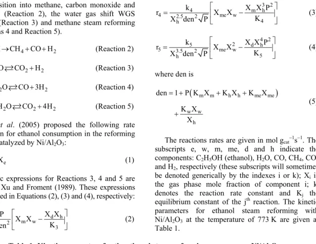
decomposition into methane, carbon monoxide and hydrogen (Reaction 2), the water gas shift WGS reaction (Reaction 3) and methane steam reforming (Reactions 4 and Reaction 5).
2 5 4 2
C H OH →CH +CO +H (Reaction 2)
2 2 2
CO H O + R CO H+ (Reaction 3)
4 2 2
CH +H O RCO +3H (Reaction 4)
4 2 2 2
CH +2H O RCO +4H (Reaction 5) Sun et al. (2005) proposed the following rate expression for ethanol consumption in the reforming process catalyzed by Ni/Al2O3:
2 2 e
r =k PX (1)
Kinetic expressions for Reactions 3, 4 and 5 are given by Xu and Froment (1989). These expressions are reported in Equations (2), (3) and (4), respectively:
3 d h
3 2 m w
3 h
k P X X
r X X
K X den
⎡ ⎤
= ⎢ − ⎥
⎣ ⎦ (2)
3 2
4 m h
4 2.5 2 me w
4 h
k X X P
r X X
K X den P
⎡ ⎤
= ⎢ − ⎥
⎣ ⎦ (3)
4 2
2
5 d h
5 3.5 2 me w
5 h
k X X P
r X X
K X den P
⎡ ⎤
= ⎢ − ⎥
⎣ ⎦ (4)
where den is
(
m m h h me me)
w w
h
den 1 P K X K X K X K X
X
= + + +
+
(5)
The reactions rates are given in mol gcat−1s−1. The
subscripts e, w, m, me, d and h indicate the components: C2H5OH (ethanol), H2O, CO, CH4, CO2
and H2, respectively (these subscripts will sometimes
be denoted generically by the indexes i or k); Xi is
the gas phase mole fraction of component i; kj
denotes the reaction rate constant and Kj the
equilibrium constant of the jth reaction. The kinetic parameters for ethanol steam reforming with Ni/Al2O3 at the temperature of 773 K are given at
Table 1.
Table 1: Kinetic parameters for the ethanol steam reforming process over Ni/Al2O3.
Symbol Expression* Value at T = 773 K
k2 a
5
4.55 10 2030 exp
T T
−
× ⎛− ⎞ ⎜ ⎟
⎝ ⎠ 4.26×10−
9 mol Pa−1g cat−1s−1
k3 b
3 8074.33
5.43 10 exp T
− ⎛− ⎞
× ⎜ ⎟
⎝ ⎠ 1.58×10−
7
mol Pa−1gcat−1s−1
k4 b
14 28879
3.711 10 exp T − ⎛ ⎞ × ⎜ ⎟
⎝ ⎠ 2.21×10−
2
mol Pa0.5gcat−1s−1
k5 b 13
29336.1 8.960 10 exp
T − ⎛ ⎞ × ⎜ ⎟
⎝ ⎠ 2.95×10⁻³ mol Pa0.5gcat−1s−1
K3 b
4400 exp 4.036
T
⎛ − ⎞ ⎜ ⎟
⎝ ⎠ 5.239
K4 b
10 26830
1 10 exp 30.114 T
−
⎛ ⎞
× ⎜ + ⎟
⎝ ⎠ 1.01×10⁸ Pa2
K5 b K3 K4 5.29×10⁸ Pa
2
Km b
10 8497.71
8.230 10 exp T
− ⎛ ⎞
× ⎜ ⎟
⎝ ⎠ 4.89×10−
5
Pa−1
Kme b
9 4604.28
6.640 10 exp T
− ⎛ ⎞
× ⎜ ⎟
⎝ ⎠ 2.56×10⁻⁶ Pa−1
Kh b
14 9971.13
6.120 10 exp T
− ⎛ ⎞
× ⎜ ⎟
⎝ ⎠ 2.45×10−
8
Pa−1
Kw b
5 10666.35
1.770 10 exp T −
⎛ ⎞ × ⎜ ⎟
⎝ ⎠ 1.80×10−
1
* Temperature in Kelvin a
Taken from Sun et al. (2005) b
Parametric Study of Hydrogen Production from Ethanol Steam Reforming in a Membrane Microreactor 359 In this work, these kinetic expressions were used
for a parametric study with the kinetic parameters of Sun et al. (2005) and Xu and Froment (1989) given in Table 1.
Models and Boundary Conditions
According to Pattekar and Kothare (2002), a rigorous partial differential equation for modeling mass, momentum and energy balances is better suited for microreaction systems than empirical approaches which are often applied for modelling conventional large-scale processes. Thus, transport phenomena in an isothermal microchannel reformer can be described by the conservation equations of mass and momentum leading to a set of non-linear partial differential equations. The microchannel filled with catalyst particles forms a porous medium and thus Darcy's law will be considered for the flow across the micro-packed bed:
p K (u, v) P
= = − ∇
μ
u (6)
where u is the fluid flow velocity vector; P denotes the pressure; μ denotes the dynamic viscosity of the fluid and Kp the permeability of the porous media,
which can be estimated by the expression: 2 3
p
p 2
d K
150(1 )
ε =
− ε (7)
in which ε is the porosity of the bed and dp is the
catalyst particle diameter. This method of calculating Kp provides an estimation of the actual value varying
according to the catalyst packing conditions (Pattekar and Kothare, 2004). The steady-state mass conservation balance combined with Eq. (6), the molar equation of continuity and the ideal gas law leads to:
(
)
6 5
p
ij j 2 4 5
g i 1 j 2
K P
. P r 2 r r r
R T = =
⎛ ⎞
∇ −⎜⎜ μ ∇ =⎟⎟ ν = + +
⎝ ⎠
∑∑
(8)where Rg is the universal gas constant, T the
temperature; i represents any of C2H5OH, H2O, CO,
CH4, CO2 and H2; j indicates the chemical reaction
(Reaction 2, 3, 4 or 5) and νij is the stoichiometric
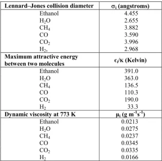
coefficient of component i in the jth reaction. The local dynamic viscosity is established based on the Chapman–Enskog theory for multi-component gas mixtures at low density (Bird et al., 2004):
5
i i 5
i 1 k ik
k 1 X
(X )
= =
μ μ =
Φ
∑∑
(9)with the Chapman–Enskog parameter:
2
1/2 1/2 1/4
i i k
ik
k k i
1 M M
Φ 1 1
M M
8
− ⎡ ⎤
⎛ ⎞ ⎢ ⎛ ⎞ ⎛μ ⎞ ⎥
= ⎜ + ⎟ +⎜ ⎟ ⎜μ ⎟
⎢ ⎥
⎝ ⎠ ⎣ ⎝ ⎠ ⎝ ⎠ ⎦ (10)
where Mi denotes the molecular weight and μi the
dynamic viscosity of an individual component. The values of μi for the substances used in this work are
given at Table 2.
Table 2: Properties of the species (Perry et al., 1997).
Lennard–Jones collision diameter σi (angstroms)
Ethanol 4.455
H2O 2.655
CH4 3.882
CO 3.590
CO2 3.996
H2, 2.968
Maximum attractive energy
between two molecules єi/K (Kelvin)
Ethanol 391.0
H2O 363.0
CH4 136.5
CO 110.3
CO2 190.0
H2 33.3
Dynamic viscosity at 773 K μi (g m-1s-1)
Ethanol 0.0213
H2O 0.0275
CH4 0.0237
CO 0.0345
CO2 0.0335
H2 0.0166
The boundary conditions are described as follows:
At the microchannel inlet boundary (x = 0):
p o
K P u
x
∂
= − μ ∂ , and v = 0, 0 ≤ y ≤ H
At the microchannel outlet boundary (x = L):
P = Pout , 0 ≤ y ≤ H
At the microchannel superior boundary (y = H):
P 0 y
∂ =
360 M. de-Souza, G. M. Zanin and F. F. Moraes
Brazilian Journal of Chemical Engineering
At the microchannel inferior boundary (y = 0):
p p
k P v
y
∂
= − μ ∂ , 0 ≤ x ≤ L ,
This last condition is due to permeation through the permselective membrane, in which vp (m/s) is the
velocity of the fluid as it diffuses through the membrane (drift velocity) and kp is the permeability
of the membrane. Alfadhel and Kothare (2005) and Karnik et al. (2003) defined vp as follows:
(
)
q q hp h,outside
p g
g h
PX P
k E
v exp R
R T PX
⎛ ⎞
⎛ − ⎞ ⎜ − ⎟
= δ ⎜⎜ ⎟⎟ ⎜ ⎟
⎝ ⎠ ⎝ ⎠ (11)
where δ is the membrane thickness and Ph,outside is the
partial pressure of the hydrogen outside of the membrane. Karnik et al. (2003) evaluated a 0.2 μm thick Pd membrane and obtained E = 4 077.2 J/mol, kp = 4.15×10⁻⁶ mol K/(m Pa0.489s) and q = 0.489.
Because the hydrogen that crosses the membrane is immediately consumed by PEMFC, it is assumed that Ph,outside << PXh ; then:
(
)
-5
p 0.511
h
3.45 10 490.4
v exp
T PX
× ⎛ ⎞
= ⎜− ⎟
⎝ ⎠ (12)
The steady-state mass conservation equation for the individual gas-phase species is
ef,i i i
g g
5
cat ij j
j 2
P P
X X
R T R T
(1 ) r , i e, w,..., h
=
⎡ ⎛ ⎞ ⎤
∇⋅⎢ ∇ −⎜⎜ ⎟⎟+ ⎥=
⎢ ⎝ ⎠ ⎥
⎣ ⎦
ρ − ε
∑
ν =u D
(13)
where ρcat is the catalyst mass per unit of volume, ε
is the porosity of the media and 32
ef ,i = εi
D D is the effective concentration-driven diffusion coefficient of the specie i, in which Di is expressed in terms of
binary diffusion coefficients:
i
i n
i k 1, k i
ik 1 X
X D
= ≠
− =
∑
D (14)
The Dik values are obtained from the Chapman–
Enskog theory:
3
i k
4
ik 2
ik ik 1 1 T
M M
D 5.9543 10
Pσ Ω
−
⎛ + ⎞
⎜ ⎟
⎝ ⎠
= × (15)
in which σik and Ωik are, respectively, the Lennard–
Jones collision diameter and collision integral between one molecule of i and one molecule of k. This equation is given by Bird et al. (2004). In this work the constant in Eq. (15) was recalculated to give Dik in the units of m2/s, and, for this, the
pressure, in Pa, and Mi in kg/mol, were used. The
collision diameter is obtained from σik = 1/2(σi + σk)
and Ωik is taken from Neufeld et al. (1972).
(
)
(
)
(
)
ik 0.15610
ik ik
ik ik
1.06036 0.19300 exp 0.47635 1.03587 1.76474 exp 1.52996 exp 3.89411
Ω = + τ +
τ
+
τ τ
(16)
in which τik = KT/εik is the dimensionless
temperature, where K is the Boltzmann constant and
ik i k
ε = ε ε is the maximum attractive energy
between one molecule of i and one molecule of k. The values of σi and εi/K for the substances used in
this work are given in Table 2.
The order of magnitude values of the effective mass diffusivity are about 5×10⁻⁵ for all the species. The Peclet number, Pe = u0L/De f ,i, was calculated to
be larger than 10 for the current simulation conditions, thereby indicating that diffusion effects are minor or even negligible compared to convective effects. Therefore, the more rigorous Maxwell– Stefan formulation is not applied, which is used for diffusion-dominated flows. Furthermore, its computational cost is considerably higher. The boundary conditions associated with mass transport within the microchannels are as follows.
At the microchannel inlet boundary, (x = 0):
i io
X =X , 0 ≤ y ≤ H
At the microchannel outlet boundary, (x = L):
i i
g PX N u
R T
= , 0 ≤ y ≤ H,
where Ni is the flux of the specie i in the normal
Parametric Study of Hydrogen Production from Ethanol Steam Reforming in a Membrane Microreactor 361 At the microchannel superior boundary, y = H):
i X
0 y
∂ =
∂ , 0 ≤ x ≤ L
At the microchannel inferior boundary (y = 0), due to selective permeation of the hydrogen through the membrane:
h
ii h h p
g PX N 0 and N v
R T
≠ = = ,0 ≤ x ≤ L.
In other words, at y = 0,
(
)
6
0.489
h h
4.15 10 490.4
N exp PX
T T
−
× ⎛ ⎞
= δ ⎜− ⎟
⎝ ⎠ (17)
RESULTS AND DISCUSSION
For a mesh with 2418 nodes and 4660 elements, the computational times ranged between 15 and 20 CPU minutes on a personal computer (1.8 GHz AMD, 1 GB RAM). The parameters used in this modeling are given at Table 3. Bed porosity was estimated by the relationship given by Dixon (1988):
2
p p
0.4 0.05(d H) 0.412(d H)
ε = + + . The packing
of the reactor is normally looser near the reactor wall and velocity gradients can be observed there. As a rough guide, the deviation from the flat profile of velocity assumed in plug flow is not more than 20%, provided that the tube diameter is at least 30 × the particle diameter (Trimm, 1980). To guarantee that the flow pattern in the membraneless reactor was plug flow, we established that the smallest dimension of the microchannel should be 50 times greater than the catalyst bed particle diameter; this leads to dp = 1×10⁻⁵m because the microchannel had
H = 5×10⁻⁴ m. Many published papers that used metal catalysts supported on alumina have catalyst densities in the range of 1–2×10⁶ g/cm3 (Falco and Gallucci, 2010; Kim et al., 2005; Kawamura et al., 2006; Wang and Rodrigues, 2005; Lee et al., 2006). The value of the catalyst density used in this work (ρcat=1.35×10⁶ g/cm3) was adjusted to obtain a space
time equivalent to that used by Comas et al. (2004b) in his experimental measurements. Therefore, we have chosen the appropriate catalyst density to be able to compare our modeling results with the experimental data of Comas et al. (2004b).
A numerical problem arises from the initial value of hydrogen in the feedstock, which generates a
division by zero in the reaction rate equations. This problem has been sorted out by using a very small value for the mole fraction of hydrogen at the inlet of the microreactor.
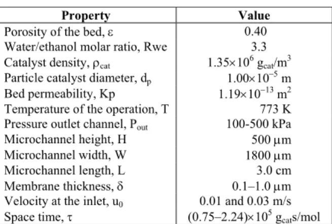
Table 3: Flow and mass transfer parameters.
Property Value
Porosity of the bed, ε 0.40 Water/ethanol molar ratio, Rwe 3.3 Catalyst density, ρcat 1.35×10⁶ gcat/m3
Particle catalyst diameter, dp 1.00×10⁻⁵ m
Bed permeability, Kp 1.19×10⁻¹³
m2 Temperature of the operation, T 773 K
Pressure outlet channel, Pout 100-500 kPa
Microchannel height, H 500 μm Microchannel width, W 1800 μm Microchannel length, L 3.0 cm Membrane thickness, δ 0.1–1.0 μm Velocity at the inlet, u0 0.01 and 0.03 m/s
Space time, τ (0.75–2.24)×105 g cats/mol
The local average ethanol conversion, denoted e
χ , and the product yields, denoted Y , were i calculated according to Eqs. (18) and (20), respectively.
H 0
e e
1
(x) (x, y)dy H
χ =
∫
χ (18)in which
e
o o o
u P Xe (x, y) 1
u P Xe
⎛ ⎞⎛ ⎞⎛ ⎞
χ = − ⎜ ⎟⎜ ⎟⎜ ⎟
⎝ ⎠⎝ ⎠⎝ ⎠ (19)
i i
i
eo o o o
F X uP Y (x)
F Xe u P
= = (20)
where
H 0
i i
1
X (x) X (x, y)dy H
=
∫
(21)Feo represents the molar flow rate of the ethanol at
the inlet of the microchannel, Fi the average molar
flow rate of the product i at a generic distance from the entrance of the microchannel,and Xi is the local average mole fraction of species i.
362 M. de-Souza, G. M. Zanin and F. F. Moraes
Brazilian Journal of Chemical Engineering
predictive ability of the numerical model for the product yields can be observed.
A discrepancy between the experimental conversion of the ethanol and the conversion predicted by the model is observed in this figure, mainly at the beginning of the reaction. The experi-mental results obtained by Comas et al. (2004b) show that ethanol is completely converted at very short contact times while the model predicts a different profile. The discrepancy between the experimental results and the values predicted by the model is due to the low kinetic coefficient proposed by Sun et al. (2005) and used in this paper for Reaction 2. According to Mas et al. (2006) ethanol is first completely converted into ethylene and acetaldehyde, which are subsequently converted into carbon oxides, methane and hydrogen. These reactions were not considered in the reaction pathway proposed in this paper, although Comas et al. (2004b) showed that, for a Ni/Al2O3 catalyst, both
ethylene and acetaldehyde are intermediate products formed from ethanol dehydration and dehydrogenation, respectively.
Nevertheless, the results validate our formulation of the numerical model, as well as the solution of the partial differential equations using the COMSOL Multiphysics® package and the assumptions made in terms of the reaction pathway and kinetic expressions.
Figure 3: Experimental vs. model predicted yield
and ethanol conversion values at Rwe = 3.3, T = 773 K, P = 100 kPa, u0 = 0.03 m/s, τ = 2.24×10⁵ gcats/molEtOH
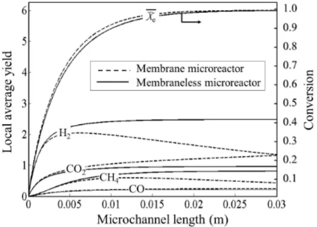
The main advantage of the membrane microreactor is the improvement in conversion of the Reactions 3, 4 and 5 as a result of selective hydrogen removal. Due to the reaction rates given in Eqs. (1) through (4), the equilibrium is reached for a space
time of approximately 7.5×10⁴ gcats/mol, which is
equivalent to a length of the microchannel of 0.01 m. Thus, as shown in Figure 4, the effective micro-channel length for a membraneless microreactor is about 0.01 m, after which the hydrogen yield reaches a maximum value. In the membrane microreactor, with a 0.2 μm membrane thickness, the effective microchannel length can be over 0.03 m since Reactions 3, 4 and 5 are shifted by hydrogen removal. Another advantage of the membrane microreactor is the production of pure hydrogen outside the membrane to supply a PEM fuel cell. In Figure 4 a lower hydrogen mole fraction throughout the membrane microreactor than in the membraneless microreactor is observed, indicating hydrogen removal from the reaction zone and thus the shift of Reactions 3, 4, and 5 towards those products. Thus, the removal of hydrogen from the reaction medium by its flow through the membrane dislocates the reaction towards the formation of greater yields of hydrogen. The figure also shows an increase in CO2
mole fraction and a lower CH4 mole fraction, which
correspond to the higher amounts of hydrogen produced.
Figure 4: Comparison of local average yield and
local average ethanol conversion between the membrane microreactor and the membraneless microreactor at Rwe = 3.3, T = 773 K, Po = 100 kPa,
u0 = 0.03 m/s, τ = 2.24×10 5
gcats/molEtOH and δ= 0.2 μm.
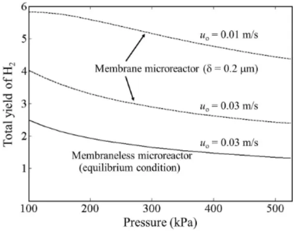
Hydrogen yields near 6 are obtained only for the reactor fitted with a 0.2 μm palladium membrane, an inlet pressure < 300 kPa and an inlet velocity of 0.01 m/s. For the conventional reactor hydrogen yields are lower than 2.50 (see Fig. 5). When a 0.2 μm membrane thickness is used, the total hydrogen yield (Yh,total) increased from 2.50 to 4.05 if
Parametric Study of Hydrogen Production from Ethanol Steam Reforming in a Membrane Microreactor 363 entrance, as shown in the Figure 5; alternatively, if it
operated at P = 300 kPa and uo = 0.01 m/s the total
hydrogen yield increased to 5.13. This represents an increase of 105% over the membraneless microreactor in the equilibrium condition. The total hydrogen yield is calculated from Eq. (22):
h,total h,total
eo F Y
F
= (22)
where Fh,total is the total molar flow of hydrogen in
mol/s and it can be estimated by
(
)
( )
0 0
H L
h,total hx L hy 0
F =W⎡⎢ N = dy+ N = dx⎤⎥
⎣
∫
∫
⎦ (23)The first integral in Eq. (23) refers to the molar flow of hydrogen that leaves the reformer in the outlet microchannel boundary, while the second integral refers to the molar flow of hydrogen across the membrane.
Figure 5: Total hydrogen yield (Yh,total) in function
of the inlet pressure at Rwe = 3.3, T = 773 K, uo = 0.01 or 0.03 m/s and δ = 0.2 μm for the membrane
microreactor.
The model used does not quantify the mass transfer rate gas-catalyst and, for the conventional reactor, the final composition is not affected by the inlet velocity. However, the intermediary composition along the microchannel is affected by the inlet velocity. On the contrary, as shown in Figure 5, for the membrane reactor, the outlet composition depends on the inlet velocity.
Although higher pressures improve the hydrogen permeability through the membrane, increased pressure has a negative influence on hydrogen formation. Figure 5 shows that higher pressure reduces
the hydrogen yield for both the membraneless and membrane microreactors. This is caused by the expansion of the gas volume as the reactions proceed. Higher pressures worsen the equilibrium conditions of Reactions 4 and 5, increasing the methane yield in detriment to the hydrogen yield. Apart from this, high pressure leads to a higher concentration of reactants. This result is in agreement with other authors (Comas et al., 2004a; Song et al., 2005).
Figure 5 also shows that the reactant velocity at the microchannel entrance is important for the resulting total hydrogen yield of the membrane microreactor. A lower velocity leads to a higher yield, because the space time is higher too.
In Figure 6, the effect of the membrane thickness (δ) on the total hydrogen yield at different space times (τ = catalyst mass per molar flow rate of ethanol feed) is shown. It can be seen that by decreasing membrane thickness, mainly for values lower than 0.5 μm, the total hydrogen yield increases greatly for all space times analyzed. This means that membrane thickness has a significant effect on the performance of the microreactor. Thus, for a space time of 2.24×10⁵ gcats/mol and a 0.2 μm membrane
thickness, the total hydrogen yield reaches values as high as 5.13 mol of hydrogen per mol of ethanol feed, compared to a maximum yield of 6 considering complete ethanol steam reforming (Reaction 1).
Figure 6: Influence of membrane thickness (δ) at
different space times (τ) on the total hydrogen yield (Yh,total). Rwe = 3.3, Po = 300 kPa and T = 773 K.
364 M. de-Souza, G. M. Zanin and F. F. Moraes
Brazilian Journal of Chemical Engineering
palladium film (Karnik et al., 2003). In our model we consider that the copper, aluminum and SOG layers provide strength to the membrane, but offer no resistance to flow. Thus, the membrane was modeled only by the film of palladium. Besides the work of Karnik et al. (2003), other works such as Shi and Szpunar (2007) and Shi et al. (2009), indicate the possibility of fabricating Pd-based membranes of nanometric thicknesses that can withstand pressure differences over 300 kPa and temperatures up to 773K. Because our interest focuses on a parametric theoretical study we were mostly concerned with the order of magnitude of the permeability parameter.
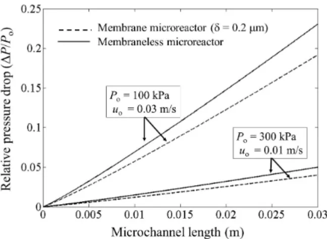
The pressure drop along the microchannel at two different pressures and a fixed space time of 2.24×10⁵ gcats/mol is presented in Figure 7. It can be
observed for both pressures (100 and 300 kPa) that the relative pressure drop decreases when the membrane microreactor is used instead of the membraneless microreactor. This is due to the fact that hydrogen removal contributes to the reduction of the axial velocity along the microchannel.
Figure 7: Pressure drop at a space time of
2.24×10⁵ gcats/mol., inlet pressure of 100 and 300 kPa,
and 0.2 μm membrane thickness for the membrane microreactor.
Figure 8 shows the hydrogen mole fraction profile (Xh) along the microchannel (along the x
axis, membrane at y = 0). It can be seen that Xh first
increases and then decreases, indicating that hydrogen is produced and is subsequently partially removed through the membrane located at the microchannel inferior boundary.
The outlet flow rates of all species resulting from the membrane microreactor model at δ = 0.2 μm, uo = 0.01 m/s and Po = 300 kPa, are shown in Table
4, in which the second and third column correspond to the cumulative values throughout the flow
cross-section and the fourth column corresponds to the cumulative value along the reactor length. It can be noted that 83.9% from the produced hydrogen (5.29×10⁻⁷ mol/s) permeates through the selective membrane, ensuring a source of high-purity hydrogen that can be directly utilized in a PEM fuel cell. The remaining 16.1% of the hydrogen of the reformate can be used for heat generation, which is required for the endothermic steam reforming.
Figure 8: Mole fraction profile of hydrogen along
the microchannel in the membrane microreactor at T = 773 K; uo = 0.01 m/s (τ = 2.24×10⁵ gcats/molEtOH)
P0 = 3 atm, Rwe = 3.3 and δ = 0.2 μm
Table 4: Predicted effluent cumulative flow rates along the reactor length or width resulting from the numerical model for the membrane
micro-reactor with a 0.2 μm membrane thickness, at
Po = 300 kPa and uo = 0.01 m/s
Total flow rates (mol/s)
Value at x = 0, 0 ≤ y ≤ H
Value at x = L, 0 ≤ y ≤ H
Value at y = 0, 0 ≤ x ≤ L
Fe 1.03×10⁻⁷ ≅ 0 0
Fw 3.40×10⁻⁷ 8.20×10⁻⁸ 0
Fme 0 1.83×10⁻⁸ 0
Fm 0 1.53×10⁻⁸ 0
Fd 0 1.73×10⁻⁷ 0
Fh 1.33×10⁻⁹ 8.53×10⁻⁸ 4.44×10⁻⁷
Parametric Study of Hydrogen Production from Ethanol Steam Reforming in a Membrane Microreactor 365 CONCLUSION
In this work, ethanol steam reforming was studied by a numerical comparison of a membrane microreactor with a membraneless microreactor. Model results showed that thin membranes (< 0.5 μm) increase the total hydrogen yield by up to 105% at temperature of 773 K. In addition, more than 80% of the total hydrogen produced permeated across the membrane. Thus, membrane micro-reactors can be successfully applied to produce high-purity hydrogen for fuel cell systems, which can generate power for modern multifunctional portable devices.
The main contribution and novelty of this work is the conception of a membrane microreactor, in which both ethanol steam reforming and separation of hydrogen occur in one single microdevice. Potential advantages of this microreactor are its higher hydrogen production and elimination of the hydrogen purification stage for a PEM fuel cell, which requires CO concentrations below 20 ppm. Additionally, catalytic oxidation of the exhaust gases generate the thermal energy required for the endothermic steam reforming.
NOMENCLATURE
Def,i effective
concentration-driven diffusion coefficient of the specie i
m2 s−1
Di diffusion coefficient of the
specie i in the
multicomponent mixture
m2 s−1
Dik binary diffusivity for the
pair i−k in the
multicomponent system
m2 s−1
dp catalyst particles diameter m
Fh,total total molar flow rate of
hydrogen
mol s−1 Fi molar flow rate of species i
at a generic distance from the entrance of the microchannel
mol s−1
Fio molar flow rate of the
species i at the inlet of the microchannel
mol s−1
H channel height m
K Boltzmann constant J K−1 kj reaction rate constant of the
jth reaction
Kj equilibrium constant of the
jth reaction
kp permeability of the
membrane
mol m−2s−1Pa−1 Kp bed permeability mol m−2s−1Pa−1
L channel length m
Mi molecular weight of an
individual component
kg mol−1 Ni flux of the specie i in the
direction normal to the boundary
mol m−2s−1
P pressure Pa
P0 pressure at the inlet of the
microchannel
Pa
Pe Peclet number (-)
Ph,outside partial pressure of the
hydrogen outside of the membrane
Pa
Pout pressure at the outlet of the
microchannel
Pa
Rg universal gas constant 8.314 J mol−1K−1
rj
reaction rate of the jth reaction
mol s−1gcat−1
T temperature K
u component of the velocity vector in the x direction
m s−1
u fluid flow velocity vector m s−1 uo fluid flow velocity at the
inlet of the microchannel
m s−1 v component of the velocity
vector in the y direction
m s−1 vp velocity of the fluid as it
diffuses through the membrane
m s−1
W channel width m
wcat catalyst mass g
x, y cartesian coordinates m Xi mole fraction of component i (-)
i
X Xi(x) = local average mole fraction of species i
(-)
Xi 0 mole fraction of component
i at the inlet of the microchannel
(-)
Yh,total total hydrogen yield (-)
i
Y Yi(x) = Fi/Fe0 = local
average products yields
(-)
Greeks Letters
δ membrane thickness m
ε porosity of the bed (-)
εi k maximum attractive energy
between molecule i and molecule k
J
366 M. de-Souza, G. M. Zanin and F. F. Moraes
Brazilian Journal of Chemical Engineering
μi viscosity of an individual
component
kg m−1s−1
νi j stoichiometric coefficient of
component i in jth reaction
ρcat catalyst mass per unit of
volume,
kg m−3
σik collision diameter Å
τ space time gcat s mol−1
τik dimensionless temperature (-)
Φi k Chapman–Enskog parameter (-)
Ωik collision integral (-)
e
χ χe(x) = local average ethanol conversion
(-)
Subscripts
d CO2 (carbon dioxide) e EtOH = C2H5OH (ethanol)
h H2 (hydrogen gas)
i, k species in multicomponent systems
j reaction
m CO (carbon monoxide) me CH4 (methane)
w 2O (water)
REFERENCES
Aicher, T., Full, J., Schaadt, A., A portable fuel processor for hydrogen production from ethanol in a 250 Wel fuel cell system. Int. J. Hydrogen
Energy, 37, pp. 8006-15 (2009).
Alfadhel, A. A., Kothare, M. V., Microfluidic modeling and simulation of flow in membrane microreactors. Chem. Eng. Sci., 60, pp. 2911-26 (2005).
Aravamudhan, S., Rahman, A. R. A., Bhansali, S., Porous silicon based orientation independent self-priming micro direct ethanol fuel cell. Sens. Actuators, A, 123-4, pp. 497-504 (2005).
Assaf, E. M., Jesus, C. D. F., Assaf, J. M. Mathematical modeling of methane steam reforming in a membrane reactor: an isothermic model. Braz. J. Chem. Eng. 15, no. 2, June (1998).
Bird, R. B., Stewart, W. E., Lightfoot, E. N., Fenô-menos de Transporte. 2nd Ed., LTC, Rio de Janeiro (2004). (In Portuguese).
Comas, J., Laborde, M., Amadeo, N., Thermodynamic analysis of hydrogen production from ethanol using CaO as a CO2 sorbent. J. Power Sources,
138, pp. 61-67 (2004a).
Comas, J., Mariño, F., Laborde, M., Amadeo, N., Bio-ethanol steam reforming on Ni/Al2O3
catalyst. Chem. Eng. J., 98, pp. 61-8 (2004b). Delsman, E. R., Microstructured Reactors for a
Portable Hydrogen Production Unit. Ph.D Thesis, Technische Universiteit Eindhoven, Eindhoven, Netherlands (2005).
Deshmukh, S. R., Vlachos, D. G., Effect of flow configuration on the operation of coupled combustor/reformer microdevices for hydrogen production. Chem. Eng. Sci., 60, pp. 5718-28 (2005).
Dixon, A. G., Correlations for wall and particle shape effects on fixed bed bulk voidage. Can. J. Chem. Eng., 66, 705 (1988).
Falco, M., Gallucci, F., Ethanol steam reforming heated up by molten salt CSP: Reactor assessment. Int. J. Hydrogen Energy, 35, pp. 3463-71 (2010).
Fatsikostas, A. N., Verykios, X. E., Reaction network of steam reforming of ethanol over Ni-based catalysts. J. Catal., 225, pp. 439-52 (2004). Haryanto, A., Fernando, S., Murali, N., Adhikari, S.,
Current status of hydrogen production techniques by steam reforming of ethanol: A review. Energ. Fuel, 19, pp. 2098-106 (2005).
Hotza, D., Costa, J. C. D., Fuel cells development and hydrogen production from renewable resources in Brazil. Int. J. Hydrogen Energy, 33, pp. 4915-35 (2008).
Hu, J., Wang, Y., Vanderwiel, D., Chin, C., Palo, D., Rozmiarek, R., Dagle, R., Cao, J., Holladay, J., Baker, E., Fuel processing for portable power applications. Chem. Eng. J., 93, pp. 55-60 (2003). Iulianelli, A., Longo, T., Liguori, S., Seelam, P. K.,
Keiski, R. L., Basile, A., Oxidative steam reforming of ethanol over Ru-Al2O3 catalyst in a
dense Pd-Ag membrane reactor to produce hydrogen for PEM fuel cells. Int. J. Hydrogen Energy, 34, pp. 8558-65 (2009).
Karnik, S. V., Hatalis, M. K., Kothare, M. V., Towards a palladium micro-membrane for the water gas shift reaction: Microfabrication approach and hydrogen purification results. J. Microelectromechanical Sys., 12, pp. 93-100 (2003).
Kawamura, Y., Ogura, N., Yamamoto, T., Igarashi, A., A miniaturized methanol reformer with Si-based microreactor for a small PEMFC. Chem. Eng. Sci., 61, pp. 1092-101 (2006).
Parametric Study of Hydrogen Production from Ethanol Steam Reforming in a Membrane Microreactor 367 Klouz, V., Fierro, V., Denton, P., Katz, H., Lisse, J.
P., Bouvot-Mauduit, S., Mirodados, C., Ethanol reforming for hydrogen production in a hybrid electric vehicle: Process optimization. J. Power Sources, 105, pp. 26-34 (2002).
Lee, D. K., Baek, I. H., Yoon, W. L., A simulation study for the hybrid reaction of methane steam reforming and in situ CO2 removal in a moving
bed reactor of a catalyst admixed with a CaO-based CO2 acceptor for H2 production. Int. J.
Hydrogen Energy, 31, pp. 649-57 (2006).
Löwe, H., Ehrfeld, W., State-of-art in microreaction technology: Concepts, manufacturing and applications. Electrochim. Acta, 44, pp. 3679-89 (1999).
Mariño, F., Boveri, M., Baronetti, G., Laborde, M., Hydrogen production from steam reforming bioethanol using Cu/Ni/K/γ−Al2O3 catalysts -
Effect of Ni. Int. J. Hydrogen Energy, 26, pp. 665-8 (2001).
Mas, V., Kipreos, R., Amadeo, N., Laborde, M., Thermodynamic analysis of ethanol/water system with the stoichiometric method. Int. J. Hydrogen Energy, 31, pp. 21-8 (2006).
Neufeld, P. D., Jansen, A. R., Aziz, R. A., Empirical equations to calculate 16 of the transport collision integrals Ω(l,s)* for the Lennard-Jones (12–6) potential. J. Chem. Phys. 57, pp. 1100-1102 (1972).
Palo, D. R., Holladay, J. D., Rozmiarek, R. T., Guzman-Leong, C. E., Wang, Y., Hu, J., Chin, Y., Dagle, R. A., Baker, E. G., Development of a soldier-portable fuel cell power system Part I: A bread-board methanol fuel processor. J. Power Sources, 108, pp. 28-34 (2002).
Pattekar, A. V., Kothare, M. V., Modeling, design and control of silicon based microchemical systems. Ann. Meet. AIChE, Indianapolis (2002). Pattekar, A. V., Kothare, M. V., A microreactor
for hydrogen production in micro fuel cell applications. J. Microelectromech. S., 13, pp. 7-18 (2004).
Pattekar, A. V., Kothare, M. V., Karnik, S. V., Hatalis, M. K., A microreactor for in-situ hydrogen production by catalytic methanol reforming. 5th IMRET, Strasbourg (2001).
Perry, R. H., Green, D. W., Maloney, J. O., Perry’s Chemical Engineers’ Handbook. 7th Ed., McGraw Hill, New York (1997).
Shi, Z., Szpunar, J. A., Synthesis of an ultra-thin palladium membrane for hydrogen extraction. Rev. Adv. Mater. Sci., 15, pp. 1-9 (2007).
Shi, Z., Szpunar, J. A., Wu, S., Design and synthesis of thin palladium membranes on porous metal substrate for hydrogen extraction. J. Phys. Conf. Ser., 165 012062 (2009).
Song, H., Zhang, L., Watson, R. B., Braden, D., Ozkan, U. S., Investigation of bio-ethanol steam reforming over cobalt-based catalysts. Catal. Today, 145, pp. 502-14 (2007).
Sordi, A., Silva, E. P., Milanez, L. F., Lobkov, D. D., Souza, S. N. M., Hydrogen from biomass gas steam reforming for low temperature fuel cell: Energy and exergy analysis. Braz. J. Chem. Eng., 26, pp. 159-169 (2009).
Sun, J., Qiu, X. P., Wu, F., Zhu, W. T., H2 from
steam reforming of ethanol at low temperature over Ni/Y2O3, Ni/La2O3, Ni/Al2O3 catalysts for
fuel-cell application. Int. J. Hydrogen Energy, 30, pp. 437-45 (2005).
Terazaki, T., Nomura, M., Takeyama, K., Nakamura, O., Yamamoto, T., Development of multi-layered microreactor with methanol reformer for small PEMFC. J. Power Sources, 145, pp. 691-696 (2005).
Therdthianwong, A., Sakulkoakiet, T., Therdthianwong, S., Hydrogen production by catalytic ethanol steam reforming. Science Asia, 27, pp. 193-8 (2001).
Trimm, D. L., Design of Industrial Catalysts. Elsevier Scientific Publishing Company, New York (1980). Vaidya, P. D., Rodrigues, A. E., Insight into steam
reforming of ethanol to produce hydrogen for fuel cells. Chem. Eng. J., 117, pp. 39-49 (2006). Wang, Y. N., Rodrigues, A. E., Hydrogen production
from steam methane reforming coupled with in situ CO2 capture: Conceptual parametric study.
Fuel, 84, pp. 1778-89 (2005).
Winter, C. J., Hydrogen energy – abundant, efficient, clean: A debate over the energy-system-of-change. Int. J. Hydrogen Energy, 34, S1-S52 (2009).
Wörz, O., Jäckel, K. P., Richter, Th., Wolf, A., Microreactors, a new efficient tool for optimum reactor design. Chem. Eng. Sci., 56, pp. 1029-33 (2001).
Xu, J. G., Froment, G. F., Methane steam reforming, methanation and water-gas shift: I. Intrinsic kinetics. AIChE J., 35, 88-96 (1989)