77
Abstract
The economics of a mining operation is directly inluenced by blasting outcomes, where blasting aims to comminute the rock mass in order to attain smaller grain sizes to be loaded and hauled at a minimum cost for its irst processing stage. In order to promote adequate rock breakage, the stemming structure needs to provide proper coninement for the borehole charged with explosives, relecting the energy released during the detonation in form of shock waves and gases to act throughout the in situ
rock mass, enlarging its failures and fractures, and also creating new ones. To build up a stemming column, literature recommends the usage of dry granular materials instead of elements with plastic behavior. However, a study was performed using Gyp-sum plaster as stemming; a kind of material that exhibits solid-like behavior when it is dry. Following this theory, this test veriied improvements regarding coninement ef-fectiveness and energy propagation throughout the rock mass when a non-Newtonian mixture (NNM) was applied as stemming; a material that shows a solid-like behavior when is under shear stress. When the stemming arrangement was composed of NNM, it was able to reduce energy and gas losses to the atmosphere, because of the liquid’s property of illing voids into the borehole. The NNM yielded high results due to its better coninement effectiveness, a reduction of air overpressure, and an increase of the strain propagation and ground vibration throughout the rock.
Keywords: effective coninement, non-Newtonian mixture, stemming, strain propagation.
Luís Felipe Gomes Marinho
Graduando
Universidade do Estado de Minas Gerais - UEMG João Monlevade - Minas Gerais - Brasil
Hiago Gonçalves Vasconcelos
Bacharelando em Engenharia de Minas Universidade do Estado de Minas Gerais - UEMG Faculdade de Engenharia
Assessor de Projetos – Metal Minas Consultoria Jr. Belo Horizonte - Minas Gerais - Brasil [email protected]
Braden Lusk
Researcher, Professor of Mining Engineering and Director of Graduate Studies
University of Kentucky
College of Engineering - Mining Engineering Lexington, Kentucky - United States [email protected]
Giuliano Antonio Pizzatto Rapucci
Analista Operacional Sênior do VALE S.A, Mestre Universidade Federal do Rio Grande do Sul - UFRS Porto Alegre - Rio Grande do Sul – Brasil [email protected]
Achieving effective
confinement through
utilization of non-Newtonian
fluid mixture as stemming structure
Mining
Mineração
http://dx.doi.org/10.1590/0370-44672016700077
1. Introduction
The blasting operation is consid-ered one of the most important activities in Mining due to its capability to make the fragmentation process considerably more economical. During past decades, stemming, a simple and effective blasting tool, has not received the attention and investments it deserves. Stemming, as highlighted by Rai, Ranjan & Choud-hary (2008) "is an important controllable parameter that greatly inluences [...] the release of energy from the explosion." Since stemming has a great role in blast-ing operations, almost on the same level of the explosives, it should be studied and developed in equal proportion.
Over the years, mining engineers and blasting professionals have used drill cuttings or coarse materials, such as gravel or crushed stone, for stemming columns. In fact, since these materials are readily available at the mine site, and, in general, do not add signiicant cost to the blasting process. However, if the fragmentation process is analyzed in overall, the ap-plication of these materials on stemming, directly inluences the coninement ef-iciency of blastholes and, therefore, the quality of rock blasting.
ISEE Blasters' Handbook (2011) cites that stemming is a column composed of inert material and is used to promote
energy coninement within the hole on top of the explosive charge. When stem-ming provides adequate confinement, the resulting beneits include retention of explosives gases within the borehole, gas pressure, and eficient rock breakage due to maximum energy absorption (RAI et al., 2008).
application of explosives and time saving with reduction of the secondary blasting; increasing the operational eficiency due to fragment size adequacy for loaders and trucks speciications; reduction of obstruc-tions on the primary crusher causing bet-ter performance of the processing plant.
The present article shows a study of a new stemming application that improved important parameters considered crucial for promoting blasting optimization. Us-ing a mixture made with cornstarch and water as a stemming component, this test concluded that the non-Newtonian
Mixture (NNM) promoted better energy coninement within the hole. The results include improvements on parameters such as strain distribution along the rock mass, losses of energy by air overpressure, stem-ming ejection and audible airblast released during the detonation.
2. Methodology
Five rounds of small-scale tests were conducted at the University of Kentucky Explosives Research Team’s (UKERT) laboratory located in an underground limestone quarry in Georgetown, Ken-tucky. The purpose of this testing was to verify the coninement effectiveness
provided by a non-Newtonian mixture used as a stemming component. In addi-tion, the relationship between the material employed in the stemming column was compared to the rock’s absorption of en-ergy provided by the detonation.
A non-Newtonian luid is a luid
that does not conform to Newton’s law of viscosity, in that viscosity for these luids is a function of shear rate (MASSOUD, 2005). The luid behaves as a solid when a shear stress is applied to it. Therefore, its viscosity increases as much as the shear stress applied increases.
2.1 Stemming configurations
Between May 22, 2015 and June 29, 2015, a battery of 23 tests wereperformed. The tests were divided into five rounds of six different stemming
conigurations, which are schematically represented in Figure 1.
Figure 1
Boreholes layout.
C1: All NNM (coupling and stem-ming);
C2: The NNM coupling and moist sand stemming. A ifth round with three shots in this coniguration was exclusively carried out on June 29, 2015, in order to compare its results with the others previ-ously obtained in Rounds #1 to #4;
C3: All sand (coupling and stemming);
C4: Air coupling and sand stem-ming (a rubber plug was placed above the charge and the remainder of the hole was stemmed using dry sand);
C5: Sand coupling and the NNM (non-Newtonian mixture) stemming (a half-inch (12.7mm) thick rubber plug was used to separate the dry sand from the luid);
C6: No material used for coupling or stemming (open borehole);
The testing of different coupling/ stemming combinations allowed com-parison of parameters, such as the energy propagation throughout the rock and the borehole coninement. For example, an air coupled charge will transfer less
energy into the surrounding rock mass when compared to a fully coupled charge using materials such as sand, gravel or water. Given this knowledge, it can be assumed that the overall energy parti-tions will be skewed based on the type of coupling material.
The stemming size, as it is known according to the general rule of thumb, should be no greater than 1/8 of the hole diameter, and the stemming height should be at least 24 times that of the hole diameter.
2.2 Borehole
One single hole was drilled in the loor of the test area at a distance of 10.4 feet (3.17m) from a central point. This point would later serve as the geophone and seismograph mounting location during Round #1 of testing. From Round #2 on, the
equipment was moved to half of the central point distance toward the borehole (5.2 feet or 1.58m). The hole was drilled in laboratory scale using a hammer drill with a 7/8 inch (0.022m) bit to a depth of approximately 30 inches (0.762m). Compressed air
was used to remove any drill cut-tings, and then again after the test to remove any ine material created by the blast. After each shot, the hole was re-drilled in order to guarantee a uniform depth of approximately 30 inches (0.762m).
2.3 Charges
Round #1 was conducted on May 22, 2015, using 18 inches (0.46m) of 25 grain per foot detonating cord (yielding 0.0054 lbs. (0.0024kg) of explosives)
ex-clusively to calibrate the equipment, set up the explosives charge, and guarantee elimination of movement and breakage from the rock mass.
79
vibration. Airblast, stemming ejection and heat are all uses of the explosive energy or results of the blast.
For the other four rounds, the test procedure was modiied to double
the explosive weight used in Round #1 (50 grain per foot detonating cord), with the exception of using 16 inches (0.41m) of detonating cord folded into four inch (0.10m) sections to
give more stemming depth, increase charge weight, and increase the stem-ming height. This time, the detonating charge yielded 0.0095 lbs. (0.0043kg) of explosives.
2.4 Non-Newtonian fluid mixture preparation
T he non-New tonian mix ture(NNM) ingredient was selected to be tested due to three main reasons: irst, because the mixture created using this material has ad-equate physical properties that are able to hold high levels of shear stress. Second, the
material used to make this mixture is very inexpensive and easy to ind. Third, this ingredient is largely employed in mining for the lotation process of some ores, such as iron, and therefore is readily available.
The NNM was prepared until it
reached a true solid-like behavior, when after applying a shear stress to the mix-ture, it behaves like a solid. The NNM needs to be mixed before hole charging in order to have a uniform concentration and viscosity.
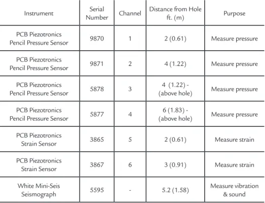
2.5 Instrumentation
To accurately capture as many variables as possible, a wide array of sensors were deployed for data
collec-tion during the blasting events.
The instrumentation used to measure the various blast pressures,
velocities, and vibrations are listed in the Table 1.
Instrument Serial
Number Channel
Distance from Hole
ft. (m) Purpose
PCB Piezotronics
Pencil Pressure Sensor 9870 1 2 (0.61) Measure pressure
PCB Piezotronics
Pencil Pressure Sensor 9871 2 4 (1.22) Measure pressure
PCB Piezotronics
Pencil Pressure Sensor 5878 3
4 (1.22)
-(above hole) Measure pressure
PCB Piezotronics
Pencil Pressure Sensor 5877 4
6 (1.83) -
(above hole) Measure pressure
PCB Piezotronics
Strain Sensor 3865 5 2 (0.61) Measure strain
PCB Piezotronics
Strain Sensor 3867 6 3 (0.91) Measure strain
White Mini-Seis
Seismograph 5595 - 5.2 (1.58)
Measure vibration & sound Table 1
Instrumentation.
The free-field pressure sensors were mounted co-linearly on a frame
at distances of 4 and 6 feet (1.22 and 1.83m) high from the borehole collar as
shown in the Figure 2 below.
The pencil pressure sensors were set up on the hole at a 45-degree angle as shown in Figure 3.
Figure 3
Typical Pencil Pressure Sensor Array.
The frame was positioned at a 45 degree angle to the borehole based on the assumption that the air overpressure shell would expand hemispherically, as is commonly witnessed in explosive charges detonated at ground level, and then be
captured by the sensors at this inclination. Strain sensors were placed transverse to the orientation of the force of the ex-plosion as it propagates through the rock in order to measure the expansion of the rock due to blast pressure. The surface of
the rock loor was cleaned using acetone at the locations for the strain sensors, and these were attached to the rock using a speciic super glue brand recommended by the sensor manufacturer, as shown in the Figure 4 below.
Figure 4
Typical Strain Sensor Set Up.
The seismograph was used for vibra-tion measurements. The hole geophone
array was connected to the rock via a steel plate, as shown in Figure 5.
Figure 5
Typical Geophone and Seismograph Array.
T he seismog raph was posi-tioned at the center of the test area, 10.4 feet (3.17m) from the borehole for
Round #1, when the instrumentation was being calibrated. From Round #2 on, this equipment was moved 5.2 feet (1.58m)
closer to the borehole.
A high-speed camera, as shown in Figure 6, was used to record each blast.
Figure 6
81
3. Procedure
i) The instruments of measurement (high-speed camera, sensors, seismograph, laptop…) and the illumination were set as described in the Instrumentation section.
The hole was charged using detonat-ing cord and blastdetonat-ing caps. The explosive was placed at the bottom of the hole.
ii) The hole was charged by the blaster that used explosives, speciied in the Charges section.
iii) After the hole was charged, the coupling and stemming material were placed into the hole, following the general
rule of thumb speciied in the Stemming Assays section. In each shot a different coupling and stemming combination was tested, which means that for each round, ive different shots were carried out.
iv) Following the standard detona-tion procedure, the blaster shot the hole, while an auxiliary worker triggered the high-speed camera through wireless re-mote control. After the detonation, the blaster checked the test area and inally checked if the equipment recorded the data and the images. Meanwhile, the hole was
re-drilled and cleaned out after each shot to prepare for the next test.
The tests were performed again fol-lowing the abovementioned steps until six stemming combinations (totaling a round of test) were tested. A ifth round of three shots [of the NNM coupling and sand stemming] was carried out on June 29th, 2015, in order to compare its results with the others previously obtained in Rounds #1 to #4. At the end of each round, the equipment was stored, except for rounds 3 and 4, which were done on the same day.
4. Results
From Round #1 conducted on May 22, 2015, ive shots were carried out. For shots 1, 2, 3 and 4, the stemming columns were blown out from the hole, and in shot 5, no stemming and coupling
were applied. The subsequent rounds were performed using double charge explosives (16 inches (0.41m) of 50 grain per foot detonating cord) folded into four inch sections to increase stemming length
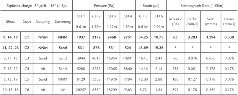
and charge weight. Table 2 contains the average results calculated from 18 shots performed in Rounds #2 to #5. The re-sults are classiied according to the type of coupling and stemming material tested.
Explosive charge 50 gr/ft. - 16" (4.3g) Pressure (Pa) Strain (µε) Seismograph Data (1.58m)
Shots Code Coupling Stemming
CH 1 CH 2 CH 3 CH 4 CH 5 CH 6
Acoustic (Pa)
Radial (mm/s)
Vert. (mm/s)
Transv. (mm/s)
0.61m 1.22m 1.22m 1.83m 0.61m 0.91m
9, 14, 17 C1 NNM NNM 1937 2172 2468 2751 54.25 10.75 63 0.203 1.194 0.330 21, 22, 23 C2 NNM Sand 531 876 531 524 43.69 19.36 * * * *
8, 11, 16 C3 Sand Sand 3944 4613 15954 10901 16.13 2.41 86 0.076 0.076 0.076
7, 13, 20 C4 Air Sand 5288 3282 15065 8860 14.16 2.14 233 0.051 0.178 0.178
6, 12, 19 C5 Sand NNM 6129 3358 11976 7784 12.88 2.88 186 0.127 0.178 0.076
10, 15, 18 C6 Air Air 20257 8350 18209 9363 8.72 1.54 399 0.178 0.330 0.178
Table 2. Average assays
Round #2 was conducted on May 27, 2015. Through the image analysis taken by the high-speed camera, it was observed that the stemming structures were blown out from the borehole in all shots, and shots 8 and 9 (conigurations C3 and C1, respectively) had quieter au-dible airblasts.
When the explosions have low air overpressures, it means that the stemming structure held the shockwave and the gas-es within the borehole, allowing for more energy to be transmitted into the borehole wall and thus, the surrounding rock.
Also, when air overpressure was compared between those shots
(cap-tured by channels 1, 2, 3 and 4), it can be inferred that the hole with all NNM (arrangement C1) had the lowest values, while the shot with sand stemming and air coupled (arrangement C4) had the highest air overpressure values (excluding the non-stemmed hole). Moreover, when the strain distributed to the rock was analyzed, the NNM, applied in arrangements C1 and C2, was the material with the highest values for channels 5 and 6, which means that the borehole was better conined with this mixture, distributing more energy and vibration around the rock mass rather than letting it escape to the atmosphere.
Rounds #3 and #4 were conducted
on June 1, 2015. As before in Round #1, through the image analysis taken by high-speed camera, it was observed that the stemming structures were blown out from the borehole in all shots. In shots 14 and 17 (arrangement C1), lower noise was observed from the detonation than from shots 12 and 19 (arrange-ment C5). In the laboratory analysis it was observed through the seismograph analysis that shots 14 and 17 had the lowest air overpressures.
crack-ing at the borehole collar occurred. Collar damage is indicative of stemming failure; however this damage was expected, due to the existence of a bedding plane at the borehole’s collar prior to several blasts.
Round #5 was conducted on June 29, 2015. Through the images taken by the high-speed camera, it was observed, however, that the stemming structures had minimal movement. Additionally, a preliminary analysis of the audible airblast concluded that the lowest noise was heard from all the rounds. This low audible air-blast made the air-blaster think, instinctively, that a misire had happened. However, he concluded that, in fact that explosive had detonated and the quieter noise heard was because the stemming structure held the
blasthole very well.
Analyzing channels 1 to 4, it can be concluded that the C1 and C2 ar-rangements (NNM/NNM and NNM/ sand for coupling/stemming) had the two lowest air blasting and overpressure values compared to those obtained from the other conigurations.
Regarding strain measurements (taken by channels 5 and 6), both ar-rangements (C1 and C2) were the ones with the highest values compared to all the other arrangements. Comparing the irst one to coniguration C3 (sand/sand), the average of these results are 3.36 times higher in channel 5 and 4.46 times higher in channel 6. When the second one (con-iguration C2) is compared to sand/sand
coniguration (C3), the average of results is 2.71 times higher in channel 5 and 8.03 times higher in channel 6.
In terms of acoustic analysis, the NNM/NNM coniguration (C1) had the best performance in all the average tests, 84.11% lower air overpressure than the highest-pressure test (open borehole) and 26.4% lower air overpressure than sand stemmed and coupled (C3).
The absence of acoustic, radial, vertical and transversal values from the seismograph for the NNM/sand con-iguration is explained by the fact that the strain transmitted through ground vibration in the explosion was lower than the seismograph set range of 2.5x10⁻² in.s-1
(6.4x10⁻¹ mm.s-1).
5. Conclusion and future works
From the results and data collected, the non-Newtonian mixture presented the best option in terms of coninement per-formance in two different arrangements: the non-Newtonian mixture coupling and stemming (C1), and non-Newtonian mix-ture coupling and sand stemming (C2).
Both presented the two lowest air overpressure measurements and highest strain values. In other words, the stem-ming column reduced the energy loss to the atmosphere due to the better con-inement given to the explosive charge, and consequently, this energy was better transferred to the surrounding rock mass. In addition, the audible airblasts emitted by the detonation of both conigurations were noticeably lower in intensity.
Considering the energy propagation, the NNM allowed a maximization of energy transmission to the rock, and at the same time reduced the loss of energy to the atmosphere through air overpres-sure, which afirms that this mixture gives
more coninement to the borehole and is capable of holding the gas pressure and shock wave to act throughout the rock mass and direct more ground vibration in larger distances. The mixture can also be considered the best coupling material due to a better shock relective effect over larger distances.
Since the NNM was able to reduce considerably the air overpressure created by the explosion, this product could be highly recommended for surface mines located near urbanized regions, consider-ing the large number of complaints from mine neighbors due to the loud noises created by blasting operations.
When considering the maximizing of blasthole coninement, it could allow the explosive charge to be increased, per-mitting the length of burden and spacing to be increased as well, and consequently reduce the number of drilled holes and minimize drilling costs (CEVIZCI, 2013).
In addition, as the mixture
ap-plication provides higher strain propa-gation through the rock, it also would allow the reduction of explosive charges per hole, giving blasters higher control in energy distribution. It could be an advantage in mines where fragmenta-tion needs to be avoided – dimension stone quarrying, for instance.
For future studies, it is recom-mended to perform tests in real scale (mining operations) and apply different types of explosives, such as ANFO, emulsions, and dynamite. Also, it is recommended to verify the effective-ness of this material applied to blast operations where fragmentation is occurring. Additionally, it is recom-mended to test this material as a delay deck column in order to apply more explosives into only one borehole. Fi-nally, it has been proven that a deeper study of the conigurations of sand and the NNM switched between coupling and stemming was necessary.
Acknowledgements
The authors thank Capes and CNPq for the given opportunity and the inancial support, and the University of Kentucky for hosting the research. Additionally, the University of the State of Minas Gerais (UEMG) for providing the Brazilian students a high quality education.
References
CEVIZCI, Halim. A new stemming application for blasting: a case study. Rem: Rev. Esc. Minas, Ouro Preto , v. 66, n. 4, p. 513-519, Dec. 2013. Available in <http://www. scielo.br/scielo.php?script=sci_arttext&pid=S0370-44672013000400017&lng=e n&nrm=iso>. Accessed in August 12, 2015.
HAGAN, T.N. Rock breakage by explosives. In: THE NATIONAL SYMPOSIUM ON ROCK FRAGMENTATION. Proceedings..., Sydney, Australia, 1973. Anais. Sydney: Institution of Engineers, Australia, 1973. p. 1–17.
83
Received: 14 June 2016 - Accepted: 05 September 2016. Nova Jersey (EUA): Wiley, 2002. p. 129–134.
ISEE. Blasters’ Handbook. International Society of Explosives Engineers. (18th ed.).
Cleveland, Ohio (EUA): 2011. p. 170–183.
MASSOUD, M. Engineering thermoluids – thermodynamics, luid mechanics, and heat transfer. Germany: Springer, 2005p. 228.