X-ray Diffraction Residual Stress Measurements for Assessment of
Rolling Contact Fatigue Behaviour of Railway Steels
A.C. Batista
1,a *, J.P. Nobre
1,2,b, D.F.C. Peixoto
3,c,
L.A.A. Ferreira
3,d, P.M.S.T. de Castro
3,eand L. Coelho
1,4,f1
CEMDRX, Department of Physics, University of Coimbra, 3004-516 Coimbra, Portugal
2
School of Mechanical, Industrial and Aeronautical Engineering, University of the Witwatersrand, Johannesburg 2050, South Africa
3
Department of Mechanical Engineering, Faculty of Engineering, University of Porto, R. Dr. Roberto Frias, 4200-465 Porto, Portugal
4
School of Technology and Management, Polytechnic Institute of Leiria, Portugal
a
castanhola@fis.uc.pt, b joao.nobre@dem.uc.pt, c dpeixoto@fe.up.pt,
d
lferreir@fe.up.pt, e ptcastro@fe.up.pt, f luis.coelho@ipleiria.pt * Corresponding author
Keywords: rolling contact fatigue, railway steels, residual stresses, X-ray diffraction
Abstract. Rolling contact fatigue twin-disc tests were performed on rail/wheel steels from Spanish
high velocity trains (AVE). Residual stress profiles were determined using X-ray diffraction before and after cyclic loading. The evolution of residual stress profiles, due to cyclic loading, was analysed in order to study how they affect the rolling contact fatigue behaviour of these materials. This study is included in a major project where other related phenomena and materials’ properties have been studied.
Introduction
One of the most crucial subjects in railways’ components failure is rolling contact fatigue (RCF). RCF is a kind of damage that appears in components subjected to variable contact stress. In this type of fatigue loading, surface contact failure is caused by cracks that appear not only on the surface but also under the surface of the bodies in contact, depending on friction. Some aspects such as wear, corrosion, and surface corrugation, affect components fatigue life and must be considered in this type of fatigue behavior. Although most of the failures caused by RCF damage in railway transportation do not cause casualties involving loss of life, they are a matter of concern since they can cause unplanned maintenance interventions, with decreased service availability.
Fatigue failures due to RCF in railway wheels and rails are mainly caused by phenomena such as heat generation, fatigue, wear and impacts [1-3] and can be categorized as surface initiated defects or subsurface initiated defects. Wear is the principal consequence of friction and is defined as the progressive material loss of the active surface of a body in contact with another in relative movement. It is known that is a competition between RCF and wear, if the wear rate is too high it can remove surface initiated defects. Residual stresses have a major influence on surface initiated defects, since these defects are normally caused by gross plastic yielding of the wheel and rail material close to the running surface, due to repeated applications of high friction loads as consequences of traction, braking, curving, etc [1]. If that deformation occurs in a dominant direction, e.g. rails in double-track railways in which trains mostly run in the same direction, the material will harden and when residual stresses are not sufficient to prevent further accumulation of plastic strains and fracture strain is exceeded, cracks will eventually appear [4]. That phenomenon explains the benefits of the residual compressive stresses induced on the wheel tread during manufacture.
The current work aims to contribute with experimental results to the evaluation of the wear and the rolling contact fatigue resistance of the wheel-rail contact materials, using a twin-disc machine Advanced Materials Research Vol. 996 (2014) pp 782-787
Online available since 2014/Aug/11 at www.scientific.net
© (2014) Trans Tech Publications, Switzerland doi:10.4028/www.scientific.net/AMR.996.782
All rights reserved. No part of contents of this paper may be reproduced or transmitted in any form or by any means without the written permission of TTP, www.ttp.net. (ID: 2.82.251.92-23/01/15,12:23:36)
to simulate the most important dynamic conditions of a real contact. Simultaneous studies of surface integrity (i.e. detection of surface defects), wear (i.e. mass loss), roughness, and residual stress were carried out during twin disc contact fatigue tests, aiming at the identification of time dependency of these parameters, since all of them play a part in the running-in and service stages of the wheel and rail.
Material Characterization and Experimental Techniques
The experimental investigation was performed on samples taken from an Alta Velocidad Española (AVE) train wheel and from a UIC60 rail. The AVE train wheel is a real used wheel that reached the geometrical limits for continued usage. In order to characterize these two materials, chemical composition, mechanical properties, microstructure and hardness measurements, were carried out [5]. The chemical composition of the studied wheel and rail steels, obtained by optical emission spectrometry on samples taken from the AVE wheel and UIC60 rail is presented in Table 1. The materials analysis revealed an ER7/ER8 grade wheel steel according to the EN 13262 standard and an R260 MN grade rail steel according to the EN 13674 standard. Both materials present a pearlitic microstructure. Fatigue crack growth rate determination tests were also performed in order to characterize the fatigue crack propagation behaviour [5], as this is essential for the objectives of this project.
Table 1. Chemical composition of wheel and rail materials [% weight].
C Mn Si P S Ni Mo Al Cr Cu
Wheel 0.49 0.74 0.25 0.01 <0.005 0.18 0.06 0.03 0.26 0.12
Rail 0.72 1.1 0.35 0.02 0.01 0.02 <0.001 <0.005 0.02 <0.02 Twin disc test machines are commonly used to simulate heavy loaded contacts like the wheel/rail contact and to predict materials behaviour in rolling contact fatigue. The twin disc test consists of two rotating discs in contact subjected to a constant applied load. In this type of tests the most important parameters are the discs’ geometry, their rotating speed, the normal loading contact force, the presence of a lubricant and its flow rate and temperature. The main results obtained with twin disc tests are the specimens’ contact surface wear, the surface fatigue cracking analysis and surface scuffing, depending on the test conditions. Two types of discs, one cylindrical and another with a ‘spherical’ contact surface with 35 mm radius, were used in twin discs tests. Both types of discs have 70 mm diameter and 7 mm thickness. These types of discs were joined in pairs composed of one cylindrical disc and one ‘spherical’ disc. The ‘spherical’ discs were taken from a Spanish AVE wheel and the cylindrical ones from a UIC60 rail sample, as shown in Fig. 1. Since the specimens were extracted from the real wheel and rail profiles it was decided to verify if the specimens’ orientation and location has any influence in the RCF behaviour. This way they were taken in different orientations and locations from these two profiles.
The specimens were tested in a twin disc machine available at CETRIB-INEGI laboratory of the Faculty of Engineering of the University of Porto [6]. The tests were performed with an applied load of F=750 N. Due to the discs’ geometry and according to Hertz theory [7] the maximum contact pressure is p0=1.4 GPa, a typical value found in the wheel/rail contact, and the contact area assumes an elliptical shape with a minimum radii of a=0.4 mm and a maximum radii of b=0.6 mm. The smallest radius is oriented in the rolling direction. A nominal rotational speed of 3000 rpm was used on the lubricated tests (contact temperature of 40-50°C). In dry tests, due to the heat generated, a rotational speed of 1000 rpm was used, to obtain a stabilized temperature on the contact of about 30°C. Galp TM100 oil was used as a lubricant, as it is a mineral oil with no special additives. This type of lubricant was chosen because it reduces the wear, reducing its influence on the RCF and promoting the appearance of contact fatigue defects, which are the object of this study. Lubricant properties are shown in Table 2. The wheel and rail disc pairs tested on the lubricated and dry tests are shown in Table 3.
Fig. 1. Location of discs’ extraction on the wheel and on the rail and used name references. Table 2. Galp TM100 properties.
Viscosity at 40°C [cSt] Viscosity at 100°C [cSt] Density [kg/m3] Viscosity index
100.8 10.9 891 95
Table 3. Tested disc pairs.
Disc pair Wheel disc reference Rail disc reference Lubricant
V TRV1 DHS1 Galp TM100
VI RAD3 DVI1 Galp TM100
VIII RAD2 DHI1 —
IX TRV4 DHI3 —
Residual stress analysis was performed by X-ray diffraction using a Proto iXRD equipment available at the CEMDRX laboratory of the Faculty of Sciences and Technology of the University of Coimbra, working on Ω mounting. Lattice deformations of the {211} diffraction planes (2θ ≈ 156°) were measured using Cr-Kα X-ray radiation, with 11 β angles (22 ψ angles), an acquisition time of 30 seconds by peak and ±2° oscillation in ψ. The stress was evaluated using the Proto XRDWIN 2.0 software, with an elliptical regression of d vs. sin2ψ data and the (1/2)·S2 X-ray elastic constant value of 5.83×10⁻⁶ MPa-1. For the analyzed material and considering the radiation used, the average penetration depth of the X-rays was about 5 µm. The residual stresses were determined in the longitudinal direction (LD) and the transversal direction (TD) of the rolling track, on a rectangular area with a maximum width between 0,7 and 0.9 mm, at the centre of the rolling track. Residual stress depth profiles were obtained using the electro polishing layer removal method.
Experimental Results
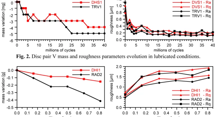
Some interruptions of the twin disc tests were made for measuring contact surface roughness and topography, mass loss (due to wear) and surface residual stresses, to follow their evolution during the rolling contact fatigue process. An example of the mass and roughness parameters evolution of the discs tested is presented in Fig. 2 and 3, for lubricated and dry conditions. The contact surfaces of the tested specimens were also observed by optical microscopy during twin disc tests interruptions to verify the existence of defects, such as cracks, pits or spalls. The contact surfaces state, after testing, is shown in Fig. 4 and 5. The twin disc rolling contact fatigue tests performed in wheel and rail materials allowed to conclude that under the tested conditions the running-in phase of the studied materials ends after approximately 5 million rotations, and rolling contact fatigue cracks appear at the contact surface after 15 to 18 million cycles in lubricated conditions. It was verified, during lubricated tests, that the wheel material is more sensitive to defects initiation, since the larger number of defects was observed in the wheel specimens. However, during dry tests no defect was
detected, probably due to the high wear rate that removes any crack that appears at the contact surface. The wheel material presents a higher wear rate than the rail material, which is more noticeable in dry tests. This difference in the wear rate is the cause of the corrugations observed in the contact surfaces of the discs tested in dry conditions (Fig. 5), due to the fact that the used twin disc machine imposes the same rotating speed in the two discs and if one has higher wear it’s diameter will be different than the other disc, consequently the tangential speed of the two discs on the contact will be different and sliding is verified. No significant influence of the extraction position of discs from the real wheel and rail profiles was detected on the results.
Fig. 2. Disc pair V mass and roughness parameters evolution in lubricated conditions.
Fig. 3. Disc pair VIII mass and roughness parameters evolution in dry conditions.
Fig. 4. Contact surfaces after 40×106 cycles in lubricated conditions.
Fig. 5. Contact surfaces after 0.8×10⁶ cycles in dry conditions.
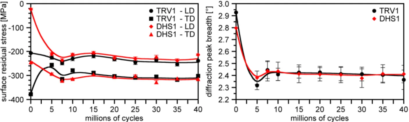
The evolution of the residual stresses at the discs' surface, during rolling contact fatigue, are shown in Fig. 6, as well as the evolution of the X-ray diffraction peak breadth. These experimental results show an evolution of the surface during the lubricated rolling contact fatigue tests, pointed out by gradual changes of the residual stress state and the X-ray diffraction peak breadth values, mainly during the running-in phase. The surface residual stresses are always compressive for both types of discs and more intense in the transversal direction, compared to longitudinal. But after the running-in we obtain a stabilized residual stress state, where the stresses are very similar for the same direction in both types of discs. The initial stress state at the surface, however, is not the same on the discs obtained from the wheel and the rail, as it can be seen in Fig. 6, due to the fact that the sequence of machining and finishing operations where not the same for the cylindrical and ‘spherical’ discs.
The in-depth residual stresses and X-ray diffraction peak breadth depth results, obtained after electro polishing layer removal, can be observed in Fig. 7, corresponding to the state before rolling contact fatigue and after 40 millions cycles. Before rolling contact fatigue tests, the specimens present an initial residual stress state in the surface layers essentially due to the machining and finishing of the specimens surface, since they were not submitted to any post-machining treatment. They present large compressive stresses near the surface, with transversal residual stresses of higher magnitude than the longitudinal stresses, followed by tensile stresses at a depth between 30 and 120 µm. After 40 millions cycles we can see that, as a result of the accumulation of plastic microdeformation during cyclic stressing under rolling contact loading conditions, the initial tensile stresses at greater depth are changed to compressive. The rolling contact loading develop large compressive residual stresses in both directions within a surface layer with more than 700 µm, which drastically changed the initial residual stress state introduced by the machining of the discs and is in agreement with other results found in the literature [8-14]. Two different effects of the rolling contact fatigue can be observed: (i) the higher values at the extreme surface, induced by the direct action of the contact, and (ii) maximums of compressive residual stresses at a depth of 400 µm and of the X-ray diffraction peak breadth distribution at a depth of about 200 µm, that should be related to the action of the maximum in-depth hertzian stresses.
Fig. 6. Residual stresses determined in the longitudinal direction (LD) and the transversal direction
(TD) of the rolling track and X-ray diffraction peak breadth evolution at the discs’ pair V surface.
Fig. 7. Residual stress determined in the longitudinal direction (LD) and the transversal direction
(TD) of the rolling track and X-ray diffraction peak breadth depth profiles before rolling contact fatigue (wheel disc RAD1 - before fatigue testing) and after 40×106 cycles (wheel disc TRV1).
Concluding remarks
In the present experimental conditions, the running-in phase of both wheel and rail materials ends after approximately 5 million cycles and rolling contact fatigue defects appear at the contact surface after 15 to18 million cycles in lubricates conditions. The wheel material presents a higher wear rate than the rail material and is more sensitive to defect initiation. However, during dry tests no defect was detected, probably due to the high wear rate that removes any crack that appears at the contact surface. The experimental results show an evolution of the surface integrity during contact
fatigue tests, which was confirmed by the gradual changes in the residual stresses values, mainly during the running-in phase. The rolling contact fatigue introduces compressive stresses, with the higher values at the extreme surface and a maximum at a certain depth that should be related to the action of the in-depth hertzian stresses. A more complete analysis of the evolution of residual stress fields in the twin disc machine specimens will be assessed and their influence on the evolution of initial surface cracks will be better understood.
Acknowledgements
D.F.C. Peixoto acknowledges a Calouste Gulbenkian Foundation PhD grant, number 104047-B. The authors acknowledge the financial support of the Portuguese Government through "FCT Fundação para a Ciência e a Tecnologia" and the European Union program FEDER through "Programa Operacional Factores de Competitividade - COMPETE" under the projects PTDC/EME-PME/100204/2008 “Railways” and Pest C/FIS/UI0036/2011. The wheel was kindly supplied by ALSTOM Spain. The rail was kindly supplied by REFER through the Civil Engineering Department of the Faculty of Engineering of the University of Porto. The collaboration of Mr. A.A.L. Rego in the update of the twin-disc machine is acknowledged.
References
[1] Atlas of Wheel and Rail Defects: A Report Commissioned by the Steering Group of UIC/WEC Joint Research Project 2 - Wheel/Rail Interface Optimization, International Union of Railways, UIC, 2004.
[2] W. Zhong, J.J. Hu, Z.B. Li, Q.Y. Liu, Z.R. Zhou, A study of rolling contact fatigue crack growth in U75V and U71Mn rails, Wear. 271 (2011) 388-392.
[3] W.J. Wang, H.M. Guo, X. Du, J. Guo, Q.Y. Liu, M.H. Zhu, Investigation on the damage mechanism and prevention of heavy-haul railway rail, Engineering Failure Analysis. 35 (2013) 206-218.
[4] A. Ekberg, E. Kabo, Fatigue of railway wheels and rails under rolling contact and thermal loading - an overview, Wear. 258 (2005) 1288-1300.
[5] D.F.C. Peixoto, L.A.A. Ferreira, Fatigue crack propagation behavior in railway steels, International Journal of Structural Integrity. 4, 4 (2013) 487-500.
[6] A.A.L. Rego, D.F.C. Peixoto, L.A.A. Ferreira, Rolling contact fatigue tests in a twin disc machine, Proceedings of IBERTRIB 2011, VI Iberian Congress on Tribology, Madrid, Spain, 16-17 June. (2011).
[7] K.L. Johnson, Contact Mechanics, Cambridge University Press, Cambridge, 1985.
[8] E.V. Zaretsky, R.J. Parker, W.J. Anderson, A Study of Residual Stress Induced During Rolling, Journal of Tribology. 91, 2 (1969) 314-318.
[9] H. Muro, N. Tsushima, K. Nunome, Failure analysis of rolling bearings by X-ray measurement of residual stress, Wear. 25, 3 (1973) 345–356.
[10] A.P. Voskamp, R. Österlund, P.C. Becker, O. Vingsbo, Gradual changes in residual stress and microstructure during contact fatigue in ball bearings, Metals Technology. 7 (1980) 14–21. [11] A.P. Voskamp, E.J. Mittemeijer, State of residual stress induced by cyclic rolling contact
loading, Materials Science and Technology. 13, 5 (1997) 430-438.
[12] R. C. Dommarco, K. J. Kozaczek, P. C. Bastias, G. T. Hahn, and C. A. Rubin, Residual stresses and retained austenite evolution in SAE 52100 steel under non-ideal rolling contact loading, Wear. 257, 11 (2004) 1081-1088.
[13] L. Coelho, A.M. Dias, H.P. Lieurade, H. Maitournam, Experimental and Numerical Rolling Contact Fatigue Study on the 32 CrMoV 13 Steel, Fatigue Fract Engng. Mater. Struct., 27 (2004) 811-823.
[14] B. Allison, G. Subhash, N. Arakere, D.A. Haluck, H. Chin, Influence of Initial Residual Stress on Material Properties of Bearing Steel During Rolling Contact Fatigue, Tribology Transactions. 57 (2014) 533-545.
Residual Stresses IX
10.4028/www.scientific.net/AMR.996
X-Ray Diffraction Residual Stress Measurements for Assessment of Rolling Contact Fatigue Behaviour of Railway Steels
10.4028/www.scientific.net/AMR.996.782
DOI References
[14] B. Allison, G. Subhash, N. Arakere, D.A. Haluck, H. Chin, Influence of Initial Residual Stress on Material Properties of Bearing Steel During Rolling Contact Fatigue, Tribology Transactions. 57 (2014) 533-545.