ISSN 0101-2061 Food Science and Technology
DI:
D http://dx.doi.org/10.1590/1678-457X.0027
1 Introduction
Supercritical fluid technology embodies processes that are performed at pressures and temperatures near or above the critical point of a substance. In the early 1970s, the most popular application was supercritical fluid extraction (SFE), which is often referred to as gas extraction (Brunner, 1994) because of the use of carbon dioxide (CD2) at pressures and temperatures above the critical point (304.2 K and 73.8 bar). Knowledge of the capacity of some condensable gases to solubilize a variety of chemicals is well documented in the literature. For CD2, it has been well documented since the publication of the solubility of several compounds in liquid CD2 by Francis (1954).
Supercritical fluid technology is viable at an industrial scale for several applications. Nonetheless, to date, the most popular application is SFE from solid matrices. The extraction of bioactives from several plants is an attractive field; currently, in Brazil, conventional methods of extraction are practiced at the industrial level. Nonetheless, there is a richness of research being done in the field of SFE by the Brazilian and Latin American scientific communities (Moraes et al., 2014). However, there are only a few semi-industrial units in Brazil and Latin America; these units have extractors of up to 12 liters, i.e., they are of small
size compared to the industrial units that are in operation in Asia, North America and Europe. However, experimental data should be used to scale up the process. As discussed by Meireles (2003), small-sized extractors (up to 50 mL) can provide data for selecting the process conditions, such as temperature and pressure. A very careful determination of the extract’s chemical composition is required to choose the conditions under which the target compound or a mixture of target compounds is obtained. Then, a very preliminary economic feasibility study should be done. To obtain such data, one can use commercial or homemade SFE units. To the best of our knowledge, the first experimental SFE unit in Brazil was assembled by Meireles & Germer (1992). Since then, several other SFE units have been assembled in LASEFI/DEA/FEA/UNICAMP, as reported in the literature (Ferreira at al., 1993; Pasquel et al., 2000; Santos & Meireles, 2013; Zabot et al., 2014).
The installation of homemade equipment for supercritical extraction with CD2 at a laboratory scale should be a versatile project that is applicable to various raw materials at different extraction conditions, with at least two separators, and should
Construction of a supercritical fluid extraction (SFE) equipment: validation using
annatto and fennel and extract analysis by thin layer chromatography coupled to image
Júlio Cezar Flores JDHNER1, Maria Angela de Almeida MEIRELES1*
Received 30 Sept., 2015 Accepted 05 Feb., 2016
1 Laboratório de Tecnologia Supercrítica Extração, Fracionamento e Identificação de Extratos Vegetais – LASEFI, Departamento de Engenharia de Alimentos – DEA, Faculdade
de Engenharia de Alimentos – FEA, Universidade Estadual de Campinas – UNICAMP, Campinas, SP, Brazil
*Corresponding author: [email protected]
Abstract
The present work describes setting up a laboratory unit for supercritical fluid extraction. In addition to its construction, a survey of cost was done to compare the cost of the homemade unit with that of commercial units. The equipment was validated using an extraction of annatto seeds’ oil, and the extraction and fractionation of fennel oil were used to validate the two separators; for both systems, the solvent was carbon dioxide. The chemical profiles of annatto and fennel extracts were assessed using thin layer chromatography; the images of the chromatographic plates were processed using the free ImageJ software. The cost survey showed that the homemade equipment has a very low cost (~US$ 16,000) compared to commercial equipment. The extraction curves of annatto were similar to those obtained in the literature (yield of 3.8% oil). The separators were validated, producing both a 2.5% fraction of fennel seed extract rich in essential oils and another extract fraction composed mainly of oleoresins. The ImageJ software proved to be a low-cost tool for obtaining an initial evaluation of the chemical profile of the extracts.
Keywords: supercritical fluid extraction; homemade extraction unit; annatto; fennel; thin layer chromatography; ImageJ software.
Practical Application: A low-cost (~US$ 16,000) homemade supercritical fluid extraction (SFE) unit for the determination of
allow for adaptations throughout the research to improve functioning (Martínez & Vance, 2008).
Considering that CD2 reservoirs’ (laboratory bottles’) pressures are between 50 and 60 bar, supercritical extraction equipment at a laboratory scale should contain a thermostatic bath with a coil in its reservoir to cool the CD2 and ensure that it is in the liquid phase during pumping (Brunner, 1994; Zetzl et al., 2003). In this way, the auxiliary pumping system for the chilled fluid, which is usually a solution of ethylene glycol, may be used to cool the last separator and help retain more volatile compounds, thereby guaranteeing a higher purity of the CD2 evaporated at the end of the extraction line and thus facilitating solvent recovery (Reverchon, 1997).
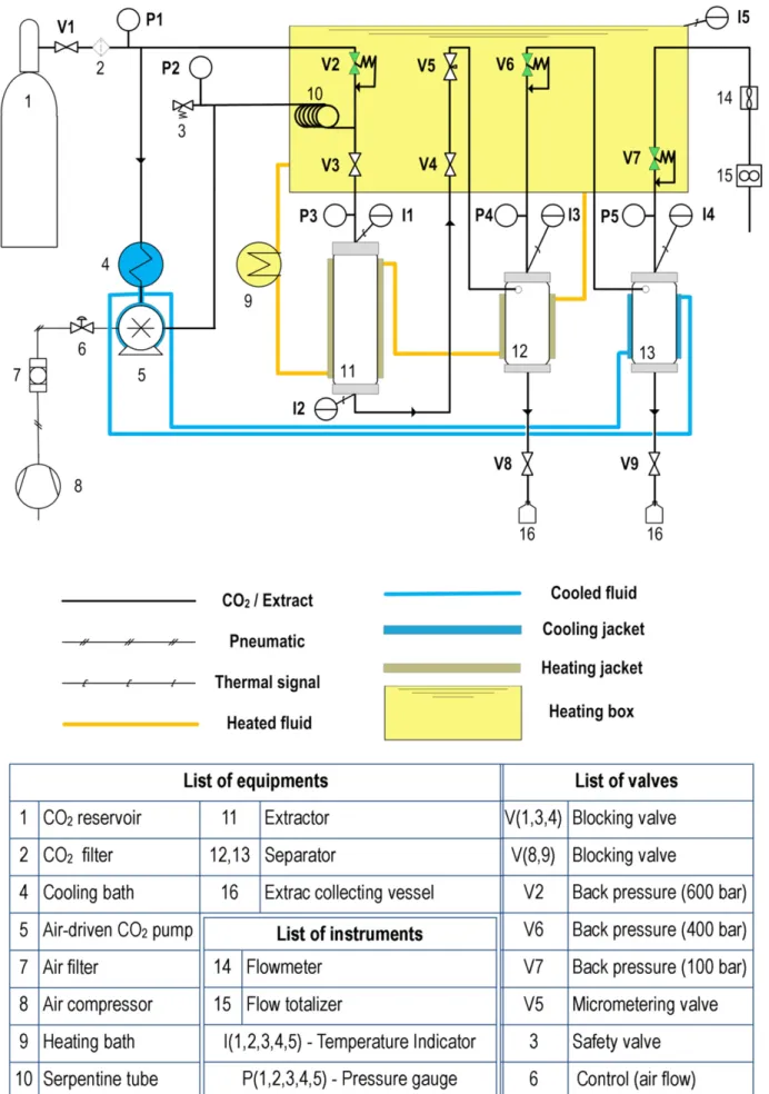
Another component of supercritical extraction equipment that may provide a dual function is the heating bath. It is used to heat the CD2 after pumping, thus keeping it in the supercritical fluid condition, and is used as an auxiliary system to heat the extractor and first separator jackets, as shown in Figure 1 (Zetzl et al., 2003).
Using this strategy, which makes the heating and cooling components multipurpose, the cost of the thermal exchange components in laboratory units may represent only 20% of the total equipment costs. A limiting factor of this strategy is that because the equipment will have only one source for heating and cooling, the temperatures must be set to the closest values of the CD2 pumping conditions and vegetable matrix extraction.
For assembling the various components of the supercritical extraction equipment, 30 × 30 × 6000 mm aluminum profiles, angle bars and screws may be used. These structures are light and adjustable to the needs of the projects, have low acquisition costs and represent only 1.7% of the total installation cost.
Considering the need for supercritical extraction equipment to obtain high-quality extracts without a large initial equipment investment, there was a need for a low-cost SFE unit for use in the development of processes. Then, in 1999, a cooperative project between Brazil (CNPq 910016/99-2) and Germany (Ministry of Research and Education BMBF DLR-IB, BRA 098/78) provided the funds to construct four identical low-cost SFE units at approximately US$ 15,000 each (all taxes included). In Brazil, the following laboratories were involved: LASEFI/DEA/FEA/UNICAMP, LATESC/EQA/CT/UFSC, and LADS/FEQ/CT/UFPA. In Germany, the laboratory involved was Arbeitsbereich Thermische Verfahrenstechnik (Technical University Hamburg-Harburg (TUHH). The homemade, low-cost units were used extensively in all four laboratories. After 14 years, the SFE unit of LASEFI was remodeled. The purpose of this paper is to make the construction details widely available to the scientific community and to describe the processes that were used to validate the equipment. To validate the equipment, two raw materials for which experimental data are available in literature were used (Albuquerque & Meireles, 2012; Coelho et al., 2003; Moraes et al., 2015; Moura et al., 2005; Reverchon et al., 1999; Simándi et al., 1999). The two materials have different characteristics: (i) annatto (Bixa orellana L.) has the presence of a lipidic fraction that is rich in tocotrienols and a terpenic fraction containing geranilgeraniol, and (ii) sweet fennel (Foeniculum
vulgare) contains a lipidic fraction and a terpenic fraction, but in this case, formed by a mixture of terpenes (Moura et al., 2005).
2 Materials and methods
The SFE-TUHH was designed and built at the “Thermische Verfahrenstechnik” Laboratory of Professor Gerd Brunner at TUHH – Technische Universitat Hamburg-Harburg – in 2002. The following parts from this equipment were used to assemble the renovated SFE unit, now denoted as SFE-0.1L: the extractor, the separators and part of the heating and cooling systems (Zetzl et al., 2003).
The SFE-0.1L unit was intended to facilitate the control of the pressures on the separators, to modernize process indicators and to develop a new support structure for the equipment components that was less susceptible to corrosion. The original SFE-TUHH design was maintained.
2.1 Equipment setup
Before starting the renovation of the SFE-TUHH, a list of needed parts was prepared (Table 1). Table 1 lists all of the components used to assemble the SFE-0.1L; the cost of each piece is also presented.
The first step in constructing the SFE-0.1L unit was the assembly of the component support structure using aluminum profiles (30 × 30 × 6000 mm) (SISTEMA, 30 × 30 series, Amparo, Brazil), caps, brackets, screws, bolts and 2 mm stainless steel plates and casters. The main frame of SFE-0.1L contains 4 pieces of 800 mm, 5 pieces of 710 mm and 7 pieces of 510 mm These pieces units were attached to the primary structure (Figures 2-4). The two steel plates were assembled based on the dimensions of the previously described structure profiles; that is, (770 × 570 × 2 mm) and (300 × 420 × 2 mm). Subsequently, all of the components were located with the objective of easy access to the extractor, separators, valve panel and process indicators. The 1/8-inch stainless steel tubing (Fopil, ASTMA269S, Campinas, Brazil) was folded and reinserted into the structure by connecting the points, in accordance with the flow diagram in Figure 5.
Following the installation of the tubing using the connections and components in Figure 5, thermal insulation was installed. The silicon hoses and their insulation were connected to the heating and cooling components.
The valve box was constructed of stainless steel to avoid corrosion from constant contact with the heating fluid, with 22-mm connections to facilitate fluid output flow. The insulation, similar to all of the heating and cooling components, was made using a 3-mm-thick elastomeric blanket (Epex, Vidoflex M2, Blumenau, Brazil).
In this way, when the system is over pressure, the pressure valve adjusts, with recycling keeping constant pressure in the extractor. The Maximator M 111 Series pump used to install the SFE-0.1L unit was fixed as close to the thermostatic bath as possible.
Pressurization tests were done on the extraction cells after the equipment was installed. The pressure cells were filled with glass beads and subjected to 350-bar pressure for a static time of 20 minutes, followed by a flow period with solvent flow rate of 15 g/min for 30 minutes. This was done to test the pump’s
functioning and to evaluate possible oscillations in the pressure and temperature during the process (Appendix A).
The positioning of the components in the unit prioritized the functionality of the equipment in such a way that all process indicators were visible, easily managed and in front of the operator (Appendix B).
the output of the micrometering valve with the external part of the valve panel, thus allowing the extracts to be collected immediately after extraction (Appendix D).
2.2 Equipment validation
To validate the equipment, two raw materials, annatto and sweet fennel, were used. The annatto was used to validate the extraction line without the use of the separators, and the fennel was used to validate the extraction followed by separation.
2.3 Raw materials preparation
The annatto seeds were acquired at the Estação do Grão Ltda. (São Paulo, Brazil) and stored at 255 K. They were packed into the extractor without any further preparation, as indicated by Silva et al. (2008), Albuquerque & Meireles (2012) and Moraes et al. (2015).
The fennel seeds were acquired in the municipal market of Campinas, Brazil at “Temperos Brasil” and kept at 255 K. The fennel seed preparation procedure was adapted from the Table 1. SFE-0.1L Estimated Cost and Components.
Product Name Qty Price Total (USD)
Extractor 100 mL* 1 748.40 748.40
Separator 90 mL* 2 916.80 1,833.61
Jacket* 3 100.03 300.09
Valve box (Maq’nagua, Serra Negra, Brazil) 1 157.23 157.23
Aluminum plate (m2) (Autic, Campinas, Brazil) 3 30.50 91.51
Aluminum profile 6 m (Sistema, 30 × 30 series, Amparo, Brazil) 8.5 11.32 96.23
Angle (Sistema, 30 × 30 series, Amparo, Brazil) 40 1.57 62.89
Square nut and screws (Sistema, 30 × 30 series, Amparo, Brazil) 150 0.68 101.42
End cap (Sistema, 30 × 30 series, Amparo, Brazil) 8 0.79 6.29
Swivel caster (Colson, 3”, Araucária, Brazil) 4 6.92 27.67
Manometer* (WIKA, EN8371-1, Klingenberg, Alemanha) 5 341.19 1,705.97
Safety valve (Swagelok, SS-4R3AS, São Paulo, Brazil) 1 237.23 237.23
Temperature indicator (Pyrotec, T4WM-TP100, Campinas, Brazil) 1 190.25 190.25
Termocouple (Pyrotec, TP100, Campinas, Brazil) 5 20.35 101.73
Flowmeter (Cole Parmer, PMR1, IL, USA) 1 336.48 336.48
Flow totalizer (Itrón, G25, Americana, Brazil) 1 40.88 40.88
Tubing 1/8” (6 m) (Fopil, ASTMA269S, Campinas, Brazil) 2 89.62 179.25
Ferrule 1/8” (Fopil, Campinas, Brazil) 10 3.24 32.42
Connector Tee DD 1/8” (Fopil, ASTMA276, Campinas, Brazil) 8 44.30 354.39
Connector Tee side NPT 1/4” (Fopil, A.276316, Campinas, Brazil) 4 20.13 80.50
Connector DD-DD (Fopil, ASTMA269TP316S, Campinas, Brazil) 3 20.12 60.35
Connector DD-NPT (Fopil, ASTMA269TP316S, Campinas, Brazil) 2 11.80 23.60
CD2 filter (Swagelok, F series, São Paulo, Brazil) 1 96.38 96.38
Blocking valve (Autoclave Engineers, 10V2071, PA, USA) 5 165.17 825.83
Micrometering valve (Autoclave Engineers, 10VRM2812, PA, USA) 1 466.53 466.53
Back pressure valve (Tescon, 44-1800, Sorocaba, Brazil) 1 366.04 366.04
Back pressure valve (Tescon, 44-2200, Sorocaba, Brazil) 1 602.91 602.91
Back pressure valve (Tescon, 26-1700, Sorocaba, Brazil) 1 1,550.33 1,550.33
Air pressure regulator (Norgren, R07-100-RNKA, São Paulo, Brazil) 1 100.94 100.94 Air-driven CD2 pump (Maximator, M-111L, Nordhausen, Germany) 1 1,861.64 1,861.64
Heating bath (Thermo Haake, DC30/DL30, Eindhoven, Holanda) 1 1,532.84 1,532.84
Cooling bath (Thermo Haake, C10, Eindhoven, Holanda) 1 1,691.82 1,691.82
Ball valve (Japi, ball, Jundiaí, Brazil) 2 7.36 14.72
Hose npt adapter (Amanco, Campinas, Brazil) 2 3.46 6.92
Hose connector 90 elbow (Elgo, 1203, Itu, Brazil) 1 1.73 1.73
Insulation tube Ø - 1/8” (m) (Armaflex, AFM-10, Campinas, Brazil) 1 1.83 1.83
Insulation sheets (Epex, Vidoflex M2, Blumenau, Brazil) 0.6 24.45 14.67
Insulation tube Ø - 22 mm (Isolan, Campinas, Brazil) 5 0.94 4.72
Plastic tee conector (Amanco, Campinas, Brazil) 4 1.96 7.83
Silicone hose (5 m) (Sinergia, 200 × 200, Campinas, Brazil) 1 22.17 22.17
work of Moura et al. (2005), with the frozen seeds being ground in a mill (Marconi, model 340, São Paulo, Brazil) using a 3-mm sieve into 20-g batches. To characterize the average particulate diameter by the standard method of ASABE (American Society of Agricultural and Biological Engineers, 2008), an electromagnetic agitator was used (Bertel, model 602, São Paulo, Brazil) with screens of the Tyler mesh series (16, 24, 32, 48 and 80 mesh). The prepared seeds were then packed into the extractor.
2.4 Extraction and separation
The extractor of the SFE-0.1L unit has a volume of 100 mL and an internal height/diameter relationship of 19 (HB/DB = 19). The two separators have a 90 mL volume, with a tangential entrance equipped with thermocouples that reach half the height of the cylinder, allowing estimates of the wall boundary conditions and of the temperatures at the central points of the cylinders.
For annatto and fennel, the solvent used was carbon dioxide (99% purity, White Martins, Brazil); the bath was set at 268 K to assure CD2 in the liquid phase at the pump entrance. The extractor
pressure was 200 bar, and the temperature was 313 K according to the procedure used by Moraes et al. (2015), with a flow rate of 23.7 g/min and 60 g feeding into the extractor. The extracts were collected immediately after the micrometering valve using glass flasks that were also connected to the flowmeter (Cole Parmer, PMR1, IL, USA) and then to the flow totalizer (Itrón, G25, Americana, Brazil). The ratio of the mass of solvent to the feed mass (S/F) was comparable to the extraction curve of the SFE-0.1L unit for the annatto extraction data of the SFE-2×1L unit, built and validated at LASEFI/DEA/FEA/UNICAMP (Zabot et al., 2014).
diffusion of solute from the solid structures defines the mass transfer rate (Meireles, 2008). The overall extraction curve (DEC) was adjusted to a spline model containing three straight lines using the SAS 9.2® software according to the steps described by Meireles (2008) and Zabot et al. (2014).
Fennel extract was obtained at 200 bar and 313 K according to the procedure used by Reverchon et al. (1999), with a flow rate of 12 g/min and S/F of 10. The conditions in separators 1 (80 bar, 312 K) and 2 (20 bar, 279 K) were adapted from the works of Coelho et al. (2003) and Simándi et al. (1999). After 60 minutes of extraction, the extracts were stored at 255 K for later analyses.
2.5 Analyses of extracts
Annatto extracts: Extracts were analyzed using Thin Layer Chromatography (TLC). A bixin standard was prepared according to the procedure performed by Albuquerque & Meireles (2012), using a Shaker Incubator (Marconi, MA420, São Paulo, Brazil) in which annatto seeds were exhaustively extracted with acetone for 6 h (200 rpm, 298 K). TLC plates (Macherey-Nagel DC-Fertigfolien Alugram®, XTSILG, Darmstadt, Germany) were used; the mobile phase was hexane:ethyl acetate:formic acid (79:18:3), as optimized by Albuquerque (2013). For fennel extracts, the TLC plates (Macherey-Nagel DC-Fertigfolien Alugram®, XTSILG/UV254, Darmstadt, Germany) were used; the mobile phase was toluene:ethyl acetate (6:4), as described by Wagner & Bladt (2001).
The pattern of bixin (3 µL) was applied 3 times on the chromatographic plate to test the repeatability of the method, and 6 points of this pattern with different masses of bixin (0.6, 1.2, 2.4, 4.8, 9.6 and 19.2 µg) were applied on the same plate to evaluate the linearity of the developed method.
The pattern of bixin (3 µL) was inserted at the first point of the plate, followed by the extracts of annatto that were collected at selected extraction times. The extracts (1 µL) were inserted directly onto the plates based on the increasing sequence of extraction times. The plates were photographed with and without the developer AS - anisaldehyde sulfuric acid reagent – and heated for 5 min at 383 K using a tank equipped with a UV lamp: Short Wave (254 nm) - Long Wave (366 nm) – (Entela, UVGL-58, USA).
The fennel extracts obtained from the first and second separator were diluted with toluene in the proportion extract:toluene (1:1); 1 µL of the extract was used (extract in separator-1) with 3 repeated applications of 1 µL for the extract from separator-2. The eluted plates were photographed in a tank equipped with a UV light (254 and 366 nm). The plates were heated for 5 min at 383 K before and after spraying with concentrated sulfuric acid developer.
The images of the chromatographic plates were processed using the free ImageJ software (Ferreira & Rasband, 2010). A location with adequate illumination for the possible points was prepared first, so the areas of the plate with less illumination would not influence the images. A standard photodocumentation height, the point where the plate was placed and the point where
the machine would be positioned to take photos, was selected. The camera was fixed using a support consisting of a stand with handles, with the lens and the TLC plate remaining parallel and at a distance of 30 cm. Subsequently, the photos were opened in ImageJ by the command <File-Dpen>. A plate without any extract was tested to evaluate the efficiency of the photodocumentation system, aiming for an image with a standard open surface plane using the Interactive 3D Surface Plot tool.
ImageJ was used to calculate the “Ratio to Front” (Rf) of the plates, first testing to find the best way to visualize the bands on the plate. By selecting the command <Edit-Invert> to invert the colors of the plate and comparing the result with the original colors of the image, this tool may provide a more accurate measurement, even for compounds that are present at low concentrations or for those with coloration bands close to the intensity of the pixels on the bottom of the plate.
The best image for measuring the Rf of each compound was determined by the commands <*Straight*, segmented of freehand lines - Analyze - Measure (Results) - Analyze - Label>, which were repeated until all necessary measurements were obtained. During the measurement, the lines were traced without deviating from the slope of the straight line; that information was provided along with the results of the measurements.
The areas of the peaks were calculated to estimate the effect of different bixin concentrations on the method validation curve and to evaluate the bixin content present in each sample of the annatto extracts. The images had a rectangular section of the same Rf selected, and the areas in the pixels of the compounds were calculated using the tools <*Rectangular* - Analyze - Gels - Select First Lane - Analyze - Gels - Plot lanes (Plots) - Wand (Tracing) tool (Results, Area)>.
The 3D surfaces of the bands of the different compounds were plotted using the tools <*Rectangular* - Analyze - Gels - Select first lane - Plugins - 3D - Interactive 3D Surface Plot - Select: Filled, (Driginal Colors, Spectrum LUT or Thermal LUT) and adjusted Grid Size, Smoothing, Perspective, Lighting, Invert, Scale, Z-Scale, Max and Min>.
3 Results and discussion
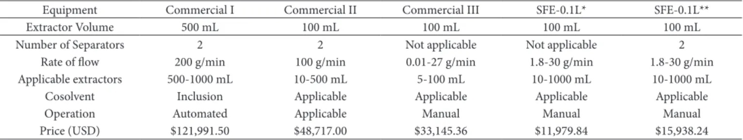
The equipment represented an initial cost of US$ 15,938.24 with the separators and US$ 11,979.84 with the extractor only, using the secondary extraction line (Table 2). The extraction and separation cells, valves and thermostatic baths constituted 60% of the total setup cost of the equipment.
The comparison between the costs of acquisition and setup of the laboratory equipment for extraction with supercritical fluid is the principal result of this work, demonstrating that the design of the SFE unit resulted in low-cost equipment.
Non-automated units have lower acquisition costs relative to automated equipment. For example, Commercial unit II may be automated for an additional US$ 10,850.00 (Table 2).
Comparing the commercial unit of lowest cost, Commercial unit III, to the SFE-0.1L unit without the separators (for both to have the same functionality), the cost of the homemade equipment was 36% of the cost of the commercial unit. Another advantage of the assembly process compared to purchasing commercial equipment is that each project may be adjusted in accordance with the peculiarities of the research objective that will be addressed when using the equipment.
3.1 Equipment setup
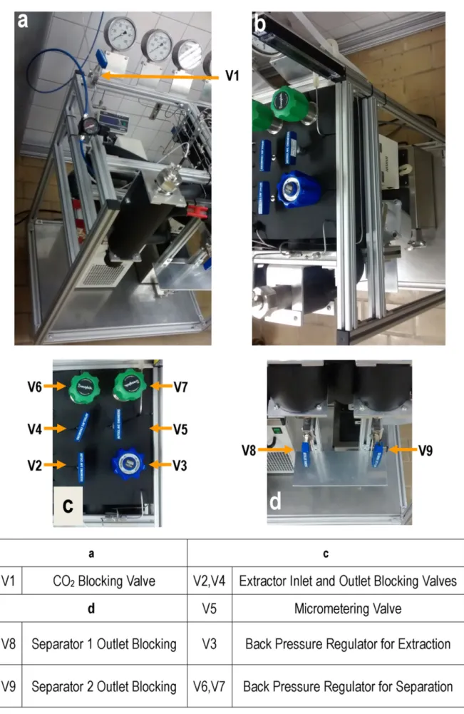
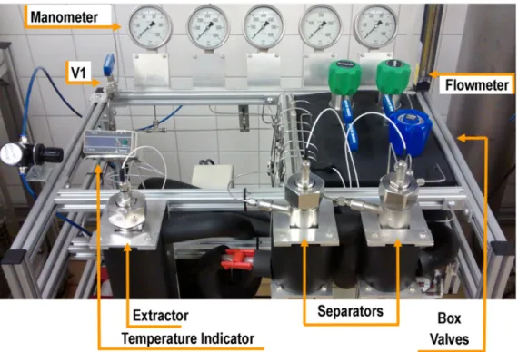
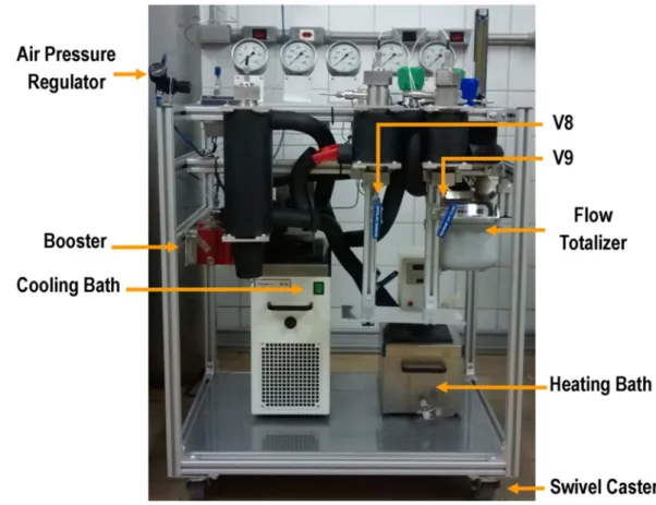
Figures 6 and 7 show the SFE-0.1L unit and the component positioning in the aluminum structure. Casters were placed on the lower part of the aluminum structure to facilitate moving the equipment for potential maintenance.
The assembly of the two component support plates could have been achieved with 5-mm-thick aluminum plates to facilitate plate perforation to place their fixing screws. The aluminum plates are light, cost less and easy to handle; moreover, they can support the weight of the two baths in the lower part of the unit and the valve box in the upper part of the unit. Though other materials may be used to support the structural components, stainless steel plates were used in this project because of the availability of this material in our laboratory.
In the lower part of the separators, it is possible to observe an adjustable support for extract collection that occurs sequentially in the V7 and V8 shut-off valves. In this way, it is possible to adjust the height of the support in accordance with the type of bottle that will be used in the extract collection process and to release the extract output by opening only valves V7 and V8.
The extraction and separation cells were aligned with the most external part of the structure and were positioned with the indentation at the front of the structure. This helped reduce
the final size of the equipment and the length of the pipes. The equipment measures 57 × 77 × 115 cm.
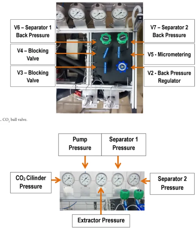
Another important aspect of the SFE-0.1L unit is that all of the system valves, including the additional valves, such as a backpressure valve for each separator, make it possible to control the cascade of pressures in the separators; the micrometering valve allows control of the solvent flow rate. The use of a backpressure valve for each pressure cell allows precise control of the working pressures. The system that heats the valves using a fluid-flow heat exchanger proved more efficient than the use of electric resistances. The unit has a safety valve that opens at pressures higher than 450 bar, positioned as shown in Figure 5, immediately after the pump and with the relief directed to the rear of the equipment.
3.2 Equipment validation
Extractor validation using annatto seeds
The extraction yield of the annatto in the SFE-0.1L unit was 3.8%, comparable to the work of Albuquerque & Meireles (2012), who determined a yield of 3.7%. After 15 minutes of extraction, 74% of all annatto extract was collected; nonetheless, the extraction continued for 80 minutes to complete depletion of the raw material (Figure 8-I). The elevated flow rate (12 g/min) used to validate the equipment resulted in an S/F of 37 at the end of extraction.
Figure 8-II shows the experimental values for extraction performed in the SFE-2×1L (Moraes et al., 2013) and in the SFE-0.1L, plotted as a function of S/F. Though the extractors were 10 times farther apart, the results validated the SFE-0.1 unit because of the overlap of the DECs.
The annatto DEC (Figure 8-I and 8-II) can be fitted to a spline with 3 straight lines ((Meireles, 2008), as shown in Figure 8; the adjusted parameters are given in Table 3. With these results, the SFE-0.1L unit can be considered validated. The SFE-0.1L unit can be expanded to a unit with an extractor of up to 1 liter by adjusting only the supports and the thermal shielding.
Table 2. Comparison of the amounts spent assembling the SFE-0.1L unit relative to the cost of acquiring commercial units.
Equipment Commercial I Commercial II Commercial III SFE-0.1L* SFE-0.1L**
Extractor Volume 500 mL 100 mL 100 mL 100 mL 100 mL
Number of Separators 2 2 Not applicable Not applicable 2
Rate of flow 200 g/min 100 g/min 0.01-27 g/min 1.8-30 g/min 1.8-30 g/min
Applicable extractors 500-1000 mL 10-500 mL 5-100 mL 10-1000 mL 10-1000 mL
Cosolvent Inclusion Applicable Applicable Applicable Applicable
Dperation Automated Applicable Manual Manual Manual
Price (USD) $121,991.50 $48,717.00 $33,145.36 $11,979.84 $15,938.24
*SFE-0.1L unit assembled without separators. **SFE-0.1L unit assembled with two separators.
Table 3. Parameters from Annatto Extraction Curve.
b0 b1 b2 b3 c1 c2 SS
Values 0.015 0.4868 0.0597 0.014 4.4435 18.046 0.0203
Validation of the separators using fennel
The commercial equipment from Thar Technologies (model SFE-2×5LF-2-FMC, Pittsburgh, PA, USA) has 2 extractors of 5 liters and 3 separators with volumes of approximately 500 mL. Considering the possibility of using a larger capacity extractor in the SFE-0.1L unit, the separators were designed with volumes of 90% of that of the extractors. The reasoning behind this choice was to ensure that the separators would hold as much extract, in terms of capacity, as would be obtained from a raw material with up to 30% of solute. Considering that, on average, each 100 mL extraction cell may contain approximately 70 grams of
raw material for a 3.8% yield, approximately 2.7 grams of extract would be obtained. Dtherwise, for a raw material having 30% of soluble material using a 1-liter extractor capable of processing 700 g of raw material, the extract mass would be ~ 270 grams. Therefore, in this case, the separators must be capable of holding this amount of extract, and separators of approximately 100 mL would be required. This estimate takes into account the fact that the extract is continuously collected. Therefore, for the SFE0.1L unit, 90 mL separators were used, representing 90% of the capacity of the extractor; the larger capacity of the separators thus leaves open the possibility of using a larger extractor.
Another important aspect to be considered in the setup of the equipment is that many of the raw materials have a group of majoritarian components. In other words, the division of the extract in the separators may only be 3% for one of the groups of compounds; therefore, the other 97% should be retained in the other separator. The work of Coşge et al. (2008) evaluated the composition of the sweet fennel seed oil and found that sweet fennel has a relationship of 93:3 of oleoresin:essential oil.
There are little data in the literature on the separator volume compared to the extractor’s capacity, and the actual construction of equipment at laboratory scale can now serve as an initial parameter for pilot-scale applications.
The fennel extraction in the SFE0.1L unit resulted in a yield of 2.8% (g extract/100 g of ground seeds). As discussed in the next section, this extract mass contained 97.5% of a lipidic fraction collected in the first separator; the remaining 2.5% was the volatile oil collected in the second separator. Stefanini et al. (2006) determined yields of 1.54 to 2.2% using hydrodistillation to obtain fennel volatile oil; both the yield and composition varied with the crop conditions. The higher yield obtained in this work is because CD2 extracts the lipidic fraction in addition to the volatile oil.
3.3 Analyses of extracts
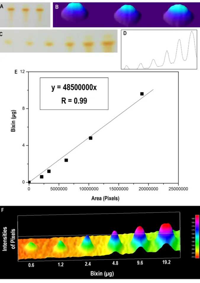
The method used to determine the bixin concentration showed linearity for concentrations between 0.6 to 9.6 µg, as shown in Figure 9E, and had a repeatability that varied by 3.4%, as observed by comparing the areas of the pixels of Figures 9A and 9B.
In Figure 10, the presence of bixin is observed in all of the extracts collected during the extraction; nonetheless, it is important to acknowledge that annatto extract contains other carotenoids that are present in the seeds (Mercadante & Pfander, 2001). Although TLC is a technique that is used mainly in qualitative analysis, it is possible to observe a tendency for the
bixin concentration to increase throughout extract collection at an Rf of 0.1, as shown in Figure 10A and plotted in Figure 11. In a similar manner, Albuquerque et al. (2015) found an increase in bixin concentration as a function of extraction time.
Validating the bixin quantification method by TLC using the ImageJ software made it possible to estimate the carotenoid concentration as a function of the extraction time. In this way, in addition to polling by separation of the present compounds, it was possible to estimate the bixin extraction curve.
Albuquerque & Meireles (2012) obtained annatto extract using a commercial SFE unit Spe-ed (Laboratory System 7071, Applied Separation, Allentown, USA) with a 0.29 L extractor. The data obtained from the extraction on the SFE-0.1L unit with the same raw material is an additional important aspect in validating the equipment: not only was a similar DEC determined, but the extract composition during the extraction was also similar to that obtained in the commercial unit (Figure 8).
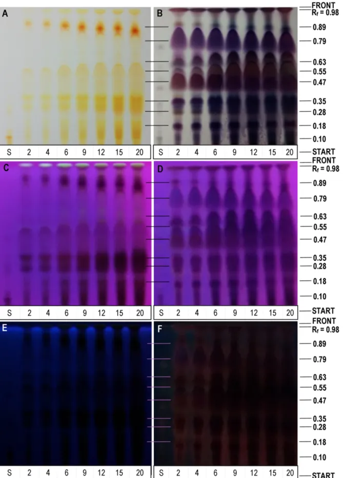
In the images of Figure 10, the Rf of 0.98 for all of the annatto extracts showed some distinct pixel intensities on the plate at 366 nm and 245 nm and, with the use of the reagent AS, revealed the presence of these compounds in all of the samples in the visible range. The type of fluorescence of image C is not characteristic of either terpenoids or polyphenols (Wagner & Bladt, 2001). The plate without developer presented an increased Rf concentration with increasing extraction time, which may indicate that there are different compounds eluted in this same Rf, characteristic because they have less affinity with the mobile phase hexane:ethyl acetate:formic acid (79:18:3).
For the Rf 0.89 and 0.55 (Figure 10A), the concentration of the compounds increased with extraction time; the same behavior was observed at Rf of 0.10 and 0.35 for the plate in Figure 10B.
Figure 9. Validation steps of the bixin determination method. (A) Image of plate chromatography refers to method repeatability; (B) Image
A manipulated with ImageJ (Interactive 3D Surface Plot - Thermal LUT); (C) Image of the chromatographic plate refers to method linearity; (D) Image C manipulated with ImageJ (Plot Lanes); (E) Graphic of bixin concentrations by areas of the pixels obtained by ImageJ; (F) Image C
Figure 10. Image of the chromatographic plates obtained from the elutions of the extracts from the kinetic points of Figure 8 (Lower codes: S - Bixin Standard and the respective numbers in minutes on the kinetic points). Photo A (Without Developer - Visible), photo B (With Developer - Visible), photo C (Without Developer - 366 nm), photo D (With Developer - 366 nm), photo E (Without Developer - 254 nm) and photo F
The fennel extracts collected (Figure 12) in Separator 1 (I) and Separator 2 (II) have different compositions. The chromatography plate shows the different compositions of the extracts retained in each separator. The blade (*) plotted on the 3D surface reinforces the differences in extract compositions, where (*) Rf = 0.43 corresponds to the fenchone present in the extract obtained in Separator II.
The method of Wagner & Bladt (2001) for developing volatile oils using concentrated sulfuric acid found that the fenchone to be sprayed should be revealed by a yellowish coloration at Rf ~ 0.5, if it is present at concentrations higher than 100 µg. After the chromatographic plate was sprayed with this reagent, the plate presented a coloration close to that of fenchone, which is difficult to visualize at low concentrations. However, by using the Invert tool in ImageJ, which inverts image colors, it is possible to more clearly identify the compound.
the quantity of compounds in the visible range for the annatto extracts, with the blue, green, red and brown colorations being characteristic of the essential oils (Wagner & Bladt, 2001); this confirms the presence of geranilgeraniol in annatto extracts.
Figure 11. Image selected from Figure 10A (Rf = 0.1) manipulated with ImageJ (Interactive 3D Surface Plot - Driginal Colors).
Figure 12. Images of the chromatogrpahic plates and of the extracts obtained from the fennel seeds from separators I and II. Photo A (Without developer - 254 nm), photo B (With developer - Visible), photo C (With Developer - 366 nm), photo D (Image B* manipulated ImageJ - Interactive 3D Surface Plot - Driginal Colors), photo E (Image D manipulated with ImageJ - Invert), photo F (Extracted from the first separator) and photo
Brunner, G. (1994). Gas extraction: an introduction to fundamentals
of supercritical fluids and the application to separation processes.
New York: Springer. http://dx.doi.org/10.1007/978-3-662-07380-3. Coelho, J. A. P., Pereira, A. P., Mendes, R. L., & Palavra, A. M. F. (2003). Supercritical carbon dioxide extraction of Foeniculum vulgare volatile oil. Flavour and Fragrance Journal, 18(4), 316-319. http:// dx.doi.org/10.1002/ffj.1223.
Coşge, B., Kiralan, M., & Gürbüz, B. (2008). Characteristics of fatty acids and essential oil from sweet fennel (Foeniculum vulgare Mill. var. dulce) and bitter fennel fruits (F. vulgare Mill. var. vulgare) growing in Turkey. Natural Product Research, 22(12), 1011-1016. http://dx.doi.org/10.1080/14786410801980675. PMid:18780240. Ferreira, S. R. S., Meireles, M. A. A., & Cabral, F. A. (1993). Extraction
of essential oil of black pepper with liquid carbon dioxide. Journal of
Food Engineering, 20(2), 121-133.
http://dx.doi.org/10.1016/0260-8774(93)90010-H.
Ferreira, T., & Rasband, W. (2010). The ImageJ User Guide: IJ 1.45. Retrieved from imagej.nih.gov/ij/docs/guide/
Francis, A. W. (1954). Ternary systems of liquid carbon dioxide. Journal
of Physical Chemistry, 58(12), 1099-1114. http://dx.doi.org/10.1021/
j150522a014.
Martínez, J. L., & Vance, S. W. (2008). Supercritical extraction plants equipment, process, and costs. In J. L. Martinez (Ed.), Supercritical
fluid extraction of nutraceuticals and bioactive compounds (pp.
25-28). Boca Raton: CRC Press.
Meireles, M. A. A. (2003). Supercritical extraction from solid: process design data (2001-2003). Current Opinion in Solid State and
Materials Science, 7(4-5), 321-330. http://dx.doi.org/10.1016/j.
cossms.2003.10.008.
Meireles, M. A. A. (2008). Extraction of bioactive compounds from latin american plants. J. L. Martinez (Ed.), Supercritical fluid extraction
of nutraceuticals and bioactive compounds. Boca Raton: CRC Press.
Meireles, M. A. A., & Germer, S. P. M. (1992). Extração de produtos naturais com fluidos pressurizados: subcríticos e supercríticos. In
Anais da III Mostra Interna de Trabalhos Científicos em Andamento,
Campinas, SP.
Mercadante, A. Z., & Pfander, H. (2001). Caracterização de um novo carotenóide minoritário de urucum. Food Science and Technology, 21(2), 193-196.
Moraes, M. N., Zabot, G. L., & Meireles, M. A. A. (2013). Assembling of a supercritical fluid extraction equipment to operate in continuous mode. In Proceedings oh the III Iberoamerican Conference on
Supercritical Fluids Cartagena de Indias, Colombia.
Moraes, M. N., Zabot, G. L., & Meireles, M. A. A. (2014). Applications of supercritical fluids in latin america: past, present and future trends.
Food and Public Health, 4(3), 162-179. http://dx.doi.org/10.5923/j.
fph.20140403.11.
Moraes, M. N., Zabot, G. L., & Meireles, M. A. A. (2015). Extraction of tocotrienols from annatto seeds by a pseudo continuously operated SFE process integrated with low-pressure solvent extraction for bixin production. The Journal of Supercritical Fluids, 96, 262-271. http:// dx.doi.org/10.1016/j.supflu.2014.09.007.
Moura, L. S., Carvalho, R. N. Jr, Stefanini, M. B., Ming, L. C., & Meireles, M. A. A. (2005). Supercritical fluid extraction from fennel (Foeniculum vulgare): global yield, composition and kinetic data.
The Journal of Supercritical Fluids, 35(3), 212-219. http://dx.doi.
org/10.1016/j.supflu.2005.01.006.
Pasquel, A., Meireles, M. A. A., Marques, M. D. M., & Petenate, A. J. (2000). Extraction of stevia glycosides with CD2 + water, CD2 + ethanol, and
Df the 2.8% yield of fennel extract, 97.5% was a waxy extract collected in the first separator, and 2.5% was an oily extract collected in the second separator. As observed in Figure 12 in the images of extracts I and II, these extracts presented distinct visual characteristics, with these being the first indicators showing the effectiveness of the separators. The work of Coşge et al. (2008) analyzed the oil of sweet fennel and found 3% essential oil, with anethole, estragole and fenchone being the predominant components of this fraction, and found 93% of monounsaturated fatty acids in the oleoresin fraction.
The extract collected in the first separator is formed by an oleoresin that also contains red-violet anisaldehyde, Rf = 0.39, and anethole, Rf = 0.87. The extract from the second separator is formed exclusively by essential oils and presented fenchone, Rf = 0.43 (Figure 12E), and two other compounds, Rf = 0.53 (Figure 12A) and Rf = 0.11 (Figure 12B).
4 Conclusions
The assembled equipment may be used as a standard for a low-cost SFE unit for the formulation of projects to construct new extraction units. The extractor is adequate for use in obtaining extracts of diverse raw materials, and its separators can function to obtain fractionated extracts. The validated method for bixin quantification and the procedure adapted for the production of a bixin pattern represent a low-cost option for annatto extract analysis. The description of the use of the free ImageJ software may be adapted for analysis of other images that need precise measurements, whether they are intended to calculate Rf or not, such as the use of the tools to calculate areas from parts of images.
Acknowledgements
The authors thank CNPq for the financial support provided and the free software ImageJ for support in image manipulation. Júlio C. Johner F. thanks CNPq (140287/2013-2) for the doctoral scholarship. M. A. A. Meireles acknowledges the productivity grant from CNPq (301301/2010-7).
References
Albuquerque, C. L. C. (2013). Obtenção de sementes desengorduradas e de óleo rico em tocotrienóis de urucum por extração supercrítica: estudo dos parâmetros de processo, do aumento de escala e da
viabilidade econômica (Master’s thesis). Universidade Estadual de
Campinas, Campinas.
Albuquerque, C. L. C., & Meireles, M. A. A. (2012). Defatting of annatto seeds using supercritical carbon dioxide as a pretreatment for the production of bixin: experimental, modeling and economic evaluation of the process. The Journal of Supercritical Fluids, 66, 86-95. http:// dx.doi.org/10.1016/j.supflu.2012.01.004.
Albuquerque, C. L. C., Santana, Á. L., & Meireles, M. A. A. (2015). Thin layer chromatographic analysis of annatto extracts obtained using supercritical fluid. Food and Public Health, 5(4), 127-137. http:// dx.doi.org/10.5923/j.fph.20150504.05.
American Society of Agricultural and Biological Engineers – ASABE. (2008). Method of determining and expressing fineness of feed materials
Simándi, B., Deák, A., Rónyai, E., Yanxiang, G., Veress, T., Lemberkovics, E., Then, M., Sass-Kiss, A., & Vámos-Falusi, Z. (1999). Supercritical carbon dioxide extraction and fractionation of fennel oil. Journal of
Agricultural and Food Chemistry, 47(4), 1635-1640. http://dx.doi.
org/10.1021/jf9809535. PMid:10564030.
Stefanini, M. B., Ming, L. C., Marques, M. D. M., Facanali, R., Meireles, M. A. A., Moura, L. S., & Sousa, L. A. (2006). Essential oil constituents of different organs of fennel (Foeniculum vulgare var.vulgare).
Revista Brasileira de Plantas Medicinais, 8, 193-198.
Wagner, H., & Bladt, S. (2001). Plant drug analysis: a thin layer
chromatography atlas (2nd ed.). Berlin: Springer.
Zabot, G. L., Moraes, M. N., & Meireles, M. A. A. (2014). Influence of the bed geometry on the kinetics of rosemary compounds extraction with supercritical CD2. The Journal of Supercritical Fluids, 94(0), 234-244. http://dx.doi.org/10.1016/j.supflu.2014.07.020.
Zetzl, C., Brunner, G., & Meireles, M. A. A. (2003, April 28-30).
Standardized low-cost batch SFE-units for University education and comparative research. In Proceedings of 6th International Symposium
on Supercritical Fluids, Versailles, France.
CD2 + water + ethanol. Brazilian Journal of Chemical Engineering, 17(3), 1-16. http://dx.doi.org/10.1590/S0104-66322000000300003. Reverchon, E. (1997). Supercritical fluid extraction and fractionation
of essential oils and related products. The Journal of Supercritical
Fluids, 10(1), 1-37. http://dx.doi.org/10.1016/S0896-8446(97)00014-4.
Reverchon, E., Daghero, J., Marrone, C., Mattea, M., & Poletto, M. (1999). Supercritical fractional extraction of fennel seed oil and essential oil: experiments and mathematical modeling. Industrial
& Engineering Chemistry Research, 38(8), 3069-3075. http://dx.doi.
org/10.1021/ie990015+.
Santos, D. T., & Meireles, M. A. A. (2013). Micronization and encapsulation of functional pigments using supercritical carbon dioxide. Journal of Food Process Engineering, 36(1), 36-49. http:// dx.doi.org/10.1111/j.1745-4530.2011.00651.x.
Appendix A. SFE-0.1L Unit Standard Dperating Procedures (SDPs). Campinas-SP, July of 2015.
Standard Operating Procedure
Knowledge of all the components of the unit is an important step in operating the equipment. SFE-0.1L unit consists of the following:
• 1 structure formed by aluminum profile 30 × 30 mm (Sistema, Amparo, Brazil)
• 2 swivel casters without brakes connected to the structure (Colson, 3”s, Araucária, Brazil)
• 2 swivel casters with brakes connected to the structure (Colson, 3”c, Araucária, Brazil)
• 1 aluminum plate (Autic, Campinas, Brazil) that serves as the foundation for the heating and cooling baths (770 × 570 × 2 mm)
• 1 stainless steel plate that serves as the foundation for the valve box with heating system (Maq’nagua, Serra Negra, Brazil)
• 1 valve panel formed by a stainless steel plate with a size of 320 × 270 × 2 mm (Maq’nagua, Serra Negra, Brazil)
• 1 heating valve box (310 × 260 × 120 mm) for the valve panel with fluid inlet and outlet with diameter of 22 mm (Maq’nagua, Serra Negra, Brazil)
• 1 backpressure valve (Tescon, 26-1700, Sorocaba, Brazil)
• 1 backpressure valve (Tescon, 44-2200, Sorocaba, Brazil)
• 1 backpressure valve (Tescon, 44-1800, Sorocaba, Brazil)
• 1 air pressure regulator (Norcren, R07-100-RNKA, São Paulo, Brazil)
• 1 safety valve (Swagelok, SS-4R3AS, São Paulo, Brazil)
• Tube adapter, tube DD 1/8” e NPT female 1/4” (Swagelok, SS-400-6-2, São Paulo, Brazil)
• 1 air-driven CD2 pump (Maximator, M-111L, Nordhausen, Germany)
• Tube 1/8” DD of 0.89 mm length (Fopil, A.I.ASTMA269TP316S, Campinas, Brazil)
• Tube adapter - Union Tee Connector, tube DD 1/8” with ferrule (Fopil, ASTMA276TP316, Campinas, Brazil)
• Tube adapter - Straight Union, tube DD 1/8” with ferrule ASTM A276TP316 (Fopil, A.I.ASTMA269TP316S, Campinas, Brazil)
• Tube adapter - tube DD 1/8” e NPT Male 1/4” ASTM A276TP316 (Fopil, A.I.ASTMA269TP316S, Campinas, Brazil)
• Tube adapter - union tee male branch NPT 1/4” (Fopil, ASTMA276TP316, Campinas, Brazil)
• Cylinder outlet connection (Hoke 7115F4Y, Spartamburg, EUA)
• Blocking valve (Autoclave Engineers, 10V2071, PA, USA)
• Micrometering valve (Autoclave Engineers, 10VRMM2812, PA, USA)
• Particulate filter (Swagelok, série F, São Paulo, Brazil)
• 2 pressure gauge - 100 bar (WIKA, EN8371-1, Klingenberg, Germany)
• 2 pressure gauge - 600 bar (WIKA, EN8371-1, Klingenberg, Germany)
• 1 pressure gauge - 400 bar (WIKA, EN8371-1, Klingenberg, Germany)
• Insulation sheets - 13 mm (Epex, Vidoflex M2, Blumenau, Brazil)
• 1 temperature indicator 173.2 K — 473.0 K (Pyrotecautomação, T4WM-TP100, Campinas, Brazil)
• 3 thermocouples - 50 mm × 1.2 m (Pyrotecautomação, PT 100, Campinas, Brazil)
• 2 thermocouples - 150 mm × 1.2 m (Pyrotecautomação, PT 100, Campinas, Brazil)
• 1 separator with heating jacket, 90 mL
• 1 separator with cooling jacket, 90 mL
• 1 extractor with heating jacket, 100 mL
• 2 ball valve (Japi, globo, Jundiaí, Brazil)
• Flowmeter (Cole Parmer, PMR1, IL, USA)
• Flow totalizer (Itrón, G25, Americana, Brazil)
• Silicone hose (Sinergia, 200 × 200, Campinas, Brazil)
• Insulation tube 1/8” (Armaflex, AFM-10, Campinas, Brazil)
• Insulation tube Ø - 22 mm (Isolan, Campinas, Brazil)
• 2 serpentine tubes 1/8”
• 1 hose serpentine
• 1 steel plate (420 × 350 × 2 mm)
• 2 hose npt adapter (female 22 mm) 1/2” (Amanco, Campinas, Brazil)
• 2 Hose Tee connector 1/2” (Amanco, Campinas, Brazil)
• 1 extractor support structure (Autic, Campinas, Brazil)
• 4 separators support structures (Autic, Campinas, Brazil)
• 1 aluminum plate 110 x 270 x 5 mm (Autic, Campinas, Brazil)
• 1 heating bath (1500 W) 243 K — 373 K (Thermo Haake, C10, Eindhoven, Holland)
• 1 cooling bath (2000 W) 278 K — 368 K (Thermo Haake, DC30/DL30, Eindhoven, Holland)
Each topic presented in the SDP is numbered according to the sequence of the unit operational steps and may be followed by the underlined word “Caution”, with an explanation of what should be checked.
Standard procedure to turn on and operate the SFE-0.1L unit
1) Turn on the air conditioning of the extraction room for approximately 10 minutes before starting work on the unit to operate at constant room temperature; record this value;
2) Record the value of the flow totalizer (Figure 1A);
3) Connect the power cables of the temperature indicator, thermostatic bath and heating bath in voltage and amperage indicated in the plugs (Figures 1A and 2A);
4) Record the temperature of the temperature indicator (Figure 2A); 5) Release the pressure of the compressed air to the regulator (Figure 1A); 6) Close the blocking valve V1 (Figure 2A);
7) Dpen the CD2 cylinder valve and the ball valve of the cylinder connector that carries the CD2 to the tubes (Figure 3A); 8) Close the blocking valve V3 (Figure 4A);
9) Turn on the thermostatic bath until it reaches operating temperature. The maximum working temperature must be 268 K and the minimum 255 K. The thermostatic bath takes approximately 45-60 minutes to reach the temperature;
10) Disconnect the 1/8” tube of the hose t connector connected to the upper part of the extractor with a 55 mm wrench with a movement of 90° counterclockwise; after this rotation no longer use the wrench, but finish with the hands (Figure 5A). Caution: If is not possible to finish opening using the hands, the thread has been damaged. Send the cover and the thread for repair before it is no longer possible to open it using a 55 mm wrench. To open the unit cell, it must be under internal pressure conditions similar to the environment to prevent damage to their threads. The covers are made of the same material as the threads, and they could be caught in the thread if torque were applied with a key while the cell was pressurized. At the slightest sign of trouble while opening, send the parts for repair;
11) Place the desired raw material inside the extractor;
12) Place the Teflon gasket into the cell and then screw the cover with your hands until the point where is necessary to use the wrench. Place the center output of the hose’s T connector that connects the cover to the tubing and the thermocouple with a 45 ° angle relative to the tube that connects the 1/8 tube (Figure 5A). Exert torque on the cover clockwise with a 55 mm wrench until the connection aligns with the 1/8” tubing and screw the tubing into the hose’s T connector;
13) Dpen the blocking valve V1; the cylinder manometer pressure should reach 60 bar (Figure 6A), in case the cylinder is full. (Dnly use the cylinder with pressure between 60 and 50 bar);
14) Before turning on the heating bath (Figure 1A), the water level should be checked. Additionally, observe if the water is clean (Figure 7A); because the jacket is made of copper, the fluid should be periodically changed to avoid rusting of the thermocouple, which could affect the temperature control. Indeed, some dirty particles could damage the pump of this component. Caution: The fluid level of the heating bath should be higher than the black plastic connected to the tube and always lower than the cover of this component (Figure 7A). If the fluid level is not between the indicated positions, the bath will turn off automatically and the fluid will return to the valve panel, causing an overflow. To avoid this inconvenience, two ball valves at the base of the bath pump output (Figure 8A) and a type of hose valve with an open body were installed;
15) Turn on the heating bath. (This heating bath interchanges thermal energy with the extractor jacket, with the jacket of the first separator and with the valve panel). Because of the specifications of the backpressure valves, the maximum temperature of the heating bath should be 353 K. Check that the bath temperature reaches the desired temperature in the extractor. If necessary during the extraction, regulate the bath temperature to keep the temperature of the thermocouple at the extractor outlet constant;
Figure 3A. CD2 ball valve.
Figure 5A. Extractor components. (a) CD2 inlet 1/8 tube; (b) Extractor - 55 mm; and (c) Teflon.
16) Then, pressurize the tube that connects the air-driven CD2 pump to the valve V3. Slowly release the air pressure to the air-driven CD2 pump, which should begin to move its piston at 2.5 bar of pressure with the pump regulator gauge (Figure 1A). Because the backpressure valve is still fully open, the pressure should not rise in the second manometer and the flow corresponding to the excess pressure should be recirculated to the tubing before the air-driven CD2. At this point, the backpressure valve should start to slowly close; the pressure in the second manometer will rise. The air-driven CD2 pump should begin to pressurize (pump) slowly and then more pressure should be liberated from the compressed air regulator until the desired pressure is reached and the CD2 is recycled by the backpressure valve. (Caution: the air-driven CD2 pump should work constantly to avoid pressure changes in the compressed air that cause changes in the extractor pressure. Thus, after the initial adjustment, the equipment should work constantly until the end of the extraction process without the need for controlling the pressure of the compressed air or the back pressure, Figure 4A);
Figure 7A. Bath level. (a) Full mark, do not overfill; (b) Add mark, add water when level is at or below this mark.
17) Dnce the pump has been working constantly for some seconds, recycling the flow corresponding to the excess pressure after the pump, the blocking valve V4 should be closed (Figure 4A). Then, slowly open the blocking valve (Figure 4A) until the pressures in the extraction and pump manometers are the same. Caution: Do not open the blocking valve V3 suddenly; if this happens, the pressure after the air-driven CD2 pump will fall sharply and it will pump unevenly, which may cause undesired operation;
18) Count 20 minutes of static time;
19) The micrometering valve V5 must be closed carefully. Do not close it totally and damage its needle. Caution: The micrometering valve should never be completely closed; for this reason, a blocking valve is installed in the same line for the sole purpose of performing this function. In this way, when the blocking valve is opened, the micrometering valve V5 is already in the working position and only requires an initial adjustment to maintain the flow rate;
20) After the static time and with the micrometering valve already adjusted to control the flow (this point corresponds to approximately 45° of rotation before the flow is blocking; never completely close the valve to avoid damaging the needle), release the blocking valve V3;
21) Record the beginning of the extraction time;
22) At this time, the flow adjustment should be performed only through the micrometering valve to keep it constant during the entire process. Caution: Considering that the fluid should pass across two separators before entering the flowmeter, a few seconds are spent before observing some change in the flowmeter caused by a position change in the micrometering valve. To avoid damage to the needle, it is necessary to wait for the response in the flowmeter before adjusting the valve V5 again (Figure 4A). Then, wait for approximately 15 seconds to evaluate if the flow in the flowmeter is constant;
23) Dnce the flow rate has been regulated, begin to close the backpressure valve V6; this valve should be closed by turning it clockwise 45° until the desired pressure in the manometer is reached (Figure 6A). Caution: This sort of valve has better precision when it is closing than when it is opening; thus, do not pressurize the system beyond the working pressure;
24) Then repeat the procedure described in 23) with the backpressure valve V7, which should be regulated with less pressure than the first separator. Never use excessive torque on any valve, especially on the backpressure valves; their springs are very sensitive and approximately 1200 ° rotation is enough to reach pressures of 200 bar;
25) Following the specified procedures, the unit should be operated without the necessity for any adjustment. If there is some variation in the flowmeter, repeat 22) to 24) while the extracts are being stored in the separators.
SFE-0.1L unit shutdown procedure:
1) Dnce the extraction time is finished, close the blocking valve V4 (Figure 4A);
2) Close the compressed air feeding valve (Figure 1A); 3) Close the blocking valve V3 (Figure 4A);
4) Close the CD2 cylinder valve (Figure 4A);
5) Turn off the thermostatic bath (Figure 1A); 6) Record the flow totalizer value (Figure 1A);
7) The pressure should fall in the extractor when the air-driven CD2 pump has stopped. Then carefully open the valves V4 and V5, trying to maintain a constant flow rate, to depressurize the system. Dnce the extractor pressure is the same as that in the first separator, open the micrometering valve V5 totally;
8) Gradually open the backpressure valve V6, maintaining the flowmeter at the same process flow rate until the pressures equalize in both separators;
9) Gradually open the back pressure valve V7, maintaining the flowmeter at the same process flow rate until 5 bar is reached in the three cells, extractor, separator 1 and 2;
10) Recover the extracts using proper flasks, previously weighed; 11) Adjust the collector base extract based on the flask height;
Appendix B. SFE-0.1L Standard Dperating Procedures (SDPs) of the Secondary Extraction Line. Campinas-SP, July of 2015
Standard Operating Procedures (SOPs) for the secondary extraction line
To perform studies in the SFE-0.1L unit without using the separators or if the objective is to build the unit without installing the separators, a secondary extraction line was developed. This line consists of a 1/8” tube connected to the outlet of the micrometering valve that should be inserted into a collecting flask connected after the flowmeter and flow totalizer.
Figure 1B shows the tube used in the procedure, with an angle to allow the tube to exit the valve panel; the extract is thus recovered. The details of the secondary extraction line are shown in Figure 2B; all equipment components are arranged in a flow diagram.
14) Dpen the 1/8” tubing that connects with the hose T connector. The pressure will fall to the ambient pressure. With the extractor still warm, open the top cover and remove the raw material;
15) Turn off the heating bath and immediately close both blocking valves at the pump outlet (Figure 8A) to avoid heating fluid reflux;
16) Perform the cleaning procedure described in the SFE-0.1L Unit Standard Cleaning Procedure; 17) Disconnect the power cables of the temperature indicator, thermostatic bath and heating bath.
Standard Operating Procedure
The knowledge of all unit components is a key factor in proper operation of the equipment. The secondary extraction line consists of the following:
• 1 structure formed by an aluminum profile 30 × 30 mm (Sistema, Amparo, Brazil)
• 2 swivel casters without brakes connected to the structure (Colson, 3”s, Araucária, Brazil)
• 2 swivel casters with brakes connected to the structure (Colson, 3”c, Araucária, Brazil)
• 1 aluminum plate (Autic, Campinas, Brazil) that serves as the foundation for the heating and cooling baths (770 × 570 × 2 mm);
• 1 stainless steel plate that serves as the foundation for the valve box with heating system (Maq’nagua, Serra Negra, Brazil)
• 1 valve panel formed by a stainless steel plate of size of 320 × 270 × 2 mm (Maq’nagua, Serra Negra, Brazil)
• 1 heating valve box (310 × 260 × 120 mm) for the valve panel with fluid inlet and outlet with diameter of 22 mm (Maq’nagua, Serra Negra, Brazil)
• 1 backpressure valve (Tescon, 26-1700, Sorocaba, Brazil)
• 1 backpressure valve (Tescon, 44-2200, Sorocaba, Brazil)
• 1 backpressure valve (Tescon, 44-1800, Sorocaba, Brazil)
• 1 air pressure regulator (Norcren, R07-100-RNKA, São Paulo, Brazil)
• 1 safety valve (Swagelok, SS-4R3AS, São Paulo, Brazil)
• Tube adapter, tube DD 1/8” e NPT female 1/4” (Swagelok, SS-400-6-2, São Paulo, Brazil)
• 1 air-driven CD2 pump (Maximator, M-111L, Nordhausen, Germany)
• Tube 1/8” DD 0.89 mm (Fopil, A.I.ASTMA269TP316S, Campinas, Brazil)
• Tube adapter - Union Tee Connector, tube DD 1/8” with ferrule (Fopil, ASTMA276TP316, Campinas, Brazil)
• Tube adapter - Straight Union, tube DD 1/8” with ferrule ASTM A276TP316 (Fopil, A.I.ASTMA269TP316S, Campinas, Brazil)
• Tube adapter - tube DD 1/8” e NPT Male 1/4” ASTM A276TP316 (Fopil, A.I.ASTMA269TP316S, Campinas, Brazil)
• Tube adapter - union tee male branch NPT 1/4” (Fopil, ASTMA276TP316, Campinas, Brazil)
• Cylinder outlet connection (Hoke 7115F4Y, Spartamburg, EUA)
• Blocking valve (Autoclave Engineers, 10V2071, PA, USA)
• Micrometering valve (Autoclave Engineers, 10VRMM2812, PA, USA)
• Particulate filter (Swagelok, séria F, São Paulo, Brazil)
• 2 pressure gauges - 100 bar (WIKA, EN8371-1, Klingenberg, Germany)
• 2 pressure gauges - 600 bar (WIKA, EN8371-1, Klingenberg, Germany)
• 1 pressure gauge - 400 bar (WIKA, EN8371-1, Klingenberg, Germany)
• Insulation sheets - 13 mm (Epex, Vidoflex M2, Blumenau, Brazil)
• 1 temperature indicator 173.2 K — 473.0 K (Pyrotecautomação, T4WM-TP100, Campinas, Brazil)
• 3 thermocouples - 50 mm × 1.2 m (Pyrotecautomação, PT 100, Campinas, Brazil)
• 2 thermocouples - 150 mm × 1.2 m (Pyrotecautomação, PT 100, Campinas, Brazil)
• 1 separator with heating jacket, 90 mL;
• 1 separator with cooling jacket, 90 mL
• 1 extractor with heating jacket, 100 mL;
• 1 ramp clamp (Keck SK, Max. tubing o.d. 1/4 in. / 6 mm, Munich, Germany)
• Flowmeter (Cole Parmer, PMR1, IL, USA)
• Flow totalizer (Itrón, G25, Americana, Brazil)
• Silicone hose (Sinergia, 200 × 200, Campinas, Brazil)
• Insulation tube 1/8” (Armaflex, AFM-10, Campinas, Brazil)
• Insulation tube Ø - 22 mm (Isolan, Campinas, Brazil)
• 2 serpentine tube 1/8”;
• 1 serpentine hose;
• 1 steel plate (420 × 350 × 2 mm);
• 2 hose npt adapters (female 22 mm) 1/2” (Amanco, Campinas, Brazil)
• 2 Hose Tee connectors 1/2” (Amanco, Campinas, Brazil)
• 1 extractor support structure (Autic, Campinas, Brazil)
• 4 separators support structures (Autic, Campinas, Brazil)
• 1 aluminum plate 110 x 270 x 5 mm (Autic, Campinas, Brazil)
• 1 heating bath (1500 W) 243 K — 373 K (Thermo Haake, C10, Eindhoven, Holland)
• 1 cooling bath (2000 W) 273 K — 368 K (Thermo Haake, DC30/DL30, Eindhoven, Holland)
Each topic presented in the SDP is numbered according to the sequence of the unit operational steps, and may be followed by the underlined word “Caution” with the explanation of what should be checked.
Standard procedure to turn on and operate the SFE-0.1L unit with the secondary extraction line:
26) Turn on the air conditioning of the extraction room for approximately 10 minutes before starting work on the unit to operate at constant room temperature; record this value;
27) Record the value of the flow totalizer (Figure 3B);
28) Connect the power cables of the temperature indicator, thermostatic bath and heating bath in voltage and amperage indicated in the plugs (Figures 3B and 4B);
29) Record the temperature of the temperature indicator (Figure 4B);
30) Release the pressure of the compressed air to the regulator (Figure 3B); 31) Close the blocking valve V1 (Figure 4B);
32) Dpen the CD2 cylinder valve and the ball valve of the cylinder connector that carries the CD2 to the tubes (Figure 5B); 33) Close the blocking valve V3 (Figure 6B);
34) Turn on the thermostatic bath until it reaches operating temperature. The maximum working temperature must be 268 K and the minimum 255 K. The thermostatic bath takes approximately 45-60 minutes to reach the temperature;
35) Disconnect the 1/8” tube of the hose t connector connected to the upper part of the extractor with a 55 mm wrench with a movement of 90° counterclockwise; after this rotation no longer use the wrench but finish with the hands (Figure 7B). Caution: If is not possible to finish opening using the hands the thread was damaged; send the cover and the thread for repair before it is no longer possible to open it using a 55 mm wrench. To open the unit cell, it must be in internal pressure conditions similar to the environment to prevent damage to their threads. The covers are made of the same material as the threads, and they could be caught into the thread if torque were applied with a key while the cell is pressurized. At the slightest sign of trouble during the opening, send the parts for repair;
36) Place the desired raw material inside the extractor;
Figure 3B. Unit SFE-0.1L, front view.
38) Dpen the blocking valve V1; the cylinder manometer pressure should reach 60 bar (Figure 8B), in case the cylinder is full (only use the cylinder with pressure between 60 and 50 bar);
39) Before turning on the heating bath (Figure 3B), the water level should be checked. Additionally, observe if the water is clean (Figure 9B); because the jacket is made of copper, the fluid should be periodically changed to avoid rusting of the thermocouple, which could affect the temperature control. Indeed, some dirty particles could damage the pump of this component. Caution: The fluid level of the heating bath should be higher than the black plastic connected to the tube and should always be lower than the cover of this component (Figure 9B). If the fluid level is not between the indicated positions, the bath will turn off automatically and the fluid will return to the valve panel, causing overflow. To avoid this inconvenience, two ball valves at the base of the bath pump output (Figure 10B) and a type of hose valve with an open body were installed; Figure 5B. CD2 ball valve.
40) Turn on the heating bath. (This heating bath interchanges thermal energy with the extractor jacket and with the valve panel). Because of the specifications of the backpressure valves, the maximum temperature of the heating bath should be 353 K. Check that the bath temperature reaches the desired temperature in the extractor. If necessary during the extraction, regulate the bath temperature to keep the temperature of the thermocouple at the extractor outlet constant;
41) Then, pressurize the tube that connects the air-driven CD2 pump to the valve V3. Slowly release the air pressure to the air-driven CD2 pump, which should begin to move its piston at 2.5 bar of pressure with the pump regulator gauge (Figure 3B). Because the backpressure valve is still fully open, the pressure should not rise in the second manometer and the flow corresponding to the excess pressure should be recirculated to the tubing before the air-driven CD2. At this point, the backpressure valve should start to slowly close, and the pressure in the second manometer will rise. The air-driven CD2 pump should begin to pressurize (pump) slowly and then more pressure should be liberated from the compressed air regulator until the desired pressure is reached and the CD2 is recycled by the backpressure valve. (Caution: the air-driven CD2 pump should work constantly to avoid pressure changes in the compressed air that cause changes in the extractor pressure. Thus, after the initial adjustment, the equipment should work constantly until the end of the extraction process without the need for controlling the pressure of the compressed air or the back pressure, Figure 6B);
42) Dnce the pump has been working constantly for some seconds, recycling the flow corresponding to the excess pressure after the pump, the blocking valve V4 should be closed (Figure 6B). Then, slowly open the blocking valve (Figure 6B) until the pressures in the extraction and pump manometers are the same. Caution: Do not open the blocking valve V3 suddenly; if this happens, the pressure after the air-driven CD2 pump will fall sharply, and it will pump unevenly, which may cause undesired operation;
43) Count 20 minutes of static time;
44) The micrometering valve V5 must be closed carefully. Do not close it totally and damage its needle. Caution: The micrometering valve should never be completely closed; for this reason, a blocking valve is installed in the same line for the sole purpose of performing this function. In this way, when the blocking valve is opened, the micrometering valve V5 is already in the working position and only requires an initial adjustment to maintain the flow rate;
45) After the static time and with the micrometering valve already adjusted to control the flow (this point corresponds around 45° of rotation before the flow is blocking; never completely close the valve to avoid damaging the needle), release the blocking valve V3;
46) Record the beginning of the extraction time;
47) At this time, the flow adjustment should be performed only through the micrometering valve to keep it constant during the entire process. Caution: A few seconds are spent before observing some change in the flowmeter caused by a position change in the micrometering valve. To avoid damage to the needle, it is necessary to wait for the response in the flowmeter before again adjusting the valve V5 (Figure 6B). Then, wait for approximately 15 seconds to evaluate if the flow in the flowmeter is constant.
SFE-0.1L unit with secondary extraction line shutdown procedure:
18) Dnce the extraction time is finished, close the blocking valve V4 (Figure 6B);
20) Close the blocking valve V3 (Figure 6B); 21) Close the CD2 cylinder valve (Figure 5B); 22) Turn off the thermostatic bath (Figure 3B); 23) Record the flow totalizer value (Figure 3B);
24) The pressure should fall in the extractor when the air-driven CD2 pump is stopped. Then carefully open the valves V4 and V5, trying to maintain a constant flow rate to depressurize the system;
25) Record the flow totalizer value corresponding to the end of the depressurization process;
26) Dpen the 1/8” tubing that connects to the hose t connector. The pressure will fall to the ambient pressure. With the extractor still warm, open the top cover and remove the raw material;
27) Turn off the heating bath and immediately close both blocking valves at the pump outlet (Figure 10B) to avoid heating fluid reflux;
28) Perform the cleaning procedure describe in the SFE-0.1L Unit Standard Cleaning Procedure; 29) Disconnect the power cables of the temperature indicator, thermostatic bath and heating bath.
Figure 10B. Ball valve for water control.