Applied Physics B: Lasers and Optics
Side-pumped continuous-wave Cr:Nd:YAG ceramic solar laser
--ManuscriptDraft--Manuscript Number: APHB-D-12-00062R1
Full Title: Side-pumped continuous-wave Cr:Nd:YAG ceramic solar laser Article Type: Regular Paper
Corresponding Author: Dawei Liang, Ph.D.
PORTUGAL Corresponding Author Secondary
Information:
Corresponding Author's Institution: Corresponding Author's Secondary Institution:
First Author: Dawei Liang, Ph.D. First Author Secondary Information:
Order of Authors: Dawei Liang, Ph.D. Joana Almeida, Ms.C. Emmanuel Guillot, Ph.D. Order of Authors Secondary Information:
Abstract: To clarify the advantages of Cr:Nd:YAG ceramics rods in solar-pumped lasers, a fused silica light guide with rectangular cross-section is coupled to a compound V-shaped cavity within which a 7 mm diameter 0.1 at% Cr: 1.0 at% Nd:YAG ceramic rod is uniformly pumped. The highly concentrated solar radiation at the focal spot of a 2 m diameter stationary parabolic mirror is transformed into a uniform pump radiation by the light guide. Efficient pump light absorption is achieved by pumping uniformly the ceramic rod within the V-shaped cavity. Optimum pumping parameters and solar laser output powers are found through ZEMAX© non-sequential ray-tracing and LASCAD© laser cavity analysis codes. 33.6 W continuous-wave laser power is measured, corresponding to 1.32 times enhancement over our previous results with a 4 mm diameter Nd:YAG single-crystal rod. High slope efficiency of 2.6% is also registered. The solar laser output performances of both the ceramic and the single-crystal rods are finally compared, revealing the relative advantage of the Cr:Nd:YAG rod in conversion efficiency. Low scattering coefficient of 0.0018 cm-1 is deduced for the ceramic rod. Heat load is considered as a key factor affecting the ceramic laser output performance. Response to Reviewers: See attachment
Answers to the Reviewers' comments:
Dear Reviewer 1
Many thanks for your very helpful and insightful comments We would like to answer your comments one by one
Reviewer #1: I believe that the paper presents an interesting result. However, there are many significant misunderstanding and unclear points which should be considered before further review.
different. The size is different and input source is different. I doubt this comparison and it is not
scientific. In addition, "Input solar power" in horizontal axis is misleading. They should put real incident solar power on the collecting mirror. The incident solar power of two experiments is almost 4 times different.
With due respects, we think reviewer 1 has not been very careful in examining the manuscript.
In Fig.5, we are comparing ceramic Cr:Nd:YAG and Nd:YAG crystal data, the solar energy collection concentration system in PROMES-CNRS has the same size and reflectivity. The input solar irradiances are only slightly different for the two experiments in 2011 and 2012 respectively. The side-pumped Nd:YAG laser output performances, published by Optics and Laser Technology in 2012 (Ref.10), are compared to the present results.
Also from the comments of ” the incident solar power of the two experiments are almost 4 times different”, the reviewer might have mistakenly considered our Fresnel lens end-pumped solar laser published by Optics Express in 2011(Ref. 8) for his comparison. We did not compare this end-pumped result with the present results in Fig. 5.
The collected solar power at the focus has been widely adopted as input solar power in many publications on solar-pumped lasers by Arashi (Ref 4), Weksler (Ref.5), Lando( Ref.7), Yabe ( Applied Physics Letters in 2007, Optics Letters in 2008), Liang (Ref. 8) etc, so we prefer not changing the rules during the game.
2. The authors mentioned 33.4W output but its collection efficiency is only 10W/m2 and a half of their previous result. This means the proposed scheme might have some difficulty in scaling up. This point should be discussed.
Once again, the reviewer must have mistakenly compared the 10W/m2 collection efficiency with the 19.3 W/m2 value in Reference 8, which matches well with “a half of their previous result”. Instead, our previous result in Ref. 10 was only 9.6W/m2 with the same PROMES-CNRS system, so the collection efficiency is slightly enhanced by using Cr:Nd:YAG ceramic rod in 2012.
As mentioned in the manuscript, the total reflectivity of the whole solar energy
collection and concentration system is only 59%. The back surface silver-coated plane mirror and parabolic mirror have more than 20 year´s service history. The collection efficiency can be largely improved by using front surface silver-coated mirrors.
3. On page 3, they claimed the demerit of using optical fiber. However, I did not find the superiority of their system for long distant transportation of many beams. This should be essential because we can not use huge mirror for obtaining MW class laser but we need to use 1000 bundles of kW laser, because no one show the feasibility of huge laser by single optical system.
We only mention some shortcomings of optical fibers for laser power transmission. We are admirers of the renewable large-scale Mg recovery scheme proposed by Professor T. Yabe with many optical fiber bundles for kW laser. Besides, we are also interested in the multi-rods solar-pumped laser scheme at the focus of the 1MW solar furnace as proposed by Uzbekistan scientists, without optical fibers in this case.
4. As for the beam quality, I would like to know the size of the beam spot which might be used to calculate the divergence of the beam.
Far field laser beam divergence measurement was carried out again.
tapered cavity. I would like to know the reason of the change and how it changes the result.
The following text has been added to the revised manuscript:
Since there is only less than 16% spectral overlap between the solar emission
spectrum and Nd:YAG absorption spectrum, the absorbed solar pump power is limited. The compact CPC cavity is used to achieve efficient pumping along the 4 mm diameter Nd:YAG rod. ZEMAX© and LASCAD© numerical analysis has also indicated the effectiveness of the CPC scheme in attaining the maximum laser output power from the Nd:YAG rod. Since the overlap between the solar emission spectrum and
Cr:Nd:YAG absorption spectrum can theoretically reach 40%, there are more absorbed solar pump power available, large diameter ceramic rod can then be used to achieve more laser output power. The compound cavity is adopted to pump the 7 mm diameter Cr:Nd:YAG ceramic rod. The rod diameter is also optimized by both ZEMAX© and LASCAD© analysis. The compound V-shaped pump cavity ensures the nearly top-hat absorbed pumped flux distribution, as shown in Fig.4, which drastically reduces the laser beam divergence, when compared to other end-pumped configurations. The heat load of the 7 mm diameter Cr:Nd:YAG ceramic rod within the compound cavity is also lower than that of the 4 mm diameter single-crystal Nd:YAG rod within the CPC cavity. On the one hand, the Cr:Nd:YAG rod provides enhanced laser output performance within the large compound cavity, on the other hand, the Nd:YAG rod produce also its maximum laser output power within the compact CPC cavity, so the comparison between the ceramic and single-crystal laser rods are made within different pumping cavities, where the advantages of each laser rod, and therefore the laser output performances can be fully exploited.
6. On page 10, "the temperature dependent reduction of the 1064 nm stimulated emission ...[9]" but there is no
description on stimulated emission in ref.[9]. The authors should not write a misunderstanding sentence.
Yes, the sentence has been changed to:
Side-pumping configuration provides the best heat load distribution along the rod and the temperature dependent reduction of the 1064 nm stimulated emission cross-section
of Cr:Nd:YAG ceramic crystal [14] is not as significant as the case of end-pumped configurations.
7. The quality of ceramic laser depends on the production condition. Therefore the scattering loss changes depending on the lod. If the authors are careful enough, ref.[9] did not say the inferiority of the ceramic YAG but the ceramic they used has the high scattering coefficient. This is important because the quality changes one by one and should be improved for industrial application. Therefore they should remove the word "doubts" in abstract and introduction and so on.
Yes, the words doubt have been removed in the revised manuscript
8. Regarding the scattering coefficient, the authors mentioned on 9 that "0.004cm-1, as predicted in Ref.[9]". This is misleading because it was measured by integrated sphere but was not predicted. In addition, agreement with published value ref.[17] has no meaning because the ceramic
quality is not so stable.
Yes, "0.004cm-1, as predicted in Ref.[9]" has been changed to, "0.004cm-1, as measured in Ref.[9]"
Dear Reviewer 2
Many thanks for your very insightful and helpful comments. We would like to answer your concerns one by one
Reviewer #2: Solar laser attracts more attentions in research due to the potential applications in clean energy field. The authors present a comprehensive work on side-pumped CW Cr:Nd:YAG ceramic solar laser. The simulation as well as experimental results are very valuable reference for people working in this field. Nevertheless, a few issues are not clearly addressed in the manuscript.
1. Page 3, lines 39-40 describe the inner wall of the V-shaped pump cavity. What is the material of the V-shaped cavity? Why not have the pump cavity directly coated with gold or silver but bonded with a silver-coated aluminum foil?
The V-shaped cavity is bounded with silver-coated aluminum foil with 94% reflectivity by now. A gold-coated cavity will not reflect efficiently some useful solar pump power below 500 nm. Silver coating is not used due to the possible contamination with cooling water. Protected silver coating will be considered in the future version.
2. Page 6, line 44 to page 7, line 14 describe how the M2 parameter was measured, the method they used was too much simplified. Normally, the transverse beam profile at minimum five positions need to be recorded in order to fit the hyperbolic curve, so that the beam waist and far field divergence can be determined. The author only measured a very near field(5 mm) beam width and a far field beam width (1500 mm), the beam divergence calculated from these two values was not correct, therefore, the following up calculations of M2 and Figure of merit B were not reliable. In the same paragraph, the author mentioned that the diffraction-limited Gaussian beam of the same wavelength was 0.019 degree, how was this value calculated?
The following text has been added to replace the original text in the revised manuscript:
A linear fiber-optic array for measuring the one-dimensional laser beam intensity distribution in the near field is placed 5 mm away from the output coupler along the optical axis of the laser rod [8, 10]. The 32 mm width, 128 optical fibers linear array is used to collect and transmit laser light to a Fairchild CCD 153A 512-element linear image sensor via a neutral density attenuator. This fiber-optic device has 0.25 mm core pitch resolution, so less than 2% laser beam diameter measurement error is found. This flexible fiber optic bundle has 2 m length. Outdoor solar laser beam diameter measurement is hence facilitated.
For far field laser beam profile measurement, a 10” x 10” industrial standard laser alignment thermal sensitive paper ZAP-IT@ is positioned 10 m away from the output coupler. Assuming 3 mm reading error in the thermal sensitive paper, less than 2% laser beam diameter measurement error is ensured.
The laser beam divergence θ is found by adopting the Eq. (1):
10 m away from the output mirror respectively and L is the distance between these two points.
M2 factor is then calculated as:
see attachment(2)
where = 0.015º is the divergence of diffraction-limited Gaussian beam for 1.064 m and 1280 m, as calculated by LASCAD© laser beam propagation method for the 7mm diameter rod.
For -2 m RoC output coupler, Mx2 = 27.5 ± 3% and My2 = 28.3 ± 3% are
experimentally determined, indicating a near symmetric beam profile. Figure of merit B of 0.44 × 10⁻¹ W is finally calculated. Even though this value is 6.5 times lower than our previous record of 2.9 × 10⁻¹ W [10], it is still 6.7 times higher than that of the most recent end-pumped solar laser [9].
3. In section 4, the authors made some comparison between Nd:YAG and Cr, Nd: YAG ceramic, the experimental conditions were very different, e. g., the size of the crystal, mode volume of the resonator and pumping scheme were all different in two cases. But the authors put the results into one figure, (Fig. 5) and made comparison of the output and efficiency. So the conclusion based on this is not convincing, because other factors which could also influence the output power and efficiency were not excluded.
The following text has been added to the revised manuscript:
Since there is only less than 16% spectral overlap between the solar emission
spectrum and Nd:YAG absorption spectrum, the absorbed solar pump power is limited. The compact CPC cavity is used to achieve efficient pumping along the 4 mm diameter Nd:YAG rod. ZEMAX© and LASCAD© numerical analysis has also indicated the effectiveness of the CPC scheme in attaining the maximum laser output power from the Nd:YAG rod. Since the overlap between the solar emission spectrum and
Cr:Nd:YAG absorption spectrum can theoretically reach 40%, there are more absorbed solar pump power available, large diameter ceramic rod can then be used to achieve more laser output power. The compound cavity is adopted to pump the 7 mm diameter Cr:Nd:YAG ceramic rod. The rod diameter is also optimized by both ZEMAX© and LASCAD© analysis. The compound V-shaped pump cavity ensures the nearly top-hat absorbed pumped flux distribution, as shown in Fig.4, which drastically reduces the laser beam divergence, when compared to other end-pumped configurations. The heat load of the 7 mm diameter Cr:Nd:YAG ceramic rod within the compound cavity is also lower than that of the 4 mm diameter single-crystal Nd:YAG rod within the CPC cavity. On the one hand, the Cr:Nd:YAG rod provides enhanced laser output performance within the large compound cavity, on the other hand, the Nd:YAG rod produce also its maximum laser output power within the compact CPC cavity, so the comparison between the ceramic and single-crystal laser rods are made within different pumping cavities, where the advantages of each laser rod, and therefore the laser output performances can be fully exploited.
4. Page 10, line 2, the scattering loss of 0.018 cm-1, one zero was missing, the correct value should be 0.0018 cm-1.
Side-pumped continuous-wave
Cr:Nd:YAG ceramic solar laser
D. Liang1,*,J. Almeida1 and E. Guillot2
1
CEFITEC, Departamento de Física, FCT, Universidade Nova de Lisboa, 2829-516,
Campus de Caparica, Portugal
2
PROMES-CNRS, 7 rue du Four Solaire, 66120, Font Romeu, Odeillo, France
*Corresponding author: [email protected]
Abstract To clarify the advantages of Cr:Nd:YAG ceramics rods in solar-pumped
lasers, a fused silica light guide with rectangular cross-section is coupled to a compound
V-shaped cavity within which a 7 mm diameter 0.1 at% Cr: 1.0 at% Nd:YAG ceramic
rod is uniformly pumped. The highly concentrated solar radiation at the focal spot of a 2
m diameter stationary parabolic mirror is transformed into a uniform pump radiation by
the light guide. Efficient pump light absorption is achieved by pumping uniformly the
ceramic rod within the V-shaped cavity. Optimum pumping parameters and solar laser
output powers are found through ZEMAX© non-sequential ray-tracing and LASCAD©
laser cavity analysis codes. 33.6 W continuous-wave laser power is measured,
corresponding to 1.32 times enhancement over our previous results with a 4 mm
diameter Nd:YAG single-crystal rod. High slope efficiency of 2.6% is also registered.
The solar laser output performances of both the ceramic and the single-crystal rods are
finally compared, revealing the relative advantage of the Cr:Nd:YAG rod in conversion
efficiency. Low scattering coefficient of 0.0018 cm-1 is deduced for the ceramic rod.
Heat load is considered as a key factor affecting the ceramic laser output performance.
1 Introduction
Solar-pumped lasers have gained an ever-increasing importance in recent years [1].
Compared to electrically powered lasers, solar laser is much simpler and more reliable
due to the complete elimination of the electrical power generation and conditioning Manuscript
Click here to download Manuscript: Appl. Phys. B Lasers and Optics - Revised Manuscript.docx Click here to view linked References
equipments. This technology has a large potential for many applications, e.g.
high-temperature materials processing, free space laser communications, space to earth
power transmission, and so on. The renewable recovery of Mg from MgO is another
very interesting topic for solar-pumped lasers [2]. Ultra-high brightness renewable
solar-pumped laser beams can be very conveniently focused to heat the
magnesium oxide to more than 4000 K and thus create pure magnesium. Magnesium
can be easily stored and transported in the form of "pellets" and, when necessary, reacts
with water to produce both hydrogen and thermal energy for fuel cell vehicles and other
applications.
The first solar-pumped laser was reported by Young in 1966 [3]. Since then,
researchers have been exploiting both parabolic mirrors and Fresnel lenses to attain
enough concentrated solar radiation at focal point and several pumping schemes have
been constructed for enhancing solar laser output performances [1-12]. To improve the
efficiency of Nd3+- doped YAG laser, cross-pumped Cr3+ and Nd3+ co-doped YAG
ceramic material has attracted more attentions in recent years [1, 2, 11-13]. The
sensitizer Cr3+ ions have broad absorption bands in the visible region. By the 4T2 to 4A2
transition of Cr3+ ions, energy is transferred from Cr3+ to Nd3+ ions. For single-shot laser
operation with a 0.1 at% Cr3+ and 1.0 at% Nd3+ co-doped YAG ceramic rod, the laser
efficiency is found to be more than twice that of a 1.0 at% Nd3+:YAG ceramic rod. At
low repetition rates, the average output power of Cr:Nd:YAG rod is higher than that of
Nd:YAG. However, this tendency gradually decreases with increasing repetition rates
[13].
Despite the interests in Cr:Nd:YAG ceramic medium, researchers have achieved
significant laser efficiencies with different Nd:YAG single-crystal rods. 19.3 W/m2
collection efficiency has been reported by us last year [8] with a 4 mm diameter
Nd:YAG single-crystal rod pumped through a 0.9 m diameter Fresnel lens. The most
recent solar-pumped laser with a liquid light guide lens and also a 6 mm diameter
Nd:YAG rod has produced 30.0 W/m2 collection efficiency,despite its very low laser
beam brightness figure of merit B = 6.6×10⁻³ W. The collection efficiency with the
Nd:YAG rod is unexpectedly better than that with Cr:Nd:YAG ceramic rods [9]. Large
scattering loss of 0.004 cm-1 for Cr: Nd;YAG ceramics is considered as the main reason
for this unfavorable surprise. While it is clear about the effectiveness of Nd:YAG 1
single-crystal rods for solar laser operation, there still exist, in our opinion, some
concerns about the advantages of Cr:Nd:YAG ceramic medium in solar-pumped lasers.
Although the most efficient laser systems have end-pumping approaches,
side-pumping is an effective configuration for power scaling as it gives uniform absorption
along the rod axis and spreads the absorbed power within the laser medium, reducing
hence the associated thermal loading problems. The solar laser beam brightness from a
side-pumping configuration can be higher than those by end-pumping configurations
with Fresnel lenses. Indeed, significant improvement in solar-pumped laser beam
brightness has been achieved by us in 2011 with the same PROMES-CNRS medium
size heliostat-parabolic mirror system. By side-pumping the 4 mm diameter 30mm
length Nd:YAG single-crystal rod through a light guide / modified 2D-CPC cavity,
record-high brightness figure of merit of 2.9×10⁻¹ W is registered[10]. Therefore, light
guide side-pumping configuration is chosen here for comparing the laser performances
of both the Cr:Nd:YAG ceramic and the Nd:YAG single-crystal rod.
Fresnel lenses have attracted much more attentions of solar laser researchers. The
advantage of heliostat-parabolic mirror system for solar laser research is, however,
comparatively neglected in recent years. We have, instead, insisted on using the
heliostat-parabolic mirror system. The advantage of having a fixed laser head at the
focus of a stationary parabolic mirror becomes much more pronounced when an Mg
reduction vacuum chamber is to be installed nearby. The solar laser head pumped by a
Fresnel lens usually moves together with the whole tracking structure, an optical fiber
thus becomes inevitable for the transportation of solar laser power from the laser head to
the reduction chamber. Beside a lot of practical inconveniences, fiber optic transmission
loss will not be avoided, which will influence negatively the final collection efficiency
of the whole laser system. It is therefore very meaningful to improve the performance of
the solar laser pumped through a heliostat-parabolic mirror solar energy collection and
concentration system. The ultra-high power heliostat-parabolic mirror system, such as
the 1 MW solar furnace of PROMES-CNRS in France, might well become a super solar
laser power station in the future. 1
2. Side-pumped Cr: Nd: YAG ceramic solar laser system
2.1 PROMES-CNRS medium size solar furnace
A large plane mirror with 36 segments (0.5 m × 0.5 m each) is mounted on a two-axis
heliostat which tracks the sun continuously, redirecting the incoming solar radiation
towards the 2 m diameter stationary parabolic mirror, as shown in Fig.1 (a). An
effective collection area of 2.88 m2 is measured from the parabolic mirror. All the
mirrors are back-surface silver coated, so only 59% of incoming solar radiation is
successfully focused to the focal zone, about 0.85 m away from the center of the
parabolic mirror. In clear sunny days in Odeillo, more than 1.8 kWsolar powers can be
focused into a 15 mm diameter light spot, reaching the peak flux of 16 W/mm2. The
laser head, as indicated in Fig. 1 is mounted on an automatic X-Y-Z axis mechanical
support. The concentrated solar radiation at the focus is collected by the light guide with
rectangular cross-section, as shown in Fig.1
Fig. 1
2.2 Fused silica light guide with tracking error compensation capacity
The fused silica light guide of high optical purity (99.995%), with 16 mm × 22 mm
input end / output end cross-sections and 140 mm length, is manufactured by Beijing
Aomolin Ltd. The measured transmission efficiency of the light guide is 76%. The laser
power output stability depends on how well the Sun is tracked. Heliostat tracking errors
move the center of the absorption distribution along the laser rod, resulting in both less
output power and a non-uniform beam profile. The use of the light guide is essential to
overcome this problem. As indicated in Fig. 2, the light guide serves as a beam
homogenizer by transforming the near-Gaussian profile of the concentrated light spot at
its input end into a uniform pump distribution at its output end[10]. Uniform absorbed
pump distribution along the ceramic rod is achieved.
Fig.2 1
The tracking error of the heliostat shifts the focal spot at the input face of the light
guide, resulting only in a uniform reduction in power intensity at its output end. The
absorbed pump power profile within the laser rod, and hence the laser power, is not
significantly affected.
2.3 Compound V-shaped pump cavity
The compound V-shaped pump cavity plays an important role by coupling the pump
radiation from the output end face of the light guide into the 7 mm diameter 30 mm
length 0.1 at% Cr:1.0 at% Nd:YAG ceramic rod. To improve the absorbed pump
distribution, the compound V-shaped pump cavity is optimized by ZEMAX©
non-sequential ray-tracing code. With an entrance aperture of 21 mm × 23 mm, 24 mm
depth and 9 mm separation between the output end of the guide and the rod optical axis,
as shown in Fig. 3, this cavity is effective in coupling the light rays with different
incidence angles into the laser rod. For example, ray 1 pass through the rod once and is
bounced back by the lower plane section A of the cavity, so that double-pass absorption
of the pump radiation is obtained. While ray 2 pass through the rod only once, ray 3
passes through the rod twice, due to the successive reflections from the two symmetric
plane sections B. The upper plane section C of the cavity redirects the ray 4 to the laser
rod so that at least one passage can be accomplished. A relatively large pump cavity is
designed to allow a simultaneous lateral access to cooling water, ensuring hence a
uniform thermal load along the laser rod. Both the ceramic rod and the cavity are
actively cooled by water with 7 L/min flow rate. The inner wall of the whole pumping
cavity is bonded with a protected silver-coated aluminum foil with 94% reflectivity.
Fig. 3
The standard solar spectra [15] for one-and-a-half air mass (AM1.5) are used as the
reference data for consulting the spectral irradiance (W/m2/nm) at each wavelength. 0.27o solar divergence half-angle is assumed. The absorption spectra of 0.1 at% Cr: 1.0 at% Nd:YAG ceramics has two broad absorption bands at approximately 440 nm (4A2
to 4T1) and 600 nm ( 4A2 to 4 T2) [13]. It can be seen as the superposition of the
absorptions of Nd:YAG and Cr:Nd:YAG. All the above peak wavelengths and their
respective absorption coefficients are added to the glass catalogue for Cr:Nd:YAG
material in ZEMAX© software. In order to reduce the thermal load along the laser rod, 1
the IR radiation which does not contribute to lasing is firstly attenuated by the light
guide and then filtered by the sufficient amount of cooling water flowing through the
cavity. The effective pump power of the light source takes into account about 24%
overlap between the absorption spectrum of the 0.1 at% Cr: 1.0 at% Nd:YAG medium
[13] and the solar spectrum [15]. ZEMAX© ray-tracing code is used to both maximize
the absorbed pump power and optimize the absorption profile within the rod, as shown
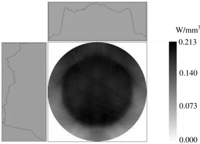
in Fig. 4. The absorbed pump flux data from the ZEMAX© analysis is then processed by
LASCAD© software. The stimulated emission cross-section of 2.38 × 10⁻¹⁹ cm-1, the
fluorescence life time of 220 s [14] and a typical scattering loss of 0.002 cm-1 for the
0.1 at% Cr: 1.0 at% Nd:YAG medium are adopted in LASCAD© analysis. A
concave-concave stable laser resonator of 300 mm length, an averaged solar pump wavelength of
560 nm [13] are used in the LASCAD© analysis. Output couplers of different
reflectivity, ranging from 85% to 99%, are tested individually to maximize the
multimode laser power. According to different resonant cavity parameters, various input
solar power/output laser power characteristics are numerically analyzed. For example,
the maximum solar laser power of 34.0 W can be achieved by adopting the 98% output
coupler with -2 m radius of curvature (RoC) in LASCAD© analysis.
Fig. 4
At high average laser power, even a nearly uniform gain distribution in a
water-cooled laser rod, as given in Fig.4, has been shown to induce a non-parabolic heat
distribution as a result of thetemperature dependence of the thermal conductivity. This
results in a radially dependent refractive power of the thermal lens, which has a
maximum along the rod axis [16]. Nevertheless, comparing to other end-pumping
schemes, the laser beam divergence of our side-pumped Cr:Nd:YAG ceramic laser is
found to be significantly reduced in LASCAD© analysis, due principally to the uniform
absorbed pump distributions shown both in Fig.2 and Fig. 4.
3. Experimental results of the side-pumped Cr:Nd:YAG ceramic solar laser
The 7 mm diameter, 30 mm length 0.1 at% Cr: 1.0 at% Nd:YAG ceramic rod is
supplied by Konoshima Chemical Co. Ltd. Japan. The optical resonator with 300 mm 1
length is comprised of two opposing concave-concave mirrors at right angles to the
optical axis of the rod, as shown in Fig.1. The rear mirror is high reflection coated (HR,
99.98%), while the output mirror is partial reflection coated (PR, 98%). Output mirrors
with RoC varying between -0.5 m and -5 m are used to test the solar laser performances.
The -2 m RoC output couplers offer the best solution. Four -2 m RoC output mirrors
with 90%, 94%, 98% and 99% reflectivity are therefore chosen to study the solar input /
laser output performances. Fig.5. shows the laser output power as a function of the input
solar power at the focus.
Fig.5
We define the slope efficiency at the focus as
focus, since only the solar power at thefocus of the parabolic mirror is considered in calculation.
laser is then defined as thelaser slope efficiency when the combined reflection losses of the heliostat-parabolic
mirror system are taken into account. Direct solar irradiance is measured simultaneously
during lasing with a Kipp & Zonen CH1 pyrheliometer on a Kipp & Zonen 2AP solar
tracker. It varies between 930 and 1030 W/m2 during the period of measurement in July,
2012. Laser output power is detected by a Molectron PowerMax 500D with less than 3%
measurement uncertainty. Two sliding doors and a shutter with motorized blades are
used to regulate the incoming solar power from the heliostat. To achieve the maximum
laser power, the shutter is totally removed. The maximum laser output power of 33.6 W
is measured for -2.0 m RoC output coupler with 98% reflectivity. The slope efficiency
of
focus= 2.6% is finally determined.A linear fiber-optic array for measuring the one-dimensional laser beam intensity
distribution in the near field is placed 5 mm away from the output coupler along the
optical axis of the laser rod [8, 10]. The 32 mm width, 128 optical fibers linear array is
used to collect and transmit laser light to a Fairchild CCD 153A 512-element linear
image sensor via a neutral density attenuator. This fiber-optic device has 0.25 mm core
pitch resolution, so less than 2% laser beam diameter measurement error is found. This
flexible fiber optic bundle has 2 m length. Outdoor solar laser beam diameter
measurement is hence facilitated. 1
For far field laser beam profile measurement, a 10” x 10” industrial standard laser
alignment thermal sensitive paper ZAP-IT@ is positioned 10 m away from the output
coupler. Assuming 3 mm reading error in the thermal sensitive paper, less than 2%
laser beam diameter measurement error is ensured.
The laser beam divergence θis found by adopting the Eq. (1):
(1)
Where ϕ1 = 7.0 mm and ϕ2 = 150 mm are the measured laser beam diameters at 1/e2
width, 5 mm and 10 m away from the output mirror respectively and L is the distance
between these two points.
M2 factor is then calculated as:
(2)
where = 0.015º is the divergence of diffraction-limited Gaussian beam for
=1.064 µm and ω0 =1280 µm, as calculated by LASCAD© laser beam propagation
method for the 7 mm diameter rod. For -2 m RoC output coupler, Mx2 = 27.5 ± 3% and
My2 = 28.3 ± 3% are experimentally determined, indicating a near symmetric beam
profile. Figure of merit B of 0.44 × 10⁻¹ W is finally calculated. Even though this value
is 6.5 times lower than our previous record of 2.9 × 10⁻¹ W [10], it is still 6.7 times
higher than that of the most recent end-pumped solar laser [9].
4. Comparison of the laser performances of both Cr:Nd:YAG ceramic and Nd:YAG single-crystal rod
The light guide dimensions, the laser rod diameters and the cavity profiles have already
been optimized by ZEMAX© and LASCAD© numerical analysis software. For
maximizing individually the laser output power from each laser medium, the 7 mm
diameter Cr:Nd:YAG ceramic rod is pumped by the compound V-shaped cavity in 2012
and the 4 mm diameter Nd:YAG single-crystal rod by the modified 2D/CPC cavity in 1
2011[10]. The fused silica light-guide with 16 mm × 22 mm cross-section is used for
pumping the 7 mm diameter Cr:Nd:YAG ceramic rod. This light guide is only slightly
thicker than the 14 mm × 22 mm cross-section light guide used for side pumping the 4
mm diameter Nd:YAG single-crystal rod. Both light guides have 140 mm length and
are manufactured from same fused silica material. The cooling water is kept also at
nearly the same working temperature of 20 ºC ± 2 ºC. From Fig.5, the following
conclusions can be drawn:
1. In comparison to our last year´s results with the 4 mm diameter Nd:YAG
single-crystal rod, as given by the lower dashed line in Fig. 5, there exists a general
improvement in laser powers with the 7 mm diameter Cr:Nd:YAG ceramic rod. For the
98% reflectivity, -2 m RoC output coupler, for example, there is 132% laser power
enhancement, as given by the upper solid line in Fig. 5. There exists also 118%
improvement in slope efficiency at the focus, from 2.2% for the single-crystal rod to 2.6%
for the ceramic rod.
2. There is no reduction in threshold power due to the use of the 7 mm diameter
ceramic rod. It is not easy to initiate solar laser operation with less than 390 W solar
powers at the focus.
For the 0.1 at% Cr: 1.0 at% Nd: YAG ceramic rod, a typical 0.002 cm-1 scattering
loss is assumed in the LASCAD© analysis. Does this ceramic rod really have such a low
scattering loss, or contrarily, it should have a much higher loss of 0.004 cm-1, as
measured in Ref. [9] ? Let us here deduce the scattering loss of the ceramic rod of our
laser system by using the same equation as given in Ref. [9]. The laser output power can
be expressed in terms of input power and measurable quantities as listed below:
P
out=
(2)
In this equation, IS the saturation gain, the cross-section area of the laser rod, R the
reflectivity of output coupler, the scattering coefficient of laser material and l the
length of laser medium. The conversion factor η can be expressed as η = ηAηQηSηB
where ηA, ηQ, ηS and ηB are the absorption efficiency, the quantum efficiency, the Stoke
factor and the beam overlap efficiency, respectively. 2lα expresses the two-way loss in
the resonator. At the same input solar radiation and resonator configuration, conversion 1
factor η is a constant value if we change only the reflectivity of output coupler. Now we
examine Eq. (2) with three variables: conversion factor η, scattering coefficient α,
saturation gain Is. These variables could be determined with three simultaneous
equations by changing the reflectivity of output couplers three times. Substituting
measured solar input powers and laser output powers, as given in Fig.5, with reflectivity
of output couplers of 94%, 98% and 99% into Eq. (2), we then get the determined
variables. The scattering loss of only 0.0018 cm-1 is finally found by our analysis. The
calculated ISvalue of 2.38 kW/cm2 also lies between the two published values [9, 17]. In
conclusion, the scattering loss of the 0.1 at% Cr 1.0 at% Nd:YAG ceramic rod is less
than 0.002 cm-1. It is not responsible for the low efficiency of the ceramic
solar-pumped lasers. By inserting the conversion factor of = 2.27% into Eq. 2, we obtain a
simple expression for laser slope efficiency:
laser =
(3)
If, for example, the laser resonator has the following parameters: R = 0.98, l = 3 cm,
cm-1 and = 2.27%, then the laser slope efficiency
laser= 1.49% iscalculated. If only 59% combined reflectivity from both the heliostat and the parabolic
mirror is taken into account, then the slope efficiency from the focus
focus = 2.53% canfinally be calculated, which matches well the experimental value of 2.6% in Fig. 5.
Since there is only less than 16% spectral overlap between the solar emission
spectrum and Nd:YAG absorption spectrum, the absorbed solar pump power is limited.
The compact CPC cavity is used to achieve efficient pumping along the 4 mm diameter
Nd:YAG rod. ZEMAX© and LASCAD© numerical analysis has also indicated the
effectiveness of the CPC scheme in attaining the maximum laser output power from the
Nd:YAG rod. Since the overlap between the solar emission spectrum and Cr:Nd:YAG
absorption spectrum can theoretically reach 40%, there are more absorbed solar pump
power available, large diameter ceramic rod can then be used to achieve more laser
output power. The compound cavity is adopted to pump the 7 mm diameter Cr:Nd:YAG
ceramic rod. The rod diameter is also optimized by both ZEMAX© and LASCAD©
analysis. The compound V-shaped pump cavity ensures the nearly top-hat absorbed 1
pumped flux distribution, as shown in Fig.4, which drastically reduces the laser beam
divergence, when compared to other end-pumped configurations.
The heat load of the 7 mm diameter Cr:Nd:YAG ceramic rod within the compound
cavity is also lower than that of the 4 mm diameter single-crystal Nd:YAG rod within
the CPC cavity. On the one hand, the Cr:Nd:YAG rod provides enhanced laser output
performance within the large compound cavity, on the other hand, the Nd:YAG rod
produce also its maximum laser output power within the compact CPC cavity, so the
comparison between the ceramic and single-crystal laser rods are made within different
pumping cavities, where the advantages of each laser rod, and therefore the laser output
performances can be fully exploited.
Side-pumping configuration provides the best heat load distribution along the rod
and the temperature dependent reduction of the 1064 nm stimulated emission
cross-section of Cr:Nd:YAG ceramic crystal [14] is not as significant as the case of other
end-pumped configurations. For this reason, there exists a general enhancement of solar
laser power by side-pumping the Cr:Nd:YAG ceramic rod. Highly intense solar
end-pumping will inevitably raise the thermal load of the ceramic rod, creating hot pump
spots along the rod, the stimulated cross-section value of Cr:Nd:YAG ceramic rod will
be reduced significantly. This, in our opinion, is the main reason of the relatively low
laser efficiency of Cr:Nd:YAG ceramics rod in high solar power end-pumping
configuration. The UV solarization effects and the IR heating can also severely
influence the laser performance of the ceramics.
5. Conclusions
High power and high efficiency solar-pumped lasers have a large potential for many
interesting applications. The radiation coupling and homogenization capacity of the
fused silica light guide is combined with the light coupling properties of the compound
V-shaped cavity to provide the efficient side-pumping tothe 7 mm diameter 0.1 at% Cr:
1.0 at% Nd:YAG ceramic rod. The introduction of the rectangular cross-section light
guide has also ensured a more stable laser emission than other pumping schemes. There
exists a general improvement of about 132% in output laser power. 2.6% slope
efficiency at the focus is also reached. The laser beam brightness figure of merit is, on 1
the one hand, more than 6 times less than that by the 4 mm diameter Nd:YAG
single-crystal rodand, on the other hand, still 6.7 times higher than that of the most recent
end-pumped solar laser [9]. The ceramic rod has also the scattering loss of only 0.0018 cm-1,
as deduced from the output laser powers by different output coupling ratios. The
non-uniform heat load problem along the laser rod is considered as the key factor affecting
the ceramic output performances of solar-pumped lasers.
Acknowledgments
This research project (PTDC/FIS/103599/2008) was funded by the Science and Technology
Foundation of Portuguese Ministry of Science, Technology and Higher Education (FCT-MCTES).
Financial support by the Access to Research Infrastructures activity in the 7th Framework
Program of the EU (SFERA Grant Agreement n. 228296) is gratefully acknowledged. We
would like to express our thanks to Dr. Takashi Ito from Baikowski Japan Co. Ltd. for the
helpful discussions about the scattering properties of the 0.1% Cr: 1.0 % Nd:YAG ceramic rod. 1
References
1. D. Graham-Rowe, Nat. Photonics 4, 64 (2010).
2. T. Yabe, T. Ohkubo, S. Uchida, K. Yoshida, M. Nakatsuka, T. Funatsu, A. Mabuti,
A. Oyama, K. Nakagawa, T. Oishi, K. Daito, B. Behgol, Y. Nakayama, M. Yoshida,
S. Motokoshi, Y. Sato, C. Baasandash, Appl. Phys. Lett. 90 261120 (2007).
3. C.W. Young, Appl. Opt. 5, 993 (1966).
4. H. Arashi, Y. Oka, N. Sasahara, A. Kaimai, M. Ishigame, Jpn. J. Appl. Phys. 23,
1051 (1984).
5. M. Weksler and J. Shwartz, IEEE J. Quantum Electron. 24, 1222 (1988).
6. V. Krupkin, J.A. Kagan, A. Yogev, Proc. SPIE 2016, 50 (1993).
7. M. Lando, J. Kagan, B. Linyekin, V. Dobrusin, Opt. Commun. 222, 371 (2003).
8. D. Liang and J. Almeida, Opt. Express 19, 26399 (2011).
9. T. H. Dinh. T. Ohkubo, T, Yabe and H. Kuboyama, Opt. Lett. 37, 2670 (2012).
10.J. Almeida, D. Liang and E. Guillot, Opt. Laser Technol. 44, 2115 (2012).
11.T. Saiki, S. Motokoshi, K. Imasaki, H. Fujita, M. Nakatsuka and C. Yamanaka, Jpn.
J. Appl. Phys. 46, 156 (2007).
12.T. Saiki, S. Motokoshi, K. Imasaki, K. Fujioka, H. Yoshida, H. Fujita, M.
Nakatsuka, and C. Yamanaka, Opt. Commun. 282, 1358 (2009).
13.H. Yagi, T. Yanagitani, H. Yoshida, M. Nakatsuka and K. Ueda, Jpn. J. Appl. Phys.
45, 133 (2006).
14.S. Zhao, A. Rapaport, J. Dong, B. Chen, P. Deng and M. Bass, Opt. Laser Technol.
38, 645 (2012).
15.ASTM Standard G159, (1998).
16.T. Brand, Opt. Lett. 20,1776 (1995).
17.M. Endo,Opt. Laser Technol. 42, 610 (2012). 1
Figure Captions
Fig.1 (a) PROMES-CNRS 2 m diameter solar concentrator with the Cr:Nd:YAG laser
resonant cavity. (b) The mechanical components of the laser resonator.
Fig.2 Double-stage light guide / compound V-shaped pump cavity for the Cr:Nd:YAG laser rod.
Fig.3 Cross-sectional view of the compound V-shaped pump cavity
Fig.4 Absorbed pump flux distribution by non-sequential ray-tracing of the 7 mm diameter
ceramic rod.
Fig.5 Cr:Nd:YAG and Nd:YAG laser output powers versus input solar power at the focus.
Fig. 1
a
Stationary parabolic
mirror HR
PR
Laser emission Focus
Laser head
Light-guide
b
PRHR
Light-guide
Laser head 1
Fig.2 Fused sílica light-guide
Uniform absorption along the rod
Uniform pump radiation
Compound V-shaped pump cavity Cooling water Concentrated solar radiation at the focus
Fig. 3 A
B C
B
A C
Compound V- shaped cavity
Cr:Nd:YAG ceramic rod
1 2 3 4
Fused silica light-guide
Water in Water out
Fig. 4
W/mm3
0.140 0 0.213 W
0.073
0.000 1
Fig.5 0
5 10 15 20 25 30 35
0 200 400 600 800 1000 1200 1400 1600 1800
L
aser
ou
p
u
t
p
ow
er
(
W)
Input solar power (W)
Nd:YAG R=90%
Nd:YAG R=94%
Nd:YAG R=98%
Cr:Nd:YAG R=90%
Cr:Nd:YAG R=94%
Cr:Nd:YAG R=98%
Cr:Nd:YAG R=99% 1
Answers to the Reviewers' comments:
Dear Reviewer 1
Many thanks for your very helpful and insightful comments
We would like to answer your comments one by one
Reviewer #1: I believe that the paper presents an interesting result. However, there are many significant misunderstanding and unclear points which should be considered before further review.
1. In Fig.5, they are comparing ceramic Cr.Nd YAG and Nd YAG crystal data but two conditions are completely different. The size is different and input source is different. I doubt this comparison and it is not scientific. In addition, "Input solar power" in horizontal axis is misleading. They should put real incident solar power on the collecting mirror. The incident solar power of two experiments is almost 4 times different.
With due respects, we think reviewer 1 has not been very careful in examining the manuscript.
In Fig.5, we are comparing ceramic Cr:Nd:YAG and Nd:YAG crystal data, the solar energy collection concentration system in PROMES-CNRS has the same size and reflectivity. The input solar irradiances are only slightly different for the two experiments in 2011 and 2012 respectively. The side-pumped Nd:YAG laser output performances, published by Optics and Laser Technology in 2012 (Ref.10), are compared to the present results.
Also from the comments of ” the incident solar power of the two experiments are almost 4 times
different”, the reviewer might have mistakenly considered our Fresnel lens end-pumped solar laser published by Optics Express in 2011(Ref. 8) for his comparison. We did not compare this end-pumped result with the present results in Fig. 5.
The collected solar power at the focus has been widely adopted as input solar power in many publications on solar-pumped lasers by Arashi (Ref 4), Weksler (Ref.5), Lando( Ref.7), Yabe ( Applied Physics Letters in 2007, Optics Letters in 2008), Liang (Ref. 8) etc, so we prefer not changing the rules during the game.
2. The authors mentioned 33.4W output but its collection efficiency is only 10W/m2 and a half of their previous result. This means the proposed scheme might have some difficulty in scaling up. This point should be discussed.
Once again, the reviewer must have mistakenly compared the 10W/m2 collection efficiency with
the 19.3 W/m2 value in Reference 8, which matches well with “a half of their previous result”.
Instead, our previous result in Ref. 10 was only 9.6W/m2 with the same PROMES-CNRS system, so
the collection efficiency is slightly enhanced by using Cr:Nd:YAG ceramic rod in 2012.
As mentioned in the manuscript, the total reflectivity of the whole solar energy collection and concentration system is only 59%. The back surface silver-coated plane mirror and parabolic mirror have more than 20 year´s service history. The collection efficiency can be largely improved by using front surface silver-coated mirrors.
Authors' Response to Reviewers' Comments
3. On page 3, they claimed the demerit of using optical fiber. However, I did not find the superiority of their system for long distant transportation of many beams. This should be essential because we can not use huge mirror for obtaining MW class laser but we need to use 1000 bundles of kW laser, because no one show the feasibility of huge laser by single optical system.
We only mention some shortcomings of optical fibers for laser power transmission. We are admirers of the renewable large-scale Mg recovery scheme proposed by Professor T. Yabe with many optical fiber bundles for kW laser. Besides, we are also interested in the multi-rods solar-pumped laser scheme at the focus of the 1MW solar furnace as proposed by Uzbekistan scientists, without optical fibers in this case.
4. As for the beam quality, I would like to know the size of the beam spot which might be used to calculate the divergence of the beam.
Far field laser beam divergence measurement was carried out again.
We have measured the 1/e2 beam spot size of about 150 mm diameter, 10 meters away from the
laser output coupler.
5. In the previous paper, they used CPC but now are using tapered cavity. I would like to know the reason of the change and how it changes the result.
The following text has been added to the revised manuscript:
Since there is only less than 16% spectral overlap between the solar emission spectrum and Nd:YAG absorption spectrum, the absorbed solar pump power is limited. The compact CPC cavity is used to achieve efficient pumping along the 4 mm diameter Nd:YAG rod. ZEMAX© and LASCAD©
numerical analysis has also indicated the effectiveness of the CPC scheme in attaining the
maximum laser output power from the Nd:YAG rod. Since the overlap between the solar emission spectrum and Cr:Nd:YAG absorption spectrum can theoretically reach 40%, there are more absorbed solar pump power available, large diameter ceramic rod can then be used to achieve more laser output power. The compound cavity is adopted to pump the 7 mm diameter Cr:Nd:YAG ceramic rod. The rod diameter is also optimized by both ZEMAX© and LASCAD© analysis. The
compound V-shaped pump cavity ensures the nearly top-hat absorbed pumped flux distribution, as shown in Fig.4, which drastically reduces the laser beam divergence, when compared to other end-pumped configurations.
6. On page 10, "the temperature dependent reduction of the 1064 nm stimulated emission ...[9]" but there is no description on stimulated emission in ref.[9]. The authors should not write a misunderstanding sentence.
Yes, the sentence has been changed to:
Side-pumping configuration provides the best heat load distribution along the rod
and the temperature dependent reduction of the 1064 nm stimulated emission cross-section
of Cr:Nd:YAG ceramic crystal [14] is not as significant as the case of end-pumped configurations.
7. The quality of ceramic laser depends on the production condition. Therefore the scattering loss changes depending on the lod. If the authors are careful enough, ref.[9] did not say the inferiority of the ceramic YAG but the ceramic they used has the high scattering coefficient. This is important because the quality changes one by one and should be improved for industrial application. Therefore they should remove the word "doubts" in abstract and introduction and so on.
Yes, the words doubt have been removed in the revised manuscript
8. Regarding the scattering coefficient, the authors mentioned on 9 that "0.004cm-1, as predicted in Ref.[9]". This is misleading because it was measured by integrated sphere but was not predicted. In addition, agreement with published value ref.[17] has no meaning because the ceramic
quality is not so stable.
Yes, "0.004cm-1, as predicted in Ref.[9]" has been changed to,
"0.004cm-1, as measured in Ref.[9]"
Dear Reviewer 2
Many thanks for your very insightful and helpful comments.
We would like to answer your concerns one by one
Reviewer #2: Solar laser attracts more attentions in research due to the potential applications in clean energy field. The authors present a comprehensive work on side-pumped CW Cr:Nd:YAG ceramic solar laser. The simulation as well as experimental results are very valuable reference for people working in this field. Nevertheless, a few issues are not clearly addressed in the manuscript.
1. Page 3, lines 39-40 describe the inner wall of the V-shaped pump cavity. What is the material of the V-shaped cavity? Why not have the pump cavity directly coated with gold or silver but bonded with a silver-coated aluminum foil?
The V-shaped cavity is bounded with silver-coated aluminum foil with 94% reflectivity by now. A gold-coated cavity will not reflect efficiently some useful solar pump power below 500 nm. Silver coating is not used due to the possible contamination with cooling water. Protected silver coating will be considered in the future version.
2. Page 6, line 44 to page 7, line 14 describe how the M2 parameter was measured, the method they used was too much simplified. Normally, the transverse beam profile at minimum five positions need to be recorded in order to fit the hyperbolic curve, so that the beam waist and far field divergence can be determined. The author only measured a very near field(5 mm) beam width and a far field beam width (1500 mm), the beam divergence calculated from these two values was not correct, therefore, the following up calculations of M2 and Figure of merit B were not reliable. In the same paragraph, the author mentioned that the diffraction-limited Gaussian beam of the same wavelength was 0.019 degree, how was this value calculated?
The following text has been added to replace the original text in the revised manuscript:
A linear fiber-optic array for measuring the one-dimensional laser beam intensity distribution in the near field is placed 5 mm away from the output coupler along the optical axis of the laser rod [8, 10]. The 32 mm width, 128 optical fibers linear array is used to collect and transmit laser light to a Fairchild CCD 153A 512-element linear image sensor via a neutral density attenuator. This fiber-optic device has 0.25 mm core pitch resolution, so less than 2% laser beam diameter measurement error is found. This flexible fiber optic bundle has 2 m length. Outdoor solar laser beam diameter measurement is hence facilitated.
For far field laser beam profile measurement, a 10” x 10” industrial standard laser alignment thermal sensitive paper ZAP-IT@ is positioned 10 m away from the output coupler. Assuming 3 mm reading error
in the thermal sensitive paper, less than 2% laser beam diameter measurement error is ensured.
The laser beam divergence θis found by adopting the Eq. (1):
(1)
10 m away from the output mirror respectively and L is the distance between these two points.
M2 factor is then calculated as:
(2)
where = 0.015º is the divergence of diffraction-limited Gaussian beam for 1.064 m and
1280 m, as calculated by LASCAD© laser beam propagation method for the 7mm diameter rod.
For -2 m RoC output coupler, Mx2 = 27.5 ± 3% and My2 = 28.3 ± 3% are experimentally determined,
indicating a near symmetric beam profile. Figure of merit B of 0.44 × 10⁻¹ W is finally calculated. Even
though this value is 6.5 times lower than our previous record of 2.9 × 10⁻¹ W [10], it is still 6.7 times
higher than that of the most recent end-pumped solar laser [9].
3. In section 4, the authors made some comparison between Nd:YAG and Cr, Nd: YAG ceramic, the experimental conditions were very different, e. g., the size of the crystal, mode volume of the resonator and pumping scheme were all different in two cases. But the authors put the results into one figure, (Fig. 5) and made comparison of the output and efficiency. So the conclusion based on this is not convincing, because other factors which could also influence the output power and efficiency were not excluded.
The following text has been added to the revised manuscript:
Since there is only less than 16% spectral overlap between the solar emission spectrum and Nd:YAG absorption spectrum, the absorbed solar pump power is limited. The compact CPC cavity is used to achieve efficient pumping along the 4 mm diameter Nd:YAG rod. ZEMAX© and LASCAD©
numerical analysis has also indicated the effectiveness of the CPC scheme in attaining the
maximum laser output power from the Nd:YAG rod. Since the overlap between the solar emission spectrum and Cr:Nd:YAG absorption spectrum can theoretically reach 40%, there are more absorbed solar pump power available, large diameter ceramic rod can then be used to achieve more laser output power. The compound cavity is adopted to pump the 7 mm diameter Cr:Nd:YAG ceramic rod. The rod diameter is also optimized by both ZEMAX© and LASCAD© analysis. The compound V-shaped pump cavity ensures the nearly top-hat absorbed pumped flux distribution, as shown in Fig.4, which drastically reduces the laser beam divergence, when compared to other end-pumped configurations.
The heat load of the 7 mm diameter Cr:Nd:YAG ceramic rod within the compound cavity is also lower than that of the 4 mm diameter single-crystal Nd:YAG rod within the CPC cavity. On the one hand, the Cr:Nd:YAG rod provides enhanced laser output performance within the large compound cavity, on the other hand, the Nd:YAG rod produce also its maximum laser output power within the compact CPC cavity, so the comparison between the ceramic and single-crystal laser rods are made within different pumping cavities, where the advantages of each laser rod, and therefore the laser output performances can be fully exploited.
4. Page 10, line 2, the scattering loss of 0.018 cm-1, one zero was missing, the correct value should be 0.0018 cm-1.