A Rigid 3D registration framework of
women body RGB-D images
António Bastos Pintor
Mestrado Integrado em Engenharia Eletrotécnica e de Computadores Supervisor: Hélder P. Oliveira
Co-Supervisor: João P. Monteiro
c
Breast cancer is one of the most aggressive diseases, affecting thousands of women every year. Usually, this kind of patients require invasive treatments, such as surgery and radiation therapy, leading to undesired physical and psychological secondary effects. At an aesthetic level, there is a demand for solutions that help processing clinic evaluations before and after the procedures, since the commonly used subjective approach is based on photography. This approach may lead to non-optimal decisions and consequently unpleasant results. For this reason, 3D body model reconstruction has been shown as a practical solution in order to facilitate the doctor’s work on observing a patient torso. The existent equipments in the market, used for 3D modeling, exhibit high-costs and normally require special knowledge behind them, making the task of applying them in a regular basis for physicians, a very complex job. Over the last 6 years, since the release of the Microsoft Kinect, there has been a growth of studies concerning low-cost RGB-D cameras. Because of this, developers have seen the opportunity to implement inexpensive and simpler so-lutions for 3D modeling in order to use them in a myriad of applications, specially in medicine. The creation of 3D models from human bodies demands algorithms to get minimal errors in the registration of the point clouds. These errors are a recurring problem, due to the non-rigidity of the human body that is captured during the acquisition process.
This thesis relies on improving and automatizing the framework that has been developed for the project PICTURE from the VCMI group of INESC-TEC, with the purpose of creating an inexpensive and easy to use 3D model system, for medical analysis on breast cancer patients, without any special knowledge. This work proposes a few improvements for the given framework, such as: automatic body pose selection, automatic segmentation process of rigid body parts, 3D data processing for noise reduction and a study of rigid registration methods for multiple clouds points is done.
The results have shown some optimistic improvements from the previous framework, where the reconstruction of the patient’s 3D models with data from low-cost RGB-D cameras were achieved with low distortion errors in comparison with models from an high-end 3D modeling System such as the 3dMD. Additionally the framework automation was accomplished for the se-lection of the patient’s pose and the extraction of rigid body parts.
Keywords: 3D Modeling and Reconstruction; Rigid Registration; Low-cost cameras; RGB-D sensors; Breast Cancer.
O cancro da mama é das doenças mais agressivas que afeta milhares de mulheres todos os anos. Geralmente, este tipo de doente necessita de tratamentos agressivos, como cirurgia e radioterapia levando a efeitos secundários indesejáveis tanto físicos como psicológicos. A nível estético existe uma procura recorrente de soluções que ajudem a processar avaliações clínicas, antes e depois, de procedimentos comuns como abordagem de avaliação subjetiva baseada em fotografia. Esta abor-dagem pode conduzir a decisões menos exatas e consequentemente a resultados desagradáveis. Por esta razão o modelação 3D para reconstrução do corpo humano tem sido apresentada como uma solução prática, que facilita o trabalho dos médicos durante a observação do torso da paciente. Os equipamentos existentes no mercado para modelação 3D, têm custos elevados e, normalmente, exigem conhecimentos prévios sobre estes. Tornando a sua aplicação regular uma tarefa complexa para o médico. Nos últimos 6 anos, desde o lançamento do Microsoft Kinect, houve um aumento dos estudos sobre câmaras RGB-D de baixo custo. Devido a isto, investigadores têm visto a opor-tunidade para implementar soluções menos dispendiosas e mais simples em modelação 3D para as usa em inúmeras aplicações, tal como na medicina. A criação de modelos 3D do corpo humano exige algoritmos para minimizar a obtenção de erros no registo das nuvens de pontos. Estes erros são um problema recorrente devido à falta de rigidez do corpo humano que são observados durante o processo de aquisição.
Esta tese assente na melhoria e automatização de uma ferramenta que tem sido desenvolvida para o projeto PICTURE do grupo VCMI, do INESC-TEC, com o objetivo de criar um sistema de modelação reconstrução 3D para a análise médica de cancro da mama de pacientes sem neces-sidade de conhecimentos adicionais. Este trabalho propõe alguns melhoramentos da ferramenta desenvolvida como: seleção automática da posição do corpo, processo automático de segmentação das partes rígidas do corpo, processamento de dados 3D para redução do ruído e um estudo sobre métodos de registo rígido de múltiplas nuvens de pontos.
Os resultados mostraram alguns melhoramentos em comparação com a ferramenta anterior, onde a reconstrução dos modelos 3D das pacientes, a partir de dados adquiridos das câmaras RGB-D de baixo custo, apresentam erros baixos de distorção, em comparação com modelos de uma sistema topo como o 3dMD. Adicionalmente a automatização da ferramenta foi conseguida na seleção da posição do paciente e a extração de partes rígidas do corpo.
Palavras-chave: Modelação e reconstrução 3D; Registo Rígido; Câmeras de baixo-custo; Sen-sores RGB-D; Cancro da mama.
Ao longo destes cinco anos de curso cruzei-me com pessoas espectaculares que contribuiram para o desenvolvimento das minhas competências e para uma vida académica mais agradável. Obrigado Miguel, Hugo F., André C., Ricardo, Isabel, Júnio, Francisco, Vilhena, Rita, Diogo, Rafa, Zé Pedro, André R., Hugo S. e Álvaro, agradeço por todas as experências que partilhamos.
Quero agradecer a todo o grupo do VCMI pela amizade, pela demonstração do grande espirito de grupo que possuem e por estarem sempre prontos para ajudar. Obrigado Ricardo, João T., Pedro, Kelwin, Eduardo, Ana, Hooshiar e aos meus orientadores João Monteiro e Hélder Oliveira. Por fim, para a minha família, não existe maneira de agradecer o suficiente por todo o apoio que me deram. Ninguém me conhece melhor que os meus pais, irmãos e avós e desde que comecei a estudar eles nunca duvidaram das minhas capacidades. Graças a isto, não custou tanto chegar até aqui.
Desejo dedicar este meu trabalho aos meus pais. Ao meu pai, pois sem ele nunca iría para engenharia pelo apoio incondicional que demonstrou desde sempre. Fez-me ver o mundo de uma forma diferente e ensinou-me importantes lições de vida. À minha mãe, agradeço por todo o seu esforço por me proporcionar uma vida feliz e tornar-me naquilo que sou hoje.
A todos o meu Muito Obrigado!
António Pintor
Abraham Lincoln
Abstract i Resumo iii 1 Introduction 1 1.1 Background . . . 1 1.2 Motivation . . . 2 1.3 Objectives . . . 2 1.4 Contributions . . . 2 1.5 Document Structure . . . 3 2 Literature Revision 5 2.1 3D imaging techniques . . . 5 2.1.1 Structured light . . . 6 2.1.2 Time of flight . . . 9 2.1.3 Stereo Vision . . . 13 2.1.4 Summary . . . 16
2.2 3D modeling applications with Microsoft Kinect . . . 17
2.3 Rigid Registration . . . 21
2.3.1 Coarse Registration Methods . . . 22
2.3.2 Fine Registration Methods . . . 22
2.4 Human Body Parts and Pose Selection and Segmentation from RGB-D sensors . 26 2.5 Depth maps Filters . . . 29
2.5.1 Bilateral Filters . . . 29
2.5.2 Outlier Remover Filters . . . 29
2.6 3D Model Reconstructing tools available on the market . . . 30
2.6.1 Crisalix 3D . . . 30 2.6.2 Vectra XT . . . 31 2.6.3 3dMD . . . 32 2.6.4 Axis Three . . . 32 2.7 Summary . . . 33 3 Previous Work 35 4 3D Model Reconstruction framework for Breast Cancer Patients 39 4.1 Acquisition challenges and conditions . . . 40
4.1.1 Microsoft Kinnect depth camera noise . . . 40
4.1.2 Acquisition Protocol . . . 41
4.1.3 Diversity of patients characteristics . . . 41 ix
x CONTENTS
4.2 Pose Selection Algorithm . . . 41
4.2.1 Segmentation using K-means quantization . . . 42
4.2.2 Closest Region Analysis . . . 44
4.2.3 Lateral Poses . . . 44
4.3 Body Part Segmentation . . . 46
4.3.1 Segment of Point Cloud for registration Frontal rPCF . . . 48
4.3.2 Segment of Point Cloud for registration Left rPCLand Right rPCR . . . . 54
4.3.3 Segment of whole Point Cloud Frontal wPCF . . . 54
4.3.4 Segment of whole Point Cloud Left wPCLand Right wPCR . . . 55
4.4 3D Data Generation for each View . . . 57
4.4.1 Preliminary Processing . . . 58
4.4.2 Point Cloud Generation . . . 60
4.4.3 Outlier Removal Filter . . . 60
4.4.4 Summary . . . 61
4.5 Rigid Registration . . . 62
4.6 Final Summary . . . 65
5 Results and Discussion 67 5.1 Pose Selection . . . 67
5.2 Body Part Segmentation . . . 68
5.3 Rigid Registration and Filtering . . . 69
5.4 Color Correction . . . 74
5.5 Conclusions . . . 74
6 Conclusions 77 6.1 Future Work . . . 78
A Acquisition Protocol 79 A.1 PICTURE – IMAGE ACQUISITION PROTOCOL MICROSOFT KINECT – 3DMK . . . 80
B Full Results 81 B.1 Pose Selection . . . 82
B.2 Body Segmentation . . . 84
B.3 Rigid Registration and Filtering . . . 90
B.3.1 Times of execution . . . 90
B.3.2 Mean Distance Error from 3dMD Model to Microsoft Kinect Model . . . 91
B.3.3 Mean Distance Error from Microsoft Kinect Model to 3dMD Model . . . 92
B.3.4 Hausdorff distance from 3dMD Model to Microsoft Kinect Model . . . . 93
2.1 Structured light principle, with vertical slits projection pattern example. . . 6
2.2 Microsoft Kinect hardware . . . 7
2.3 Orbbec Astra . . . 8
2.4 Intel RealSense R200 . . . 9
2.5 Time of flight principle . . . 10
2.6 Kinect second generation . . . 11
2.7 Softkinectic DepthSense 325 . . . 12
2.8 PMD[vision] CamCube 2.0 . . . 12
2.9 Simplified Stereo Vision System . . . 13
2.10 ZED Stereo Camera . . . 14
2.11 DUO MLX . . . 15
2.12 Ensenso N10 Stereo 3D camera from IDS . . . 15
2.13 The user rotates an object in front of a fixed Microsoft Kinect to allow a 360oview 3D reconstruction and printout the outcome 3D model . . . 18
2.14 After scanning an entire scene including the object of interest, the 3D reconstruc-tion shows the surface normals and textures mapped model. Allowing the system to monitor in real-time changes and for example color yellow the reconstruction of the segmented object that has changed position . . . 19
2.15 Virtual sphere composited onto texture mapped 3D model and calibrated live Mi-crosoft Kinect. Real-time 3D model used to handle precise occlusions of virtual by complex physical geometries . . . 19
2.16 An overview of the Weiss method proposal. (2a) Four views of the body in dif-ferent poses are captured from a single Microsoft Kinect. (2b) 3D point cloud and segmented 3D point cloud with ground plane for four frames (one shown). (2c) Recovered pose and shape (4 frames). (2d) Recovered shape in new pose. . . 19
2.17 This Figure represents the reference model and the target model. A transform is needed to be applied to make sure that these sets can be gathered in the same coordinate plane and coincident after a few iterations of the algorithm . . . 20
2.18 Environment of the experiment, where six depth cameras were placed around the user . . . 20
2.19 This Figure shows progression from two partial 3D views without any correspon-dence, that were aligned by initial feature corresponcorrespon-dence, resulting after a few iterations a final registration between the two . . . 21
2.20 An example of a failure case of registration with two views resulting in a defective registration because of the variation position of the body . . . 21
xii LIST OF FIGURES
2.21 Experimental results from Zexiao Xie paper with a comparison of two sectional point clouds from a cat toy before and after registration using different approaches: (a) before registration; (b) after registration using proposed method; (c) ICP ap-proach; (d) Chen’s apap-proach; (e) proposed method with OAPC and (f) proposed
method with OCC. . . 25
2.22 This Figure illustrates the proposed 3D object model method, going trough the steps of: (a) input meshes, (b) shape growing, (c) Multi-view Registration and (d) final result of the 3D models . . . 26
2.23 This Figure illustrates an overview of this approach by Shotton, with a single input depth image, a per-pixel body part distribution is done (colors refer the part labels at each pixel and corresponding joint proposals). This approach tries to estimate proposals for the locations of body joints in 3D space, even for multiple users. . . 27
2.24 This Figure illustrates the process of estimating the pose from a single depth image using an arbitray skeleton. With a depth image as input (top left) and a parameter-izable skeleton (top right), the algorithm will set of the parameters in order to get a skeleton which better fits with the data. . . 28
2.25 This Figure illustrates the proposed method: From a the silhoutte (a), they infer 2D human pose (b) using the models of shape (c). The mixture models of probabilistic shape templates for each limb are learnt with the depth images from the Kinect by deducing the segmentation of the limbs from the silhouette. . . 28
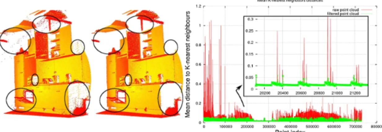
2.26 Left: raw scan; middle: scan after applying outlier removal; right: mean distances to k = 30 neighbors before and after removal. . . 30
2.27 Crisalix 3D application . . . 31
2.28 Vectra XT . . . 31
2.29 3dMDtorso System . . . 32
2.30 Axis Three system . . . 33
3.5 High-level block-diagram of the framework. . . 38
4.1 Main steps of the framework for improvement . . . 39
4.2 Cross section of the breast of an adult, female human . . . 42
4.3 Three main poses to select, (a) Left pose view (b) Frontal pose view (c) Right pose view. (d) (e) and (f) exemplar cases from the PICTURE dataset of the aforemen-tioned poses. . . 42
4.4 An high-level diagram block of the pose selection algorithm. . . 43
4.5 Background Removal. a) Examples of input normalized depth maps; b) normal-ized depth maps after applying otsu threshold and background removed. . . 43
4.6 Closest Region Segmentation a) Results after applying the K-means Clustering method for segmentation, with different colors for labeling different regions; b) The closest region is segmented and isolated to measurement its area. . . 44
4.7 Area Measurements, of the nearest region for every frame in the sequence, rep-resented by the blue line; Area measurements after smoothing, drawn by the red line; Orange line tracing the Mean area value; Purple line indicating the selected frame for frontal pose. . . 45
4.8 Centroid of two selected lateral views with the orange line indicated horizontal coordinate. (a) and (b) are right and left, respectively. . . 46
4.9 Body segmentation approach: a) Torso segmentation to be applied in every pose rPCvfor rigid registration, b) Segmentation for the wPCF pose, c) Vertical cut for wPCR, d) Vertical cut for wPCL. . . 47
4.10 Body segmentation pipeline. . . 48
4.11 Torso segmentation defined with lines limits TL- top limit and BT- bottom limit. . 48
4.12 Depth map horizontal projection. . . 49
4.13 Depth map Normalized with the horizontal projection from Figure4.12with ver-tical orientation and overlapped in blue. . . 49
4.14 Depth map with Top limit applied and the previous calculated horizontal projec-tion overlapping the image. . . 50
4.15 a) Gradient Filter with vertical orientation; b) Binary mask with the strong edges of body with the background filtered out. . . 51
4.16 Horizontal projection from the binary mask in Figure4.15b. . . 51
4.17 Resulting image after using the computed torso’s limits. . . 52
4.18 Depth map of the torso segment with a red line representing the calculated coor-dinate x of the centroid. . . 53
4.19 Top: a) Left Half of the body after gradient filter, b) binary mask with weighted negative transitions from gradient, c) After dilating edges on the binary image; Bottom: d) Right Half of the body after gradient filter, e) binary mask with weighted positive transitions from gradient, f) After dilating edges on the binary image. . . 53
4.20 Top: a) Torso segment Depth map, b) binary mask of the identified and isolated torso edges; Bottom: c) Both arms erased from the Depth map, d) Applied the 45◦degrees oblique cut for the shoulders. . . 54
4.21 The proposed algorithm applied in the lateral views Top: a) Right pose full before, b) Right pose Segmented; Bottom: c) Left pose full before, d) Left pose Segment. 55 4.22 Top: a) Depth map input, b) binary mask of the identified and isolated torso edges; Bottom: c) Both arms erased from the Depth map, d) Applied the 45◦degrees oblique cut for the shoulders. . . 55
4.23 Patient model after registration with axis for reference in 3D space, axis X in red, axis Y in green and axis Z in blue. . . 56
4.24 Left view Point cloud before a) and after b) the vertical cut. . . 57
4.25 Right view Point cloud before a) and after b) the vertical cut. . . 57
4.26 3D data Generation pipeline. . . 58
4.27 The depth images in the (b) and (d) are the same in (a) and (c) zoomed, respec-tively. The images (a) and (b) are the input and the depth images, in (c) and (d) are results after the Bilateral Filter. . . 59
4.28 The depth images in the (b) and (d) are the same in (a) and (c) zoomed, respec-tively. The images (a) and (b) are results after the Bilateral Filter in (c) and (d) are results after the Closing Operation. . . 59
4.29 Comparative Analysis of the patient models, point distribution: (a) old framework model result without filters in preliminary processing; (b) Model results with new approach for preliminary processing. . . 61
4.30 Comparative Analysis of the patient models, filling gaps: (a) old framework model result without filters in preliminary processing; (b) Model results with new ap-proach for preliminary processing. . . 62
4.31 A high-level diagram of the registration process. . . 62
4.32 Framework Registration procedure, Top: a) Input Lateral views point clouds, b) Pre-alignment, c) Coarse alignment; Bottom: d) Fine Registration, e) Patient Com-plete Point cloud model after adding the frontal view. . . 64 5.1 The average execution time in seconds for each method in the different scenarios. 70
xiv LIST OF FIGURES
5.2 The mean euclidean distances error (in millimeters) for each method and scenario, using the direction from the 3dMD model to the Microsoft Kinect model. . . 71 5.3 The average mean euclidean distances error (in millimeters) for each method and
scenario, using the direction from the Microsoft Kinect model to the 3dMD model. 71 5.4 The average Hausdorff Distance (in millimeters) for each method and scenario,
using the direction from the 3dMD model to the Microsoft Kinect model. . . 72 5.5 The complete 3D models of 7 patients in the scenario S2 with method M5. . . 73 5.6 The 3D models with the proposed method (a),(c),(e) and (g) in comparison with
the models done with the reference method (b),(d),(f) and (h). . . 76 A.1 RGB-D image acquisition protocol using the Microsoft Kinect. . . 80
2.1 A classification of 3D imaging techniques . . . 6
2.2 3D imaging Technique Strengths and Weaknesses . . . 16
2.3 RGB-D Strengths and Weaknesses comparison table . . . 17
5.1 Pose selection Success Rate results in percentage and an average percentage dis-tance error from missed selections. . . 68
5.2 Similarity Indexes Averages and Error for each Segment Results. . . 69
5.3 Combination of conditions for each scenario. . . 70
5.4 Pose selection results for the independent dataset, showing the Success Rate re-sults in percentage and an average percentage of distance error between selected frames and the closest respective pose limits, given the footage size from the re-spective patient. . . 75
5.5 Segmentation algorithm results for the independent dataset, showing the Similarity Indexes Averages and Error for each Segment Results. . . 75
B.1 Pose Selection with each patient results. . . 82
B.2 Pose Selection with each patient results, for the independent dataset. . . 83
B.3 Segmentations Similarity Jaccard Index . . . 84
B.4 Segmentations Similarity Dice Index . . . 85
B.5 Segmentations Missing Pixels Error . . . 86
B.6 Segmentations Similarity Jaccard Index, for the independent dataset . . . 87
B.7 Segmentations Similarity Dice Index, for the independent dataset . . . 88
B.8 Segmentations Missing Pixels Error, for the independent dataset . . . 89
B.9 Times of execution for each method in scenario S1. . . 90
B.10 Times of execution for each method in scenario S2. . . 90
B.11 Times of execution for each method in scenario S3. . . 90
B.12 Times of execution for each method in scenario S4. . . 91 B.13 Mean distance error from 3dMD Model to Microsoft Kinect Model in scenario S1 91 B.14 Mean distance error from 3dMD Model to Microsoft Kinect Model in scenario S2 91 B.15 Mean distance error from 3dMD Model to Microsoft Kinect Model in scenario S3 92 B.16 Mean distance error from 3dMD Model to Microsoft Kinect Model in scenario S4 92 B.17 Mean distance error from Microsoft Kinect Model to 3dMD Model in scenario S1 92 B.18 Mean distance error from Microsoft Kinect Model to 3dMD Model in scenario S2 92 B.19 Mean distance error from Microsoft Kinect Model to 3dMD Model in scenario S3 93 B.20 Mean distance error from Microsoft Kinect Model to 3dMD Model in scenario S4 93 B.21 Hausdorff distance from 3dMD Model to Microsoft Kinect Model in scenario S1 93 B.22 Hausdorff distance from 3dMD Model to Microsoft Kinect Model in scenario S2 94 B.23 Hausdorff distance from 3dMD Model to Microsoft Kinect Model in scenario S3 94
xvi LIST OF TABLES
2D Bi-dimensional 3D Tri-dimensional
API Application Programming Interface BCCT Breast Cancer Conservative Treatment CMOS Complementary Metal-Oxide Semiconductor FPS Frames Per Second
HD High Definition
Hz Hertz
ICL Iterative Closest Line ICP Iterative Closest Point
ICT Iterative Closest Triangle patch IMF Infra-Mammary Fold
INESC-TEC INstituto de Engenharia de Sistemas e Computadores - Tecnologia e Ciência
IR Infrared
NITE Natural Interaction Technology for End-User OEM Original Equipment Manufacturer
PCA Principal Component Analysis PCL Point Cloud Library
PNG Portable Network Graphics RANSAC Random Sample Consensus RGB-D Red Green Blue and Depth SDK Software Development Kit TOF Time Of Flight
USB Universal Serial Bus VGA Video Graphics Array
Introduction
1.1
Background
In the age of technological evolution, particularly in computer vision, there has been a huge search for the development of tools for 3D modeling and reconstruction of objects and scenarios, with perspectives of great potential. In the level of applicability, we can find several areas of research such as: robotics, military, quality control, 3D printing, virtual reality, multimedia, computational animation and medicine [1].
In the world of medicine there is a constant demand for new techniques and tools, with the re-quirements of being more efficient, non expensive and with an easy applicability in many different medical specialties, going from the detection of pathologies to surgery.
Breast cancer is a disease with a large incidence on women, with a high aesthetic and psycho-logical impact. Its aggressiveness implies treatments that lead, in many cases, to surgery such as mastectomy or Breast Cancer Conservative Treatment (BCCT), in other words, the local removal of the tumor [2].
In clinical breast cancer evaluations, parameters such as aesthetic, color, geometry, volume, profile and symmetry before and after treatment or surgery, traditionally resumed to photography, imply a subjective evaluation from one or more observers.
The introduction of new technologies like 3D cameras, to create complete 3D models of the torso of the woman, have allowed to estimate and do a quantitative analysis of the characteristics of the breast, helping the doctors planning their treatments, such as surgery for the patient [3]. Clinical routine needs practical tools. Much of the equipment that exists in the market has high costs, lack of portability, a complexity in its use due to the requirement of special knowledge and an increase of expenditure of hiring personnel [4].
3D modelling is considered as a field in development. Diverse organizations have presented solutions to the production of software tools and explore new techniques. Due to these orga-nizations it is possible to obtain inexpensive 3D cameras, providing free software tools with a wide shared documentation within a community that is interested in the look for innovation in the branch of computer vision [5].
2 Introduction
1.2
Motivation
Currently, there are scenarios where a surgeon would benefit from a tool which allows to share information with the medical team and show how some parameters could affect the aesthetic out-come of the surgery. From the point of view of the patient, it would be more interesting to get a more comprehensible and illustrative way to understand the conditions of a surgery, before and after, in order to observe its impact.
The existent solutions available on the market have become expensive, require specialized per-sonnel and only operate in controlled environments. The motivation for this research arises from the need of finding solutions for the breast cancer area with the introduction of modeling tech-nologies and 3D reconstruction. Those solutions should comprise simple and low-cost systems, to be used in aesthetic evaluation and surgery planning, by any healthcare professional without requiring any extra knowledge.
Taking into account that it is intended to use a non usual equipment in health, it shows how this is a major challenge to develop algorithms that build realistic 3D models and complete from several ’views’ shot of a non-rigid object, that varies its shape in time. The human body is prone to natural involuntary movements such as breathing, leading to errors in data readings very often, making the whole process harder for these systems.
1.3
Objectives
The VCMI group from the INESC-TEC, has been looking for solutions, as part of the European research projectPICTURE[6], for the development of a framework to be integrated in 3D model reconstruction system, for breast cancer analysis and treatment, with the goal of using simple and low-cost RGB-D sensors. This sensors work by collecting data through a RGB camera, in order to get several photographs and simultaneously with a depth sensor capable of getting information on the distances from the surfaces of an object of interest. After mapping and processing all the values from the collected data, this will finally result in point clouds that will be used for the registration and generation of unique complete 3D model of a woman torso.
The main objectives of this thesis focus on improving the given framework and solve its main issues as for the automation, accuracy and efficiency, in order to make it more independent of the acquisition technology and user input.
1.4
Contributions
The main contributions that have resulted in this thesis are the following:
• Body Pose Selection - Automatize the process of selecting the main views of frontal, left and right poses;
• Segmentation of rigid body parts - Automatize the segmentation of the rigid body parts to improve the rigid registration process;
• Preliminary processing - Implement a 3D data processing module, to improve the appear-ance of the point clouds by smoothing the surface and remove outlier points which result from the noise of the acquisition data with the Microsoft Kinect;
• Rigid Registration - Improve the accuracy of the algorithm so it can handle the difficulties of non rigidity from the human body and its variability in time;
1.5
Document Structure
In addition to the introduction, this dissertation contains five more chapters. For the chapter2, it is made a bibliographic revision and an overview on related works. In the chapter3, some context about the previous work done for the project ’PICTURE’ is given, in order to explain the purpose of this thesis and where it is necessary to intervene in the framework. In chapter4, it is explained in detail the methodology followed for each step of the framework that was developed. In the following chapter5 results and discussion according with the validation. Finally, in chapter6a conclusion of this work is made.
Literature Revision
In this chapter, it is discussed the state of the art related with the purpose of the thesis. It reviews what exists today and the different approaches that can be found on 3D imaging techniques, in-cluding some examples of devices which are available on the market for consumer use. Also, a few studies on their applicability in 3D modeling and body pose selection and identification are made. Next, a review about rigid registration on point clouds is done, followed by some new techniques that have been recently proposed.
2.1
3D imaging techniques
A lot of new techniques for 3D imaging have been developed over the past few decades. Taking into account the variability and complexity of different situations, not every sensor and technique may be appropriated for every kind of application. At the moment it can be said that, for all kinds of objects and scenarios, there is no single modelling technique able to satisfy all the requirements of high geometric accuracy, portability, full automation, photo-realism, low-cost, flexibility and efficiency [7].
A good part of current sensors operate primarily in two forms. First the active form, which act by projecting controlled light onto objects followed by recording the respective reflections, which will contain the information about the shape. The second is known as the passive form, where the main point is acquiring energy from an object that is being transmitted [8]. In both forms the outcome is dependent of the surrounding environment [9].
In general 3D imaging techniques can be grouped into three types of technological methods as follows: optical triangulation, time delay and the use of monocular images. For the measurements it is possible to get them with direct techniques, where they result in range data, creating a relation with distances between the surface and the sensor. Indirect measures are obtained from techniques based on monocular images or by the usage of prior knowledge about the surfaces properties [8].
The next table2.1, from the 2009 Sansoni’s review [8], classifies the variety of non-contact and optical methods used by nowadays hardware.
6 Literature Revision
Table 2.1: A classification of 3D imaging techniques (from [8]) .
T
riangulation
T
ime
delay
Monocular Images Passi
v
e
Acti
v
e
Direct Indirect Range Surf
ace Orientation Laser triangulators X X X X Structured light X X X X Stereo vision X X X X Photogrammetry X X X X Time of Flight X X X X Interferometry X X X X Moiré fringe range contours X X X X
Shape from focusing X X X X X
Shape from shadows X X X X
Texture gradients X X X X
Shape from shading X X X X
Shape from photometry X X X X
In the next sections, it is presented an overview of three very common techniques that had a major impact in several of today’s well known 3D information acquiring equipment [10].
2.1.1 Structured light
The structured light sensors project bi-dimensional patterns of non-coherent light to the scene. As the structure of the projected pattern is known, the object depth map can be reconstructed by looking at the differences between the projected and the recorded pattern. The projected pattern is deformed by the object and can be used to describe its structure orientation or texture [11] [9].
The projection of grid patterns, dot patterns, multiple vertical slits (as on Figure2.1) of mul-ticolor projection patterns have been extensively studied. There is a wide variety of patterns and decoding algorithms. However, they share a set of common characteristics or required steps that every algorithm must follow, and can be categorized in: camera projector calibration, pattern gen-eration, projection and recovery, finding correspondences, triangulation, and surface creation [12]. Since it is considered a simple process, some low-cost sensors have arisen in the markets with high data acquisition rate and with resolution quality [13] [14]. Some of the weaknesses are found in situations with missing data due the presence of occlusions and shadows [11].
In more recent developments (mobile 3d system, broadway scanner) of structured light sys-tems, the main goal has been to increase the speed of projections into multiple patterns, in order to enable the real-time acquisition, with a special look to motion and human body acquisitions [8].
Some known examples of this technique are described as it follows.
2.1.1.1 Microsoft Kinect 1.0
In November 2010, Microsoft introduced the Microsoft Kinect for the Xbox 360 video game console. Designed to work along with a video display while tracking a player body and hand movements in 3D space, it allows the user to interact with the console [15].
Figure 2.2: Microsoft Kinect hardware1.
As Figure2.2 suggests, the Microsoft Kinect contains a RGB VGA camera, a depth sensor, an infrared (IR) light source projector, a three-axis accelerometer, a multi-array microphone (to get the direction of the audio source) and a supporting hardware which allows to send information coming from the sensor to an external device via USB. It is a low weight and small dimension sensor, with an angular field of view of 57ohorizontally and 43overtically [16].
The principle of depth imaging is structured light, where the IR projector projects an IR speckle dot pattern on the object and the IR pass filtered CMOS camera captures the reflected light. The depth is calculated (by triangulation) from the deformation of the known irregular pat-tern, caused by object distance. In other words, the amount of disparity observed, will correspond to the necessary shift in order to match the pattern captured by the IR camera with the reference
8 Literature Revision
model [11]. The depth images are provided by a frame rate around 30 Hz and have a spatial res-olution of 640 × 480 pixels with 11 bits, which provides 2048 levels of depth [17]. The range of operation is 0.8 to 3.5 meters and the average resolution is 1.31 centimeters at 0.8 meters [18].
Some of the reasons that explain why the Microsoft Kinect has reached a high level of pop-ularity within the research communities are its price, which is around 100e , and the amount of documentation available online freely [10]. It comes with a versatile Software Development Kit (SDK) by Microsoft and several open-source drivers, allowing any user to connect the device to his/her own personal computer and start developing [16]. The community has never stopped working to evolve and bring a lot of new libraries and open source drivers such as OpenNI, NITE and OpenKinect [1]. All have emerged for various kind of applications in order to create tools for scene perception and analysis with the advantage of being able to be produced in many dif-ferent programming languages like C#, C++, Visual Basic, Java, Python and ActionScript [11]. On March 2013, a new library called Kinect Fusion was released which allowed to reconstruct 3D scenes in real time just by holding in hand the device and moving across space [19].
2.1.1.2 Orbbec Astra
Figure 2.3: Orbbec Astra2.
More recently, Orbbec released the Astra camera (Figure2.3) and it claims to be a powerful and reliable standalone 3D camera. It is Optimized for long and wide range distances for scenarios including gesture control, robotics and 3D scanning. It was developed to be highly compatible with existing OpenNI applications, which is ideal for pre-existing software on the market. It also comes with the Orbbec Astra SDK software for developing along side the OpenNI framework in very known operating systems such as Windows, Linux and Android [20]. For the price of $149.99 we can get a small, light-weight device, with a depth sensor, using the structured light technique, on a resolution of 640 × 480 pixels of 16bit at the rate of 30Hz. It presents a field of view of 60o horizontally and 49.5overtically with ranges between 0.4 to 8 meters [20].
https://www.linkedin.com/company/orbbec-3d-technology-international-inc-2.1.1.3 Intel RealSense R200
Intel is very well know for their production of Original Equipment Manufacturer (OEM) products. With this in mind, Intel RealSense R200 camera (Figure2.4) is meant to be integrated into the back of a tablet or laptop display in a rear-facing topology, but also to be used in installation projects by providing toolkits for developers. It offers capabilities for applications on Scene perception, face tracking and recognition, 3D scanning objects and bodies, "Depth enabled Photo & Video" and speech recognition, with the help of a microphone. Being considered good for medium-long range indoor applications, it was developed in a variety of frameworks supporting C++, C#, Javascript, Processing, Unity and Cinder, thanks to the robust RealSense SDK [21].
Figure 2.4: Intel RealSense R2003.
This camera brings a Full HD 1080p (1920 × 1280 pixels) RGB video resolution at the rate of 30Hz, while the depth sensor is at 640 × 480 pixels for a rate of 60Hz. Since it also uses the structured light, it possesses a laser projector companion with the sensor for field of view of 90o both horizontally and vertically for ranges from 0.5 to 3.5 meters. It was released in the September of 2015 and is currently available on the market for a price of $99 [21].
2.1.2 Time of flight
This active method produces a depth image from the object’s surface information in real time [22]. The object is hit with a light signal, featured as a modulated amplitude cosine wave, with a frequency generated by the sensor’s laser pulse emitter. As seen in Figure2.5, the sensor’s receiver will detect the reflection and measure the phase difference between the emitted and received lights so we can get the depth of the object at short ranges [10] [11].
This calculations can be achieved by the formula2.1, where c is the velocity of light, d the distance travelled by it, f mod is the modulation frequency and ∆ represents the phase shift [10].
10 Literature Revision
Figure 2.5: Time of flight principle from [11].
d= c 2
∆Φ
2π f mod (2.1)
Another different approach for the time of flight (easy to find in LiDAR sensors) is to send pulses with a rapid laser at the object, such that it becomes possible to calculate the time that the pulse took to travel and get back to the sensor. For close range objects, about one meter, using time of flight gets harder because the time differences get shorter. This will require high speed timing circuitry. Although the accuracy drops sharply at close measurement ranges, it is possible to get good results with medium large ranges, from 15 to 100 meters [8].
Sensors that use this technology normally face a few problems with shiny surfaces, which will not reflect so well unless they are perpendicularly oriented to the line of sight. Some key advan-tages are found as the good acquisition rate and the performance independently to the ambient light [8].
Next, a few examples of sensors using this technique are described.
2.1.2.1 Microsoft Kinect 2.0
The second generation of the Microsoft Kinect sensor (Figure2.6) was released along with the new Xbox One console by the summer of 2014. Comparing this new camera with the first generation of Microsoft Kinect, the main difference is found in the technical part with the switch of 3D imaging technique, going from structured light to the approach of Time of flight. It promised to be more precise, since it can create a series of different output images independently of ambient light [23]. Those series can be acquired at multiple modulation frequencies, which can help eliminating the ambiguity of depth measurements [11].
Figure 2.6: Kinect second generation4.
Also a few of other technical specifications have been improved to solve some drawbacks of the first Microsoft Kinect version, such as, the low geometric quality, the poor quality from the RGB camera and problems with the structured light approach, for not being always robust enough to provide complete framed scenes. Some extracted information would come with some missing parts and very noisy [11][4]. However the new camera brings an High Definition color camera (resolution of 1920 × 1080 pixels) and a new depth camera (resolution of 512 × 424 pixels) with much better field of view 70o horizontally and 60o vertically [24][23]. The new released SDK 2.0 offers tools to track six full skeleton, including the information of the position, direction and rotation of 26 skeleton joint for each detected body, with a good accuracy at the ranges of 5 meters [25]. The external hardware interface USB 3.0 makes this device able to transmit data at the rate of 30 Hz but with a new improvement on the quality of its images [24]. Although this sensor offers a new quality standard for its price, around $150, for being so recent, there is not much research and documentation available. For that reason, researchers from the computer vision communities still prefer the original Microsoft Kinect 1.0 for their own applications.
2.1.2.2 Softkinectic DepthSense 325
This camera follows the time-of-flight technique for consumer and industrial close range appli-cations [26]. As soon as Softkinetic launched this pocket camera (Figure 2.7), it alleged that it would be the most accurate depth camera at the market. It was built to provide precise finger and hand tracking into a wide range of applications in different platforms. The depth sensor delivers real time 3D distance data in order to create depth map images with a resolution of 320 × 240 pixels from a rate of 25Hz up to 60Hz. It works in a range distance between 0.15 and 1 meter, with a field of view of 74ohorizontally and 58overtically. The noise that can be found in the data normally is less than 1.4 centimeters at 1 meter distance from the object to the sensor. The RGB camera allows to record video with a resolution of 1280 × 720 pixels with a field of view 63.2o
12 Literature Revision
Figure 2.7: Softkinectic DepthSense 3255.
horizontally and 49.3overtically. With the dual microphones also integrated it allows audio-based interaction. Although production has been discontinued, it is still available for the price of $259 [26].
2.1.2.3 PMD[vision] CamCube 2.0
CamCube 2.0 is an optical sensor created by PMD[vision], considered a high-end product at the time of its release due to its performance (Figure2.8). It presents a depth resolution of 204 × 204 pixels, in an average frame rate of 25Hz for measurement ranges between 0.3 to 7 meters and with a field of view of 40ohorizontally and 40overtically [27].
Because of the use of time-of-flight technology, the key features of this device are the follow-ing: being flexible in measurement ranges using modular light sources, multi-camera operation using different frequency channels, flexible readout with programmable region-of-interest (ROI), suitable for indoor and outdoor environments and the use of Suppression of background Illumina-tion (SBI) technology. The toolkits and API available are mainly for programming interfaces in C and MATLAB [27].
2.1.3 Stereo Vision
This method uses two or more cameras that capture the same scene simultaneously in displaced space (see Figure2.9). No special equipment or projections are needed [10].
Figure 2.9: Simplified Stereo Vision System7.
The acquired images will present a small displacement, which allows to get depth informa-tion of the scene points from that divergence. The depth values for each point are calculated by means of the triangulation with the corresponding points found within a pair of images. After the calculations are made, it is possible to reconstruct the 3D scene [10].
Stereo vision, among all the passive sensors techniques, is the one that has become more popular for applications in robotics and computer vision, where the interpretation of the scenario is more important than the quality of the data, which depends with the surface texture [28].
This technique can be found in the sensors which will be next described. 2.1.3.1 StereoLabs ZED Stereo Camera
The Zed Stereo Camera (Figure2.10) is a depth sensor based on the passive stereo vision tech-nique. It is able to produce a high resolution side-by-side video on a USB 3.0 interface containing two synchronized left and right video streams. With the use of ZED SDK, a host machine is able
6
https://upload.wikimedia.org/wikipedia/commons/thumb/9/98/PMDvision_CamCube.jpg/640px-PMDvision_CamCube.jpg
7http://www.ni.com/cms/images/devzone/tut/lrlwhxvh4348425072667506924.jpg 8https://www.stereolabs.com/img/about/zed_face.jpg
14 Literature Revision
Figure 2.10: ZED Stereo Camera8.
to process the data and compute the depth map from the side-by-side video in real-time [29]. It captures video in different quality levels, being the best at 2.2K resolution (4416 × 1242 pixels) with a frame rate of 15Hz. Despite others modes provide less resolution quality, they are able to operate at faster frame rates up to 120Hz. The Depth data provide at the resolution of the video with 32-bits depth resolution per pixel, for distances ranging between 1 to 15 meters. It uses wide angle lens with reduced distortion leading to a field of view with a maximum of 110odiagonally. This camera is targeted for Windows and Linux environments with its own SDK provided for de-velopers and compatibility with OpenCV toolbox. Although the great performance and powerful hardware, the provided SDK is limited to just capturing the depth data stream, without any further processing or high level interpretation, which means that the developers are responsible for the implementation of applications, such as tracking objects and scanning scenarios. This device was released in May 2015 and can be found at the price of $449 at StereoLabs online shop [29].
2.1.3.2 DUO3D DUO MLX
The DUO MLX is a compact depth sensor (Figure 2.11), intended for the use in research areas such as robotics, inspections, microscopy and human computer interaction. It is based in the stereo vision technique combined with high power infrared LEDs and filters allowing to precisely control lighting environment for both indoor and outdoor usage [30].
It offers a configurable stereo resolution in a set of different modes, from 752 × 480 pixels at the rate of 56Hz up to 360Hz but for a lower resolution of 320 × 120 pixels. It operates in a field of view of 170owide angle and with distance ranges between 0.3 to 2.4 meters with low distortion. This specifications work for both RGB and Depth data that is processed by the provided basic SDK for the creation of depth maps although there is no higher-level interpretation. The SDK is
Figure 2.11: DUO MLX9.
available for almost every operating system including even ARM-based systems. Since its release in May 2013, it can be bought for the price of $695 [30].
2.1.3.3 Ensenso N10 Stereo 3D camera
16 Literature Revision
Imaging Development Systems (IDS) introduced the 3D stereo camera Ensenso N10 (Figure 2.12), which works by using the stereo vision principle combined with a projected light technique. It owns two global shutter CMOS sensors and a pattern projector, which is used to project a random light pattern on the object. Through triangulation, stereo images are matched with the help of the projected patterns which presents good results even in unstructured surfaces [31] [28].
It is a very light weight compact device, compared to other sensors. Besides, it provides images with a resolution of 752 × 480 pixels and operates in a distance between 280-1400 mm, at a frame rate up to 30 Hz. The depth sensor presents a resolution around 0.1mm and 1.6mm depending of the object distance. For development, IDS provides supporting software freely, which includes MVTec HALCON interface and an object-oriented API (in C++ language) [10]. Due to these specifications, this equipment may be considered as an high-end device.
2.1.4 Summary
After this overview concerning the three most common 3D imaging techniques, a summary on the pros and cons is done, with the following simplified Table2.2.
Table 2.2: 3D imaging Technique Strengths and Weaknesses.
3D imaging Technique Strengths Weaknesses
Structured Light Pattern
- High data acquisition rate;
- Not so much computation demanding; - Devices using this technique are easy to find for a low costing price;
- Prone to interference of the light conditions;
- Missing data in correspondence with occlusions and shadows;
Time of Flight
- Good data acquisition rate; - Great accuracy ;
- Performance generally independent of ambient light;
- Average cost is higher ; - Complex build and circuitry; - Multiple reflections of the emitted laser;
Stereo Vision
- High accuracy on well defined targets; - For the acquisition equipment, only need 2 cameras and no special electromagnetic emitter and sensor receiver are required; - Depth resolution as good as the RGB cameras;
- More computation demanding; - Sparse data covering;
- Limited to well defined scenes; - Low data acquisition rate; - Equipment cost;
Concerning the objectives of this thesis on getting a relatively affordable, easy to use and portable system, by the analysis of the Table2.2it is possible to conclude that the most preferred technique would be the Structured Light pattern due to the fact that it has a good combination of strengths that the others do not have. In other words, this is a technique where it is easy to find very affordable sensors, with a high data acquisition rate and does not demand so much computational resources.
10
Within the preferred technique, it is presented a summarized analysis (see Table2.3) of the main advantages and disadvantages between the previous selected and described examples of sen-sors.
Table 2.3: RGB-D Strengths and Weaknesses comparison table.
RGB-D Sensors Strengths Weaknesses
Microsoft Kinect 1.0
- Huge amount of documation and software toolkits built within the computer vision’s community available online targeting this device; - Good frame rate for both depth and color sensors;
- Low-Cost price; - Simplicity of usage;
- Accuracy dependent on lighting conditions;
- The field of view’s angles are not the best with this camera;
- Lower depth resolution
compared with more recent sensors;
Intel RealSense R200
- Small dimensions, good for portability;
- Good frame rate at 60Hz; - Cost;
- Lack of documentation support; - Depth range distances are shorter compared with others;
- No Skeleton tracking;
Orbbec Astra
- Good pixel depth resolution at 16 bits; - Large distance ranges;
- Well made system, with a fast performance processor;
- Very few supporting toolkits; - Lack of documentation support; - Low frame rate for
the RGB camera;
It is fair to conclude that, from the available sensors in the market, the one that calls more attention would be the first generation of the Microsoft Kinect. Despite having sensors with better hardware specifications, they turn out to always be more expensive, difficult to use and generally present a lack of information with software. Besides, Microsoft was the first to release an af-fordable RGB-D with great support by the computer vision community dedicated to 3D modeling. This has encouraged developers and groups of research to build the most part of the documentation and software, that are found today and available freely.
2.2
3D modeling applications with Microsoft Kinect
As previously stated, since the release of the Microsoft Kinect sensor, several researchers have given new and different perspectives in the field of computer vision, contributing specially to 3D modeling. In this section, a few projects involving the use of Microsoft Kinect sensor for 3D body modeling will be shown.
One of the first approaches in this area was presented in 2011 by the research group Kinect Fusion from Microsoft [19]. Their project contributed with a system that would allow a user to pickup a standard Microsoft Kinect camera and move around a room in order to reconstruct a very precise 3D model of the scene, with a great quality. Basically, to obtain this, the system would continually track the 6 degrees-of-freedom from the pose of the camera and fuse with the live depth data from the camera into a single three-dimensional model. As long as the user gets
18 Literature Revision
more new views of the physical scene, more data is available and revealed to be fused into the same reconstruction model, so that in the end it gets more complete and refined. A few of the uses of KinectFusion goes for Low-cost Handheld Scanning (Figure2.13), Object segmentation through direct interaction (Figure 2.14) and Geometry-Aware Augmented Reality (Figure 2.15) [32]. For the implementation, they have designed algorithms for real-time camera tracking and surface reconstruction, working altogether for parallel execution on the Graphics Processing Unit (GPU) pipeline [32]. This pipeline consist on four main stages:
• Depth Map Conversion converts image coordinates into 3D points and normals in the coordinate space, to get a live depth map.
• Camera Tracking in this phase, the goal is to align the current oriented points with the previous frame with a rigid transformation based on the 6 degrees-of-freedom.
• Volume Integration they use volumetric surface representation instead of creating a mesh by estimating the physical surface from the conversion of the oriented point into global coordinates based on the global pose of the camera.
• Raycasting In the end, the volume is raycast to extract the views of the implicit surface. This raycasted view of the volume will represent an estimation of a synthetic depth map that can be used as a less noisy and consistent reference frame for the alignment of the frames.
Figure 2.13: The user rotates an object in front of a fixed Microsoft Kinect to allow a 360o view 3D reconstruction and printout the outcome 3D model (from [32]).
In 2011 a new method was presented by Alexander Weiss for human shape reconstruction from noisy single image from one Microsoft Kinect sensor [33]. It combines low-resolution image silhouettes with coarse range data to estimate a parametric model of the body. A SCAPE body model was used, which factors a consistent 3D body shape and poses variations [34]. With a simple method it is possible to estimate standard body measurements from the recovered SCAPE model and show how the accuracy can be nearly the same as high cost commercial body scanning systems.
Guanglin Zhang published in 2014 a new technique for human body 3D modeling with the use of a single Microsoft Kinect camera, where the models are reconstructed by using the tools
Figure 2.14: After scanning an entire scene including the object of interest, the 3D reconstruction shows the surface normals and textures mapped model. Allowing the system to monitor in real-time changes and for example color yellow the reconstruction of the segmented object that has changed position(from [32]).
Figure 2.15: Virtual sphere composited onto texture mapped 3D model and calibrated live Mi-crosoft Kinect. Real-time 3D model used to handle precise occlusions of virtual by complex physical geometries(from [32]).
Figure 2.16: An overview of the Weiss method proposal. (2a) Four views of the body in different poses are captured from a single Microsoft Kinect. (2b) 3D point cloud and segmented 3D point cloud with ground plane for four frames (one shown). (2c) Recovered pose and shape (4 frames). (2d) Recovered shape in new pose. (from [33]).
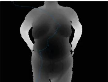
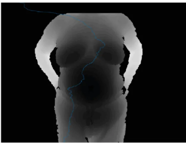
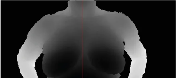
of Processing and Point Cloud Library (PCL) [35]. In order to achieve the reconstruction, it was adopted Iterative Closest Point (ICP) algorithm for registering the captured upper human body 3D point cloud data, with the standard reference human body data. The 3D data should be converted to an appropriated format so that it can be viewed in the PCL. Zhang concluded that the number of points of a human body is too much to register precisely and that may lead to a little matching error, although the use of the Kinect showed (see Figure2.17) to be enough for gathering data of the upper human body.
20 Literature Revision
Figure 2.17: This Figure represents the reference model and the target model. A transform is needed to be applied to make sure that these sets can be gathered in the same coordinate plane and coincident after a few iterations of the algorithm [35].
Another approach was presented by Zhenbao Liu [36] in 2014 with the idea of using multiple low-cost depth cameras with particular interest of using Microsoft Kinects for 3D real human reconstruction. The cameras are positioned in the form of a polygonal mesh, helping the user to enter a virtual and immersive environment. First, the system removes the static background to obtain a 3D partial view of the human, such that later every two neighboring partial views can be registered. The whole human model is registered by using all the partial views in order to obtain a single clean 3D body point cloud. The 3D mesh model is obtained from the point cloud by implementing Delaunay triangulation and Poisson surface reconstruction. This strategy has found some limitations mainly due to the involuntary motion of the users appearing in the different partial views, which leads to the lost of depth values, leading to the failure of the reconstruction process. Another observed aspect that complicates the process, is when the overlapping region between two views is almost flat, making more difficult to get an accurate registration. Because of the lack of features in the overlap, it becomes harder to find the right correspondence given two views.
Figure 2.18: Environment of the experiment, where six depth cameras were placed around the user(from [36]).
Figure 2.19: This Figure shows progression from two partial 3D views without any correspon-dence, that were aligned by initial feature corresponcorrespon-dence, resulting after a few iterations a final registration between the two (from [36]).
Figure 2.20: An example of a failure case of registration with two views resulting in a defective registration because of the variation position of the body (from [36]).
2.3
Rigid Registration
Point cloud registration is the process of overlaying two or more point clouds of the same scene taken at different times, from different viewpoints. It will align two point clouds geometrically, based on the differences between the pair due to different conditions. This process is important to achieve a complete model of the object, because of the incomplete and noisy data from just a single 3D viewpoint [37]. In medical applications, it is usual to face problems due to the non-rigid scenes causing difficulties in registration [4]. The involuntary and unpredictable movements of the object of interest and the lack of a priori knowledge about the poses and views, are a few of the challenges that researchers have been looking to overcome [38].
The 3D Registration methods can be subdivided in Coarse Registration and Fine Registration. Next a brief description for each group of methods is done, followed by some examples.
22 Literature Revision
2.3.1 Coarse Registration Methods
In coarse registration, the goal is to compute an initial estimation of the rigid motion between two point clouds using correspondences between both. In order to compute it, distances between corre-spondences are minimized. These methods can be described by: Registration strategy, Robustness, Motion estimation and kind of correspondence [39].
For the group of coarse registration, it is possible to classify on shape features or matching methods [40]. Shape features methods use neighborhood information with the goal of finding correspondences along the search for point’s characteristics. On the other hand, Matching methods focus on finding points from a pair of surfaces to be associated [39] [38].
2.3.1.1 Spin Images
This method is a 2D image characterization of a point belonging to a surface. Considering a given point, its tangent plane is computed by using the position of its neighboring points. After that, a region around the given point is considered in which two distances are computed to determine the spin image. The distance between each point to the normal vector by the tangent plane and the distance between this point to the tangent plane are defined. Finally, a table is generated with the values of the distances, where each cell contains the number of points that corresponds to a certain region. Spin images are computed in the first cloud and then, for each one, the best correspondences are sought in the second view. The transformation can be applied after finding the best correspondence [39] [41].
2.3.1.2 Principal component analysis - PCA
The idea for this method is to use the direction of the main axis of the volume given by the cloud of points to align the sequence of range images between them. In a given moment, the overlapping region will become large enough (about 50%), such that both main axes should be almost coincident and related to a rigid motion so that registration successes. In other words, the principle is to apply a single transformation which will align both axes. This method can be considered very fast but it will only be effective if there is a sufficient number of points. The most challenging detail about this method is in operation of surfaces that contain symmetries [39] [1].
2.3.2 Fine Registration Methods
In the case of fine registration, the main principle is to obtain the most accurate solution as possible. Using an initial estimation of the motion to represent all range images with respect to a reference system, the transformation matrix will then be refined by getting the best minimization in the distances between the correspondences. This is an iterative process that will try to converge to a more accurate output. Usually, these methods require a lot of processing to decide which is the closest point. The important aspects to characterize fine registration methods are: registration
principle, use of an efficient search method, robustness and minimization of the distances strategy [39].
Robustness can be seen as how well the methods deal with noise and false correspondences because of the non-overlapping regions. This is important, specially in medical images where there are always real images and the misalignments may be imminent due to the non-rigidity of objects or bodies.
2.3.2.1 Iterative Closest Point - ICP
The ICP method was presented by Besl and McKay in 1992 [42]. The main goal is to get an ac-curate result by minimizing the distance between points with correspondences, known as closest points. It is also known for being a Pair-wise registration where only a pair range image is reg-istered in every execution [39]. The algorithm can be described by the following steps, with the input of a reference point cloud followed with a second cloud:
1. Pre-processing - clean data using an outlier filter and make an inliner selection of source points from both clouds, with the options of using all points, Uniform sub-sampling, Ran-dom Sampling or Normal sampling;
2. Matching - Associate points from reference to data by finding correspondence with the use of neighbor search and/or search of features;
3. Weighting - Change importance of pairs, which depends on: distance between point-correspondences, compatibility of normals and the uncertainty of the covariance matrix;
4. Rejection - When a cloud is not a subset of the following in the sequence, some correspon-dences are outliers and those pairs must be discarded;
5. Error computation - Compute the error of each pair, which in this case is point-to-point; 6. Minimization - Find the best transformation to minimize the errors, to apply on the second
cloud, which can be the combinations of translations and rotations; 7. Go back to step 2 and repeat process until convergence.
For the Matching step, there are two possible approaches using nearest neighbor search: • Linear search, exhaustive but good for really high dimension or low number of points; • Space partitioning, K-dimensional Tree, more complex but helps to speed processing. The output of this process is going to be a transformation between the the data input and reference. A few criteria to consider convergence and stop the algorithm’s iteration can be defined as the following:
24 Literature Revision
• The transformation epsilon difference between the previous transformation (translations and rotations) and the current estimated transformation is smaller than an imposed value; • The sum of Euclidean squared errors is smaller than a defined threshold.
Iterative closest point is considered as one of the basis for 3D registration and since its disclo-sure, a lot of variants have emerged with the goals of improving the errors and the computational cost. Commonly, researchers look for alternatives to get better matching strategies or error esti-mation functions and metrics or minimization transforesti-mation algorithms [43].
2.3.2.2 Chen and Medioni Method
After Besl and McKay proposal, Chen and Medioni proposed a similar alternative to the original ICP algorithm that same year, with the standard ICP algorithm [44], with the idea of using the minimization of the distance between points and planes. The minimization function worked with the distances between point in the first point cloud with respect to tangent planes in the second. Considering a point in the first cloud, the intersection of the normal vector at that point with the second surface determines a second point at which the tangent plane is computed. At the time, they proposed a new algorithm to find intersections between lines and point clouds, which is a process that demands computational power. Although this method is more robust, with good result tests by Salvi’s review [39] against others registration methods, it has the drawback for the lack of sensibility in the presence of non-overlapping regions. Chen’s principle normally requires less iterations than the ICP approach, but due to the computational power demand, it takes more time in the in the overall process.
2.3.2.3 Iterative Closest Point Non-Linear
The Iterative Closest Point Non-linear is considered a variant of the original ICP method, with the difference of the metric used for the step of computing the error. While the original idea was the sum of squared distances between corresponding points (or point-to-plane in the Chen method), the alternative proposed was the usage of the Levenverg-Marquardt Algorithm [45] to solve non linear least-squares equations, which is seen as an optimization technique that can allow to find more generic minimization functions rather then just the sum of euclidean distances. Some results for the 3D registration were presented in the work of A. Fitzgibbon in his paper of 2003 [46]. 2.3.2.4 Generalized-ICP
Aleksandr V. Segal in 2009 released a paper [47] proposing a new idea combine the ICP point-to-point with the point-to-point-to-plane approach into a single probabilistic framework. The author claims that it can be seen as a plane-to-plane approach, since the framework models locally planar surface structures from both point clouds, which would be more robust to incorrect correspondences and making it easier to tune the maximum match distance parameter present in a big part of the ICP variants. Additionally, the proposed method allows for more expressive probabilistic models while
keeping the performance and simplicity of ICP framework and allows the addition of outlier terms, measurement noise and others techniques in order to get robustness.
2.3.2.5 Other approaches
Some studies came with another approaches instead of the ICP, such as the Iterative Closest Line (ICL) [48] which is similar to the ICP but with the difference of matching lines instead of points, from each model. It uses the Hough transformation for edge detection in order to extract lines to be used in point clouds by projection. Also in some situations it is used the Iterative closest Triangle (ICT) [49], where the search is for sets of three points to form triangles. This means that large triangles represent points that are far from each other, and for the opposite, small triangles can be easily found in curved surfaces [4].
In 2010 Zexiao Xie released a paper [50] with a proposal of a high-accuracy method for fine registration of overlapping point clouds. The algorithm is basically a variation of the Method of Chen, with the approach of establishing the original correspondences from two point clouds by adopting a dual surface fitting using a B-spline interpolation. The combined constraint uses global rigid motion in conjunction with local geometric invariant to reject unreliable correspondences, in order to estimate transformation parameters in an efficient way. This method takes in account the surface shape and geometric properties of the object, claiming to be less likely influenced by the quality of the original data sets. His experimental results (see Figure2.21) demonstrated high registration accuracy in the overlapping region and uniform error distribution.
Figure 2.21: Experimental results from [50] with a comparison of two sectional point clouds from a cat toy before and after registration using different approaches: (a) before registration; (b) after registration using proposed method; (c) ICP approach; (d) Chen’s approach; (e) proposed method with OAPC and (f) proposed method with OCC.
A more recent study published in 2014 by Y. Guo [51] proposed an algorithm for pairwise and multi-view range image registration. The first step of the algorithm extracts a set of Rotational
![Figure 2.18: Environment of the experiment, where six depth cameras were placed around the user(from [36]).](https://thumb-eu.123doks.com/thumbv2/123dok_br/18801938.925953/40.892.203.650.810.1045/figure-environment-experiment-depth-cameras-placed-user.webp)
![Figure 2.22: This Figure illustrates the proposed 3D object model method, going trough the steps of: (a) input meshes, (b) shape growing, (c) Multi-view Registration and (d) final result of the 3D models (from [51]).](https://thumb-eu.123doks.com/thumbv2/123dok_br/18801938.925953/46.892.163.682.378.561/figure-figure-illustrates-proposed-object-method-growing-registration.webp)