Proceedings of the Fifth European Conference on Underwater Acoustics, ECUA 2000 Edited by P. Chevret and M.E. Zakharia
Lyon, France, 2000
UNDERWATER ACOUSTIC COMMUNICATION USING A
“VIRTUAL” ELECTRONIC TIME-REVERSAL MIRROR APPROACH
A. Silva*, S. Jesus*, J. Gomes** and V. Barroso**
*Universidade do Algarve, UCEH, SipLab, Campus de Gambelas, 8000 Faro, Portugal email: [email protected], [email protected]
**Instituto Superior Técnico – Instituto de Sistemas e Robótica, Av. Rovisco Pais, 1049-001 Lisboa, Portugal
email: [email protected], [email protected]
This work presents a technique for reducing the intersymbol interference (ISI) in underwater coherent communications using time-reversal acoustics. The paper introduces a “virtual" time-reversal mirror (TRM) that is implemented electronically at the receiver array and simulates the kind of processing that would be done by an actual TRM during the reciprocal propagation stage. In both cases, a probe pulse sent by the transmitter/receiver located at the (physical or virtual) focal point and received at the array provides a template impulse response for undoing the effects of multipath by straightforward linear filtering. Very simple equalization algorithms may subsequently be used to decode the message.
Channel variations between transmission of the probe and the actual message lead to mismatch that can impact the coherence of TRMs, and hence degrade the focusing power of the array. Computer simulations using a normal-mode propagation model in a reallistic shallow water scenario show that, even with high uncertainty in the transmitter and receiver relative positions, the virtual mirror can strongly reduce the effects of multipath. Although a multichannel equalizer attains a lower mean-square error, the "virtual" TRM can provide comparable results under low mismatch with much smaller complexity.
1. Introduction
In practical underwater acoustical communication systems coherent modulation seems to be the most viable option for obtaining high data rates in the ocean, where the available bandwidth is inherently restricted as a result of frequency-dependent sound absorption. Effective coherent receivers usually exploit spatial diversity and use powerful multichannel equalization algorithms to attain acceptable error rates [1]. A different approach, based on time-reversal acoustics, is proposed in this paper.
Recent field experiments performed by Kuperman et al. have shown that a time-reversal mirror (TRM) may be a viable technical solution for underwater applications such as adaptive
sonar and digital communications [2]. In TRM experiments, a probe signal from a source at location A is transmitted to a source-receiver array (SRA) at location B. The spatially-sampled acoustic field at location B is then time-reversed, and retransmitted back to location A using the array of sources which are collocated with the receiving hydrophones. If the ocean environment does not change significantly during the travel-time, the time-reversed field generated by the array of sources will refocus at the source location A. The focus is both spatial and temporal, and results from a recombination of the multipath structure of the channel. Intuitively, the ocean creates a complex multipath signal at B during the first transmission, while the second transmission undoes the multipath.
Assuming that the TRM is positioned at a fixed station (FS), sound may be readily concentrated in both time and space at a autonomous underwater vehicle (AUV) location if the basic multipath-distorted constellation pulse shapes are available at the mirror [3],[4]. In the reverse direction, from AUV to FS, a different technique is needed. The approach proposed in this paper is based on the concept of a “virtual TRM”, i.e., a multichannel recombination strategy implemented at the mirror that reflects the type of processing performed by the ocean in the reciprocal propagation phase. A channel probe is sent prior to the data block, containing a single PAM signaling pulse. The distorted probe signals received at the array sensors are time-reversed and used to filter the associated data blocks, which are then added to regenerate an information-bearing PAM signal with mild intersymbol interference. Decoding of the transmitted symbols under these conditions does not require complex equalization algorithms. Note that transmission of a single-pulse probe signal is also required for the mirror to focus back at the source position, hence the proposed virtual TRM processing scheme does not necessarily imply loss of efficiency in channel use.
2. Simulation Geometry
Figure 1 depicts the simulation geometry and indicates the predicted environmental characteristics. A typical summer sound-speed profile is used, with constant speed up to 14 meters, and linearly decreasing at greater depths. A layer of gravel (density 2g/cm3, attenuation 0.6dB/λ) with uniform thickness of 6 meters is assumed between the water and a rigged bottom (density 2.4g/cm3, attenuation 0.1dB/λ). Figure 2 presents the Transmission Loss for a frequency of 10KHz.
Array 1 5 1 0 1 5 2 0 1 8 0 0 1 8 1 0 3 0 0 0 c [m/s] AUV 0 3 6 4 0 4 6 Sediment gravel Sub-bottom Water column Depth [m] R a n g e 2 k m
3. Data model
The transmitted PAM signal is represented as
∑
+ ∞ − ∞ = − = i b iT t p i a t x( ) () ( ), (1)where a(i) is the sequence of complex constellation symbols, T is the signaling interval,b
and p(t) is the baseband pulse, typically having a raised cosine-like shape. The structure of a signaling frame is depicted in figure 3. The probe signal (PS) is simply a PAM pulse p(t) whose main function is to provide a filter template for the virtual TRM, although it may also be useful for coarse frame synchronization. The distorted probe signal at the k-th hydrophone is given by ) ( ). ( ) ( ) ( ) ( ) ( 1, 1, 1, , 1k t pt g k t Y k ω Pω G k ω y = ∗ ↔ = , (2)
where g1,k(t) is the corresponding channel impulse response. The received data portion of the frame has a similar form
) ( ). ( ) ( ) ( ) ( ) ( 2, 2, 2, , 2k t xt g k t Y k ω X ω G k ω y = ∗ ↔ = , (3)
but g2,k(t) is the new channel impulse response for hydrophone k, which may differ slightly from g1,k(t)due to variations in the transmission geometry. The regenerated signal at the virtual focus is obtained by adding together all multipath-distorted data signals, filtered by their associated (complex conjugated) time-reversed probes
∑
∑
= ∗ = ∗ − ∗ ↔ = = K k k k K ki k k t y t Z Y Y y t z 1 , 2 , 1 1 , 2 , 1 ( ) ( ) ( ) ( ). ( ) ) ( ω ω ω . (4)The structure of this processor is shown in figure 4.
PS Data Signal t1 t2
Fig. 3: Signaling frame
channel 1 + Phase Conjugation P(w)1/2 P(w)1/2 1 probe signal n channel 2 + P(w)1/2 P(w)1/2 a(i) data signal n z(t) Matched Filter
Fig. 4: Virtual TRM structure
Using (2) and (3) in (4), the spectrum Z
( )
ω may be written as∑
= ∗ ∗ = K k k k G G P X Z 1 , 2 , 1 ( ). ( ) ). ( ). ( ) (ω ω ω ω ω . (5)If channel variations are negligible between the probe and data transmissions, then the sum of Green’s function products in (5) approaches a constant value for a sufficiently long and dense array that intercepts most of the acoustic energy in the water column [2]. Hence
) ( ) ( ) (ω ≈C⋅X ω P∗ ω Z , (6)
where cylindrical propagation loss, water density variations and constant terms are lumped into the term C. If X
( )
ω is a PAM signal with spectral pulse shape P(ω), then Z(ω) is alsoPAM with normalized pulse shape P
( )
ω 2. It is clear from (6) that the originally transmitted signal is not regenerated by the virtual mirror, but this is not a serious impairment in digital communication applications, where the main goal is to obtain a waveform with low ISI. If) (ω
P is selected as a root-raised-cosine pulse, then the "virtual" mirror output will be a raised cosine PAM sequence, as intended.
Assume now that G2,k
( )
ω differs from G1,k( )
ω as a result of transmitter (AUV) motion between the probe and data parts of a frame caused by currents or other disturbances. Then∑
= ∗ K k k k G G 1 , 2 ,1 (ω). (ω) may be interpreted as the field generated by a TRM at the new location
due to a source at the original position, i.e., the "virtual" time-reversed acoustic field will not be sampled exactly at the focus. Other types of variations, such as random fluctuations in the environment and relative motion during reception of the data part, are outside the scope of this work.
4. Simulation results
The effective length of PAM pulses at the virtual mirror output will be adopted as a measure of residual ISI. This length is defined as the minimum time interval, of the equivalent baseband TRM pulse energy distribution t t hτ dτ hτ dτ
2 2 ) ( / ) ( ) (
∫
∫
∞ ∞ − ∞ − = Φ , where96% of the total pulse energy is concentrated. Good agreement has been found between this quantity and other ISI measures such as the mean-square dispersion of the constellation in a symbol-rate sampled discrete sequence obtained from the TRM output.
Subsequent testes have been performed using 2-PSK modulation at 1000bps with carrier frequency 10KHz and root-raised-cosine shaping at the transmitter (25% rolloff).
Figure 5 shows the evolution of received pulse lengths as a function of range for 4 arrays with different numbers of sensors and constant length between depths 2.5m and 36.5m. It is assumed that the probe pulse is transmitted from r =2015m, z =36m, and the source is then relocated between 2000m and 2030m at the same depth before transmitting the data block. As expected, lower lengths are obtained with denser arrays at the focus (and other ranges), since they approximate the behavior of a continuous mirror with greater accuracy. The sidelobe structure in these curves agrees with simulation results presented in [3] for the variations in transmission loss (TL) around the focal point. Intuitively, this property stems from the fact that increases in TL near the focus are mainly due to destructive interference among the strongest acoustic paths, which have low propagation delay.
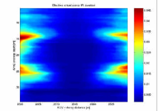
Simulations were also conducted to assess the performance of an array with 18 hydrophones spaced 0.5m apart at different depths for various degrees of mismatch in the mirror. Figure 6 depicts the variation in pulse length at the mirror output as a function of range and array depth. Since the highest pressure levels are found near the bottom (see fig. 2), these results support the conclusion in [5] that, for a given (continuous) array, best focusing performance is obtained when a maximum of acoustic energy is intercepted in the water column. Comparing figures 2 and 6 for range 2Km, it is verified that this holds even for relatively large mismatch; transmission loss maxima at depths 15m and 25m translate into longer impulse responses, while the shortest pulses at the mirror output are again obtained near the bottom.
Fig. 5: Pulse lengths as a function of array element spacing
Fig. 6: Pulse lengths as a function of array depth
All the previous results have been obtained in the absence of noise, which affects receiver performance not only by disturbing the data part of the message but, most importantly, by corrupting the probe pulse used for subsequent filtering, hence introducing long-term ISI in the mirror output. To limit the latter effect, received probes are truncated around the higher-energy region using a rectangular window whose length is determined by the a priori expected pulse temporal dispersion for the transmitter/receiver geometry. Figure 7 shows the evolution of mean-square error (MSE) at the input of the symbol slicer as a function of range mismatch for three different receiver architectures:
1. Virtual mirror with 18 evenly-spaced sensors between depths 28m and 36.5m. The mirror output is sampled at the symbol rate, using a timing offset that ensures maximum power. The resulting discrete sequence is scaled in both amplitude and phase to align the symbol constellation with the slicer decision boundaries.
2. Same virtual mirror as above, but the output is oversampled by a factor of 2 and applied to a single-channel RLS equalizer with a total of 20 coefficients.
3. Multichannel FSE of [1] operating directly on the output of four evenly-spaced hydrophones between 6.5m and 25m, oversampled by a factor of 2. A total of
76 19
4× = adaptive coefficients were used in the RLS algorithm.
The signal to noise ratio at each hydrophone is 30dB in all cases. Although the virtual TRM was proposed as a pre-processing technique to reduce the required equalizer complexity, figure 7 shows that the reduction in ISI may be large enough to allow reliable decoding by itself. The figure also confirms the graceful degradation in mirror output as the mismatch increases [4], which may be highly relevant in practice when operating under time-varying conditions. An additional MSE gain of 5dB was readily obtained using a very short equalizer. The multichannel FSE exhibits the best results, with minor MSE variations across the considered ranges. This performance is obtained with an RLS equalizer whose complexity is (76/20)2 =14.4 times greater than that of receiver 2.
5. Conclusion
This work has proposed a virtual TRM receiver architecture for coherent underwater acoustic communications. The technique relies upon transmission of a channel probe prior to
the digital message that provides a filter response for coherently combining the signals from an array of hydrophones, and hence cancel most on the intersymbol interference introduced by the channel. Robustness is ensured by the fact that no direct assumptions regarding environmental parameters are made. However, prior knowledge about the environmental is useful, since it allows the mirror hydrophones to be placed so as to maximize the focusing performance.
Experimental results have shown that reliable decoding near the focus is attainable with an equalizer whose complexity is significantly lower than that of the popular multichannel FSE, although the latter may exhibit better output MSE. Performance degradation at the mirror output due to channel mismatch between transmission of the probe and data is gradual. The resulting stability of received signals in the vicinity of the virtual focus may be important in practice, as it reduces the tracking requirements of post-processing adaptive algorithms.
Future work will address alternative techniques for limiting the impact of noise on the probe signal. Tracking strategies to detect mismatch and automatically correct the location of the virtual focus will also be studied.
Fig. 7: MSE performance for different receivers
REFERENCE
[1] M. Stojanovic, J. Catipovic, and J. Proakis, “Adaptive multichannel combining and equalization for underwater acoustic communications”, Journal of the Acoustical Society
of America, 94(3), pp. 1621-1631, 1993.
[2] W. Kuperman, William Hodgkiss, and Hee Song, “Phase Conjugation in the Ocean: Experimental Demonstration of an Acoustic Time-Reversal Mirror”, Journal of the
Acoustical Society of America, 103(1), pp. 25-40, 1998.
[3] A. Abrantes, “Examination of Time-Reversal Acoustics in Shallow Water and
Aplications to Underwater Communications”, M. Sc. Thesis, Naval Postgraduate School,
Monterey, California, 1999.
[4] J. Gomes and V. Barroso, “A Matched Field Processing Approach to Underwater Acoustic Communication”, In Proceedings of OCEANS’99, Seattle, USA, vol. 2, pp. 991-995, 1999.
[5] D. Jackson, and D. Dowling, “Phase conjugation in underwater acoustics”, Journal of