Developing Low-power Cellular IoT Solution with Narrowband IoT and Lightweight M2M
Metropolia University of Applied Sciences Bachelor of Engineering
Information Technology Bachelor’s Thesis 16 December 2019
Author Title
Number of Pages Date
Sy Hoang Mai
Developing Low-power Cellular IoT Solution with Narrowband IoT and Lightweight M2M
60 pages + 2 appendices 16 December 2019
Degree Bachelor of Engineering
Degree Programme Information Technology Professional Major Smart Systems
Instructors Keijo Länsikunnas, Senior Lecturer Toni Rosendahl, Thesis Instructor
The rise of the IoT era has witnessed the emergence of new and disruptive Low Power Wide Area technologies. One of those innovations, Narrowband Internet of Things (NB- IoT), is a new standard specified in the 3GPP project to enable a wide range of IoT cellular applications by focusing on extended coverage, high-density deployment, low energy con- sumption, and low-cost end device. Furthermore, this wireless technology is a promising replacement candidate for legacy cellular M2M systems, which will be slowly phased out by the 2G and 3G sunset.
Lightweight Machine to Machine (LwM2M) is a new device management protocol aspiring to go beyond the current de facto IoT messaging MQTT. This new framework offers a stand- ardisation in IoT device management and information reporting, thus promoting a high-level of interoperability among applications and cloud services. Furthermore, Lightweight M2M over UDP presents a significant advantage compared to MQTT over TCP for low power cel- lular devices.
This paper documents the process of developing firmware for an IoT device utilising the two technologies mentioned above, and at the same time, supplies relevant knowledge and anal- ysis on subjects encountered throughout the project execution.
The outcome of this thesis is a functional proof-of-concept low power IoT device, which is capable of delivering sensor measurements to an LwM2M server securely via NB-IoT. The thesis is going to be used as a reference design at Etteplan Embedded Finland Oy to speed up future developments.
Keywords IoT, NB-IoT, LwM2M, STM32, Mbed OS, Low power
List of Abbreviations
1 Introduction 1
2 Theoretical Background 2
2.1 Device Management System 2
2.1.1 Lightweight M2M Protocol Architecture and Functionality 3
2.1.2 Device Management in Lightweight M2M 5
2.1.3 CoAP in Lightweight M2M Service Enablement Interface 9 2.1.4 Lightweight M2M Resource Model and Information Reporting 11
2.2 Narrowband Internet of Things (NB-IoT) 15
2.2.1 Cellular IoT in Internet of Things Landscape 16
2.2.2 Narrowband Internet of Things 17
2.2.3 NB-IoT Connection States and Low Power Features 19
2.2.4 Power Saving Techniques in NB-IoT 21
2.2.5 NB-IoT Power Consumption Best Practices 26
2.3 Mbed OS 27
3 Design and Implementation 29
3.1 Project Goal and Requirements 29
3.2 System Components Selections 30
3.2.1 Main Hardware Components Selections 30
3.2.2 Software Component Selections 31
3.2.3 Guide on U-blox SARA-N211 NB-IoT Modem 32
3.3 Development Environment and Team Collaboration Workflow 33
3.4 System Design and Software Architecture 34
3.5 Software Testing 37
3.6 Optimising Power Consumption from Software Perspective 39 3.7 Challenges Encountered during Project Execution 42
4 Result and Discussion 44
4.1 Project Outcome 44
4.2 Comparison between NB-IoT with Competing Technologies 45
4.2.1 Comparison from Business Perspective 45
4.4 Security Considerations Regarding Project 49 4.5 UDP vs TCP as Transport Layer for IoT Applications 51
4.6 Future Developments 52
5 Conclusion 54
Referencess 55
Appendices
Appendix 1. NB-IoT applicable eDRX cycle length and paging time window Appendix 2. NB-IoT Active timer (T3324) and TAU timer (T3412) encoding
API Application programming interface BLE Bluetooth Low Energy
CI Continuous integration. A practice of merging all developers’ works to a shared mainline, often automated nowadays.
DTLS Datagram Transport Layer Security. A protocol providing security for data- gram-based communications.
DUT Device under test. Refers to the device that undergoes a testing procedure.
eDRX Extended/Enhanced Discontinuous Reception. This feature in NB-IoT im- plies the mechanism of extending the cycle between paging attempts.
IDE Integrated development environment. An application offering a set of com- prehensive tools for programmers to develop software.
IPSO WG “Internet Protocol for Smart Objects” Working Group. An organisation focus- ing on promoting global interoperability of IoT device based on open stand- ards.
IWDG Independent watchdog. A hardware element which resets the system if not refreshed after a determined period, often used as the last line of defence to rescue the system from unexpected software failure.
IoT Internet of Things. Generally, this term identifies anything that has a direct or indirect connection to the Internet. In this thesis, this term addresses embedded devices with such characteristics.
LPWAN Low power wide area network. A type of wireless communication technol- ogy designed for low-powered, long-range communications.
LTE Long Term Evolution. A cellular standard specified by the 3GPP project, commonly known to consumers as 4G technology.
LoRaWAN An LPWAN technology developed by Semtech based on LoRa technology.
LwM2M Lightweight machine to machine. A protocol specified by the Open Mobile Alliance for Machine to Machine communications and IoT devices manage- ment.
MCU Microcontroller unit M2M Machine to Machine
MQTT MQ Telemetry Transport. A popular standard messaging protocol for Ma- chine to Machine in IoT applications.
MTC Machine-type communication. A synonym for Machine to Machine commu- nication.
MTU Maximum transmission unit. This value specifies the maximum size of an IP packet can be transported via a medium without fragmentation.
NAT Network address translation. A method of mapping one IP address space into another by modifying the IP header, widely utilised as the way to con- serve the address space from the IPv4 exhaustion.
NB-IoT Narrowband Internet of Things. A low power wide area network technology specified by 3GPP, focusing on serving IoT applications.
OMA Open Mobile Alliance. A standards body which develops open standards for the mobile phone industry.
PAT Port Address Translation. An extension of NAT, enabling multiple devices in a local network to be mapped to a single public IP address.
PSM Power Saving Mode. In the LTE context, the term indicates the sleep mode of the UE during which it exhibits the lowest current consumption.
RTOS Real-time operating system. An operating system intended to serve appli- cations with real-time demand, widely used in embedded system projects.
TAU Tracking area update
TCP Transmission Control Protocol. A session-oriented communication model of the IP stack, providing an ordered and reliable communication scheme for Internet applications.
UART Universal Asynchronous Receiver/Transmitter. A hardware component used for asynchronous serial communication, often integrated within the microcontroller.
UDP User Datagram Protocol. A connectionless communication model of the IP protocol, mainly used by low-latency and loss-tolerating applications.
UE User equipment. In the cellular context, this term implies any device used by an end-user to communicate with the network.
URC Unsolicited Result Code. A message sent from the mobile equipment which is not an immediate result of an AT command, used for delivering an arbi- trary event (e.g. modem has received a call) or result code of an asynchro- nous operation.
WWDG Window watchdog. This component resets the system if not refreshed within a specific time window. Similar to the independent watchdog, it is used to rescue the system from an unexpected failure.
1 Introduction
The emergence of the Internet of Things (IoT) is considered to be the next revolution in data communication with a mission of forming an ecosystem in which each and every device is connected and able to make intelligent decisions. This newly emerged capabil- ity not only offers improvements to existing automation and manufacturing industries but also advances other fields such as agriculture, transportation, and healthcare by provid- ing means for optimisation in efficiency and flexibility while cutting down excess ex- penses [1]. According to an Ericsson forecast [2, p. 8], by 2024, there will be approxi- mately 22 billion IoT devices connected to the Internet. Consequently, this tremendous number of connections urges for new versatile and scalable wireless technologies that met the demand for future growth and changes in the IoT world.
Evidently, the characteristics of the connectivity technology have always played an es- sential role in deciding whether will it be adopted by the mass as commercial projects are driven by use-cases. For example, WiFi, a wireless protocol designed for low latency and high throughput communication, has become the preferred option for smart con- sumer devices thanks to its availability in virtually any modern home of the Western world. Unfortunately, this ubiquitous wireless protocol does not fit into applications where there is an appeal for low-power consumption and long radio range support along with a high degree of scalability. On the other hand, a large proportion of the IoT world is con- strained devices infrequently send out a small amount of data and sleep most of the time to conserve energy, while considering low latency as a non-critical attribute. There have been many attempts to design wireless technologies to satisfy these expectations, and one of those promising pursuits is Narrowband IoT (NB-IoT) – a recent extension of the LTE standard which seeks to provide connections for billions of IoT devices worldwide over cellular. At the moment, network operators around the world are starting to sunset their 2G networks, leaving out a great opportunity for this new technology enter the ma- chine to machine (M2M) market.
The goal of this thesis was to document, describe and explain the knowledge needed as well as the process of developing an IoT device which utilises NB-IoT and Lightweight
Machine to Machine (also known as Lightweight M2M or LwM2M) from a software de- veloper perspective. The remainder of the thesis is organised as follows: Section 2 pre- sents the theoretical knowledge of LwM2M and NB-IoT. Section 3 describes how the project was carried out with technical depth. Section 4 states the project outcome and provides additional discussions and analysis on different aspects that emerged during the implementation phase. Finally, Section 5 concludes the paper.
2 Theoretical Background
This theoretical background section provides the audience with the fundamentals of de- vice management, Lightweight M2M protocol, and Narrowband IoT to prepare a solid ground for later discussions. Reference materials comprise official Lightweight M2M specification, articles collected from journal databases such as IEEE, MDPI, and devel- opment support documents presented by U-blox since their cellular module is used in the project.
2.1 Device Management System
As the number of connected devices soars, so are the demand for organisations to man- age, configure and monitor their device fleets. Nevertheless, a device management sys- tem is not a new concept as this technique was adopted by mobile and Internet operators many years ago to supervise and provision devices. A device management framework generally offers a basic set of functionalities:
• Provision devices: concerns the bootstrapping process which setup identity and first configurations of the device.
• Configuration: allows administrators to remotely change device settings and parameters.
• Update: provides a software update delivery mechanism for deployed de- vices.
• Fault management: delivers fault report in case of a system failure, which helps maintenance to be carried out quickly and efficiently as possible to minimise loss.
These functionalities are expected to be performed securely under appropriate access right configurations and authentication scheme. A device management protocol, which defines operations between devices and its administrators, can be examined through three different aspects [3]:
• Protocol architecture: depicts how messages are packed and transported across the communication channel.
• Connection dynamics: characterises the communication paradigm be- tween server and client.
• Standardised data model: describes the data model shared between server and client to perform operations defined by the protocol.
In subsequent sections, LwM2M protocol’s characteristics, along with its features, are discussed in more details following these aforementioned criteria.
2.1.1 Lightweight M2M Protocol Architecture and Functionality
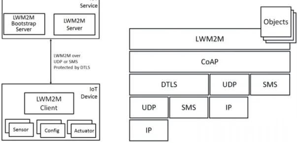
Lightweight M2M is a new device management protocol defined by Open Mobile Alliance (OMA), whose goal is to provide a holistic solution for remote management and service enablement in sensor networks and M2M environment. Figure 1 describes the architec- ture of Lightweight M2M protocol along with a simplified representation of its communi- cation model.
Figure 1. Lightweight M2M 1.0 architecture (right) and its simplified communication model (left).
Copied from Mikko Saarnivala [4, p. 5]
As illustrated in Figure 1, the LwM2M layer lies on top of Constrained Application Proto- col (CoAP), and below that are supported transport layers such as UDP, TCP, SMS, or LoRaWAN (TCP and LoRaWAN added in Revision 1.1) used for data transfer. This lay- ering approach in the protocol stack separates responsibilities within the chain, making it transparent for developers who implement the LwM2M library as well as the library users.
Lightweight M2M protocol operates in a client-server model in which the server is the LwM2M server while clients are IoT devices. As the protocol adopts RESTful operations carried out over CoAP to perform its transactions, it is sensible to make the earlier clari- fication because from CoAP perspective LwM2M server is a CoAP client and managed device is a CoAP server. On the other hand, it is also worth noting that LwM2M protocol allows a device to register to and be managed by multiple servers, though this feature may introduce challenges for implementation and operation in practice. The LwM2M specification defines an object called Access Control Object, which specifies the permis- sion each server has on a particular object or object instance within the client. For sim- plicity and conciseness purpose, the rest of this paper mostly refers LwM2M server in the singular form, assuming the management relationship consists of one server and one client. Figure 2 presents a high-level view of the data structured in a Lightweight M2M client.
Figure 2. Data representation in lightweight M2M client data structure.
The LwM2M client, or the managed IoT device in this context, exposes its data to the server through a flat tree data structure. Each node of the tree is called an object, which can be single or multi-instantiable, consists of one or many resources. Each resource can take the form of a boolean, an integer, a string, an opaque or a method (action) that
may be read, written or executed. More depth on data representation and information reporting are covered in Chapter 2.1.4.
2.1.2 Device Management in Lightweight M2M
As a quick recap from earlier, LwM2M protocol operates in a client-server model, provid- ing many IoT services including device bootstrapping as well as managing device state and collected data. An LwM2M server can serve multiple devices at the same time. On the other hand, a device can be managed by multiple servers, yet this is not a popular approach at the moment. This sub-section examines the bootstrap procedure, device management functionality and fault reporting process within the protocol.
2.1.2.1 Lightweight M2M Bootstrap Procedure
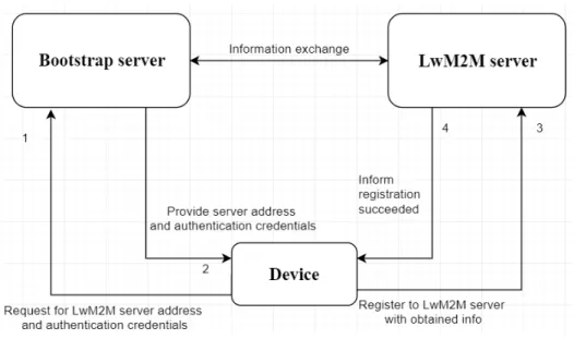
Bootstrapping is a term often refer to the process in which the first invoked program loads and executes more extensive programs, acting as a kickstart of the computer booting sequence. However, the bootstrap procedure in LwM2M does not imply this operation but instead denotes the act of which client retrieves useful information from a bootstrap server. This information contains the LwM2M server address and authentication creden- tial needed for the device to later successfully perform a registration. The bootstrap server is, in fact, an ordinary LwM2M server but its sole duty is to distribute necessary information so that clients can connect and register to the right server. There are four different bootstrap modes: factory bootstrap, smart-card bootstrap, client-initiated boot- strap, and server-initiated bootstrap [5, pp. 19-23]. Factory and smart-card bootstrap are as descriptive as it sounds, suggesting the necessary information is provided during fac- tory provisioning or coming from a smart-card. On the other hand, server-initiated boot- strap means the bootstrap server needs to push the required data to the client, but how does it knows the client need bootstrapping falls on implementation-specific. This sub- section only explains the client-initiated bootstrap procedure as it is the most straightfor- ward bootstrapping method. In this bootstrapping manner, essential information to con- nect to the bootstrap server is preloaded on the device, usually via factory provisioning or hard-coded inside the firmware. Figure 3 shows the process of a device-initiated boot- strap follows with registration to a device management server.
Figure 3. The process of a device-initiated bootstrap follows with registration to a device man- agement server.
Figure 3 describes the bootstrapping process of an IoT LwM2M device as follows [6]:
1) The device uses its pre-provided information stored in non-volatile memory to con- tact the bootstrap server. This information contains the bootstrap server address and security credential needed for authentication.
2) After connected to the bootstrap server, the device receives new information about the upcoming LwM2M server and a new security credential for authentication.
3) The device disconnects from the bootstrap server and uses the newly obtained in- formation to register to the LwM2M server.
4) Upon validated the client identity, the server sends an acknowledgement confirming that the registration has succeeded. The device is now considered registered and managed.
Even though this bootstrap procedure is not mandatory, there are many benefits to be derived from this feature, such as:
• The final bootstrap is executed after factory provisioning. As a result, the lat- est credentials in effect are not factory provisioned, thus lowering the risk of compromising device credentials during the manufacturing phase. In case devices failed to bootstrap due to their identities claimed, it might indicate that there is a security hole within the manufacturing process in which de- vice credentials are leaked.
• The manufacturer has an additional opportunity to detect defective devices before shipping by checking that the bootstrap procedure succeeded, hence verifying basics operation and connectivity of devices.
• After the device has been deployed on the field, the bootstrapping mecha- nism becomes an effective way to do re-keying, or merely redirecting the device to a different server. This feature will come in handy when the device credential is known to be compromised, or current managing server is going down for maintenance, or an ownership change of devices is expected (meaning devices are to be managed by another organisation’s server).
In summary, judging from the benefits coming from the bootstrapping feature, it is highly recommended to implement client-initiated bootstrapping functionality for the IoT device unless there are reasons to choose otherwise.
2.1.2.2 Device Monitor, Binding Mode and Fault Report in Lightweight M2M
Within the realm of LwM2M, a client needs to be registered to a management server to report its status and collected data. The specification defines a connection parameter called “Lifetime” which cites how long the client registration remains valid. In order to maintain a session, a client must renew its registration before this timer runs out, and such action is called a “Registration Update”. When the server receives such registration update from a client, the Lifetime timer for that particular session is refreshed, and the client must do another update before the next deadline, and so on. In case the client misses the deadline, it is considered deregistered from the server and its session invali- dated, thus, the client must redo the whole registration procedure again. Often this inci- dent signals that the device needs maintenance from a power outage, connectivity issue, hardware malfunction or software defect. Consequently, developers would like to con- sider an appropriate lifetime value for their devices which is harmony between how quick a downtime can be detected and how high is registration update frequency, a trade-off among quality of service and power consumption. Figure 4 illustrates the agenda of a client registration and a registration update between a client and an LwM2M server.
Figure 4. Client registration (left) and client registration update (right) flows. Copied from OMA Lightweight M2M specification [5].
At the beginning of a registration procedure, the client presents the server with its “End- point Name” (also known as client name), “Lifetime”, “LwM2M version”, “Binding Mode”
(not mandatory), and “Object Instances List”. All these connection configurations are provided by the client. Commonly, the client attempts a registration update to renew its session, but such operation can also be used to change the current lifetime value, or signify an update on the object instances list in case objects or instances were added or removed.
The binding mode is an important parameter determining the behaviour of the connection between client and server, which certainly play a significant role in power-constrained applications. This parameter specifies the transport binding (e.g. UDP, SMS) along with whether the “Queue Mode” option is applied. Queue mode is an interesting feature which benefits low-powered IoT devices that sleep most of the time and may only be reached during a short time window. As stated in the LwM2M specification, Queue Mode requires the server to queue its requests when the client is unreachable and send them out as it is reachable again. The client may notify the server that it is now awake by sending a registration update, thus they can exchange messages for some amount of time before the client goes to sleep and again unreachable. As a result, the most appropriate binding mode for low powered IoT devices is likely to be UDP with Queue Mode.
Furthermore, the LwM2M specification defines a mandatory “Device” object with the ID of 3, which is designated to report a set of generic information of the device, including battery level, power-source voltage, memory-free, error code, to name a few. In case the predefined object is not sufficient for a particular reason, a private organisation can de- fine its fault reporting object, or simply reuse a standard data reporting object. From a particular viewpoint, the device status is just another sensor value to be reported to the cloud, and it is up to the cloud server to make sense of it and determine the appropriate action, for example informing the operator about the low-battery state of the device.
2.1.3 CoAP in Lightweight M2M Service Enablement Interface
To grasp Lightweight M2M communication in-depth, one should know about CoAP char- acteristics as this protocol operates at one layer below LwM2M. In CoAP, messages are exchanged asynchronously between endpoints, often via unreliable transports like UDP in which data might fail to be delivered or arrive in an out-of-order manner. To counter this intrinsic drawback, this protocol defines two lightweight reliability ensuring methods:
• Stop-and-wait retransmission with back-off time for confirmable message.
• Duplicate detection with message ID.
Figure 5 gives an example of the differences between reliable and unreliable transmis- sion.
Figure 5. Illustration of reliable and unreliable transmission in CoAP.
There are four types of message in CoAP based on transport behaviour: confirmable (CON), non-confirmable (NON), acknowledgement (ACK), and Reset (RST).
• CON message requires an acknowledgement message (ACK) from the re- cipient. The sender will retransmit the same message at an exponential increase interval until the max number of attempts reached, or a matching reply is received, either it is a RST or an ACK.
• RST message is sent as a reply by the recipient in case it receives an empty, or unprocessable message due to lack of context. This behaviour holds in both cases where the orphan or invalid message is either CON or NON message.
• NON message does not require an acknowledgement from the recipient.
This message type is particularly useful in case a particular piece of data (e.g. room temperature) needs to be sent at a regular interval. To increase the delivery rate, the sender can send out multiple copies of the same mes- sage. Though this approach indeed increases the reliability of messages, it also causes an increase in the network load.
Regarding the request/response semantics, CoAP operates with a client-server archi- tecture and supports four basic methods: GET, POST, PUT and DELETE which is similar to HTTP’s scheme. Furthermore, CoAP also supports the use of URI to enable access to associated information on the device. As a result, it is feasible to make a CoAP device operate as if it is a simple web application with the help of a CoAP-HTTP proxy.
2.1.4 Lightweight M2M Resource Model and Information Reporting
A Lightweight M2M client consists of a set of objects, each of which contains multiple resources identified by unique IDs. These resources together form an interface for LwM2M server to acquire data from its clients. Both client and server need to have a consensus on the data type (e.g. string or float) of resources to avoid misinterpretation.
A resource within an object can be addressed via a URI in the {Object_ID}/{Object_In- stance_ID}/{Resource_ID} format. The semantics of these IDs are determined in ad- vance, thus the server can map or interpret the incoming data appropriately in the light of the circumstances.
The IPSO Smart Objects Working Group (IPSO WG), a joined force between OMA and IPSO alliance, proposes a list of LwM2M objects called IPSO smart objects as an attempt to standardise object models used for data reporting, providing a high level of interoper- ability for services and devices using LwM2M protocol [7] [8]. The data model of an LwM2M object comprises four parts:
• Object representation (Semantic)
• Data types
• Operations (Read/Write/Execute)
• Content format
Let us examine the IPSO temperature object definition as an example. Figure 6 presents the IPSO Temperature object definition.
Figure 6. IPSO Temperature object definition. Copied from openmobilealliance.org [9].
As presented in Figure 6, the temperature object is assigned ID 3303, and a client can contain multiple instances of this object type. As the case may be, different instances of the same object will represent different temperature measurements acquired by the sys- tem, such as room temperature, device internal temperature, or dew point temperature.
These object instances can be interpreted differently according to the client context and are out-of-scope of the IPSO objects definition. For the sake of explanation, assuming the object instance ID has a value of 0, then its sensor value can be accessed via
“3303/0/5700”. According to IPSO object definition, performing a read on this URI from the server-side would return the latest temperature measurement as a floating number.
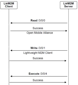
On the other hand, the device has to reject other operations performed on the said URI with an error code. Failing to follow this compliance can cause data misinterpretation or security risk (e.g. compromising the private key in the server object via a supposedly illegal read operation). Figure 7 presents the Interaction between LwM2M client and server on read, write and execute operation.
Figure 7. Interaction between LwM2M client and server on read, write and execute operation.
Copied from OMA LwM2M Technical specification [5, p. 34].
Lightweight M2M defines three basic operations that can be performed on a resource:
read, write, and execute. There are more sophisticated actions that can be performed, including create, delete, write-attribute, and discover which is not going to be discussed as they are advanced features which are not yet commonly used in embedded devices.
As the name suggested, read operation allows reading the current value of resource or object, write operation changes a value on client-side, and execute operation will trigger pre-defined action on the client (e.g. device reboot). Figure 7 above describes how these operations are carried out in practice in an illustrative manner.
Lightweight M2M defines an information reporting mechanism to enable LwM2M server to keep track and get notified when new values are available on client-side, which is called “Observation”. The advantage of applying this observation pattern is once the server has subscribed to the client’s objects or object resources of interest, the client will voluntarily push changes to server when value update is available, thus eliminating the need for server polling for updates. The notification coming from client is an unreliable CoAP message; hence, it is not possible to detect if packets are failed to deliver in case the transport layer does not guarantee delivery (e.g. UDP). Despite the fact there might be no guarantee of delivery from the transport layer, the situation may not as disastrous as it sounds as the usual delivery rate is high enough for most IoT applications, and
CoAP does offer a reliability mechanism when needed as mentioned in Chapter 2.1.3.
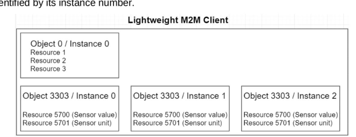
Section 4.5 discusses further the reliability of UDP and whether it is sufficient for IoT applications. Figure 8 provides an example of a (partial) LwM2M client consists of an Object of ID 0 and three instances of object ID 3303 (IPSO temperature object), each identified by its instance number.
Figure 8. An example of a (partial) Lightweight M2M client.
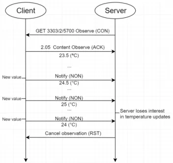
To illustrate this observe and notify mechanism, assume a situation in which an LwM2M server would like to keep track of changes in an imaginary room temperature reported at URI “/3303/2/5700”. Figure 9 describes the procedure of observing and notifying in LwM2M protocol.
Figure 9. Information report via notification mechanism. Copied and modified from OMA LwM2M specification [5, p. 40].
First, the server initiates the observation by sending an observation request specifying the resource of interest, which will then be replied with an acknowledgement and the latest value of the resource. From that point, whenever the client has a new value update on the observed field, that value will be pushed to the server as a notification. Since there is no acknowledgement for a notification, it is straightforward to see that the notification should be idempotent to prevent unexpected complications. In the case of no longer having interest on the observation, the server can terminate this relationship by sending an “observation cancel” to the client after it receives a notification, indicating that it does not want to receive more notifications on that resource. Other existing observations are not affected by this cancellation.
Currently, there is no definition for notifying with acknowledgement in LwM2M, which are supposed to be useful on resources more important compared to others. As a limited workaround, the client can always send the same notification update more than once, maybe by pretending they are different consecutive updates with an identical value. As a matter of fact, a similar approach is used in Bluetooth Mesh to increase the probability for an unacknowledged message to reach its destination. However, this method should not be abused as it increases the device power consumption and may cause unneces- sary load for the network.
2.2 Narrowband Internet of Things (NB-IoT)
This section first gives an introduction on NB-IoT, then later dives deeper into the funda- mentals of this technology from an application developer perspective. Discussions focus on NB-IoT connectivity behaviour at a high level while describing the power consumption patterns associated with connection states. Hopefully, these analyses give an insight into how NB-IoT works as well as how it favours low power application. Furthermore, the last sub-section provides a list of best practices to minimise the device power consumption.
2.2.1 Cellular IoT in Internet of Things Landscape
When it comes to IoT connectivity options, traditional non-scalable wireless technology such as WiFi and BLE is not suitable because of their shortcomings in large scale de- ployment, which generally makes way for two other alternatives: mesh and cellular.
These two approaches impose different advantages and disadvantages, therefore, the application requirements need to be taken into account when making decision on which technology to use.
Wireless mesh is the type of technology in which devices talk to their neighbours to form a network, making it feasible for outside-of-direct-radio-reach nodes to communicate. On the other hand, in the cellular world, network devices known as user entity (UE) have to talk with a base station, thus traffics will go through the network operator’s system. Table 1 provides a concise comparison between wireless mesh and cellular.
Table 1. A brief comparison between wireless mesh and cellular. Modified from digi.com [10].
Number of devices Network characteristics Device communication Mesh
Many devices in the same location
Does not need cellular coverage
Can be self-healing
Favours communication with network neighbours
Cellular Only a few devices in the same location
Need network coverage Devices communicate mostly with cloud server
As stated in Table 1, mesh networks are convenient for applications where many devices are at the same location, and mostly communicate locally. For example, Wi-SUN is a popular mesh solution for street lighting control as the lights can conveniently talk locally, while self-healing properties of mesh network keep the operation reliable. Many cities around the world, such as Miami and Paris, have deployed their wireless control lighting infrastructure, thus proving that this technology is indeed a practical solution [11].
On the other hand, the cellular approach is viable for devices prefer direct communication with the cloud. A few examples of applicable cellular systems are smart electricity meter and smoke detector. There are a lot of exciting developments in progress for NB-IoT and
LTE-M, both of which are subsets of the standard LTE. These two newly emerged tech- nologies, especially at the sunset of 2G and 3G around the world, aim to satisfy the market demand for low power and long-range cellular.
Despite the fact of having different characteristics and area of usage, these two technol- ogies can be complementary to each other. A good illustration for this statement is using a mesh network for sensor nodes and a few cellular nodes as network gateways. Con- sequently, this set up benefits from mesh scalability while keeping the cost in check as the product maker does not have to install a cellular module in every unit [12]. A few low- power mesh technologies to be named are Bluetooth mesh, Thread (6LoWPAN based), and Zigbee. Moving back to the main topic, this paper now focuses on NB-IoT – a cellular LPWAN technology.
2.2.2 Narrowband Internet of Things
Narrowband Internet of Things (NB-IoT) is a new low-power wide-area network technol- ogy introduced in the 3GPP Release 13 (2015) that aspires to enable a wide range of new IoT applications with improved power consumption, system capacity, spectrum effi- ciency, and support extended coverage. It has been estimated that a single NB-IoT base station can support 50,000 devices, while battery-powered NB-IoT devices can operate up to 10 years under specific conditions. Figure 10 highlights the landscape of IoT &
Machine Type Communications (MTC) with two ends of the spectrum: massive MTC and critical MTC.
Figure 10. IoT applications and Machine Type Communications. Copied from: qorvo.com [13].
The massive MTC category consists of LPWAN technologies that can support a tremen- dous amount of devices, while critical MTC technologies offer reliable real-time commu- nication. Within this outlook, NB-IoT inclines towards the massive MTC side as its char- acteristics favour a massive number of low-cost and low-power consumption devices targeting data-collecting applications. Figure 11 lists out three different spectrum deploy- ment alternatives in deploying NB-IoT.
Figure 11. Operation modes in NB-IoT. Copied from "Narrowband Internet of Things whitepaper"
[14, p. 9].
The first option shown in Figure 11 is standalone deployment in which NB-IoT carrier reuses an existing GSM band. The second option, in-band deployment, is occupying a part of the LTE carrier for NB-IoT usage. The last alternative, guard-band deployment, is deploying NB-IoT within in the LTE guard band. The physical layers of NB-IoT have been designed to operate in this option without hindering the existing LTE. Fortunately, an LTE base station, often built upon software-defined radio, requires only a software
upgrade to support NB-IoT, thus making it convenient to upgrade most of the existing LTE networks to support this new technology. Figure 12 shows the current deployment state of IoT cellular networks around the world by June 2019.
Figure 12. Mobile IoT cellular network deployment map (Jun 2019). Source: www.gsma.com [15].
According to the GSM Association, by May 2019, there have been 114 operators around the globe supporting NB-IoT and/or LTE-M [16]. At the dawn of cellular IoT, despite the fact LTE-M got more traction in the US, the rest of the world prefer to roll out NB-IoT first.
Consequently, NB-IoT is the better option for IoT applications which does not target the US market. At the moment, all major network operators in Finland including DNA, Elisa and Telia provide support for NB-IoT, but only DNA offers LTE-M. Coming from the fact that Finland has excellent LTE coverage in residential areas [17], it would be reasonable to predict that NB-IoT devices are going to have a great opportunity within cities since they will receive strong signal, thus promise quality service.
2.2.3 NB-IoT Connection States and Low Power Features
Although NB-IoT is currently known as the most energy-friendly cellular technology in the licensed band, understanding what are the energy components in an NB-IoT con- nection is vital for developers to understand how to write proper firmware for low power
application. Figure 13 presents the state transfer diagram of user equipment (UE in terms of energy components.
Figure 13. State transfer diagram of NB-IoT energy components. Copied from “Energy Modeling and Evaluation of NB-IoT with PSM and eDRX” [18].
The chart in Figure 13 comprises six different states:
• Connected (RRC-connected): The UE is in RRC-connected state and can exchange data – exhibits a high power consumption.
• Uplink (RRC-connected): UE radio sends data uplink when software sends new packets to the destination server – exhibits a high power consumption.
• Downlink (RRC-connected): UE receives downlink data when there is data sent to the device - exhibits a high power consumption.
• Paging (RRC Idle): UE is monitoring paging messages from the base sta- tion in its RRC-Idle state - exhibits small spikes in power consumption graph due to the radio reception.
• Idle (RRC Idle): UE waits for the next paging cycle or goes to power saving mode (PSM) if T3324 expires - exhibits a low power consumption.
• PSM (RRC Idle): UE turns off the radio for a long time and sleeps until T3412 expires or an uplink request came from the microcontroller - exhibits lowest power consumption.
Figure 14 shows a simpler illustration of NB-IoT operating modes from the application standpoint.
Figure 14. U-blox SARA-N211 module operating modes from an application perspective. Copied from “SARA-N2 series system integration manual” [19, p. 11]
Fortunate for developers, they do not need to know extensively about all the state tran- sitions featured in the NB-IoT protocol as certified modules (e.g. SARA-N211) already managed these transitions, curtailing away a huge amount of responsibility from devel- opers. The following Section 2.2.4 further explains two important timers T3324 and T3412 and gives a more descriptive example of the power consumption in a typical us- age scenario.
2.2.4 Power Saving Techniques in NB-IoT
There are two features in NB-IoT to optimise the power consumption: connection release and resume; extended discontinuous reception (eDRX) in conjunction with power-saving mode (PSM). These features together help reduce the power consumption significantly, making it viable to create a battery-powered IoT device that may deliver the ten-years theoretical expectation.
Figure 15 describes UE operations in a typical NB-IoT usage scenario. On the top, there is the RRC connection state; the middle represents the activity between UE and base station in corresponding to power consumption; the bottom indicates whether the radio is enabled. Also, the power consumption in each event is presented accordingly, except for the PSM mode which actually is the state with the lowest power consumption.
Figure 15. Summary of UE’s behaviour in NB-IoT associated with power consumption. Copied from “Exploring the Performance Boundaries of NB-IoT” [20].
For power-constrained wireless application, the power consumption is in tight correlation with the radio activity. The prevalent strategy to conserve energy in such applications (e.g. BLE) is to schedule communication time window in advance for both sides, allowing the radio to turn off between these intervals. Without any surprise, this philosophy is indeed applied in NB-IoT.
At first, the UE goes to “RRC-connected” state as it sends out a mobile originated packet to the network, which could be triggered by the application code sending a UDP packet, or there is a tracking area update (TAU) to be performed. As a matter of fact, the UE can jump to this RRC-connected state at any point as it sends data to the base station. Next, the UE proceeds to wait for mobile terminated traffic and monitor Connected-eDRX (C- eDRX). Mobile terminated traffic is simply a term for a message sent from the network to the UE, as such message is terminated at mobile/UE side. After the “Inactivity Timer”
expires (in fact this transition comprises few timers according to LTE specification), the module transits to “RRC-idle” state and starts monitoring Idle-eDRX (I-eDRX), at the same time it starts the “Active timer” (T3324) and “TAU timer” (T3412). During this state, the UE can sleep between paging occasions to reduce its power consumption. Paging occasions are time window in which the network can inform UE if there is a downlink packet for it, which will trigger UE to resume RRC-connected state to exchange data with the base station. Otherwise, when the “Active timer” (T3324) expires, UE will go to PSM
- the lowest power state and remains unreachable by the network until “TAU Timer” ex- pires or UE’s application sends a packet uplink. At such events, the UE goes to RRC- connected state and is again ready to exchange data with the network. This connection release/resume mechanism is achievable as UE retains its network session context to avoid the overhead of renegotiation with the network. Figure 16 presents a typical power consumption pattern of a UE as described earlier.
Figure 16. Modem current consumption from power-on to deep sleep mode visualised. Copied from SARA-N2 Series System Integration Manual [19, p. 13].
With the illustration in Figure 16, it would be simpler to recognise the power pattern with- out being distracted by connection states and radio activity information.
The purpose of eDRX and PSM in NB-IoT UE is to reduce receiver enabled time to save power at the cost of connection latency. In layman’s terms, the eDRX feature means the specifications now allows longer time duration between pagings. There are two eDRX types: Connected eDRX (C-eDRX) and Idle eDRX (I-eDRX). Even though the ultimate decision on connection parameters is up to the network, however, the UE can provide its preferred values for Active Timer (T3324), TAU Timer (T3412), paging window (de- noted as Tpw in Figure 15), and eDRX cycle. Unfortunately, the “Inactivity Timer” and C- eDRX cycles are chosen by the network and UE cannot influence these parameters, but that also means there is less responsibility for the application developer. Developers should contact network operators to ask for supported network parameters choices since they may not allow all possible values listed in the 3GPP specifications. Also, it is worth noting that the network can change these connection parameters at any time. Appendix 1 provides a lookup table on how to encode eDRX and paging time window value. Ap- pendix 2 supplies instruction on encoding T3324 and T3412. Figure 17 brings more de- tails on eDRX regarding paging procedures in an illustrative manner.
Figure 17. Magnified power consumption pattern of NB-IoT UE in paging procedures. Copied from Keysight NB-IoT Technical Fundamentals [21, p. 25].
Release assistant is a feature for UE to actively release the connection and go to RRC- Idle as soon as possible, which is especially beneficial for battery-powered devices.
When the UE transmits a data packet uplink, it can use Release Assistant feature to notify the base station that either only one downlink response from the cloud is expected so the RRC will be released after the next downlink, or no further downlink is expected and RRC resource will be released right after the uplink transmission completed. If this feature is not used, the UE will be staying in RRC-connected state for a relatively long time (e.g.10-30s) depending on the network config before transiting to IDLE, which can be considered energy wasting. Figure 18 describes the power consumption patterns of an NB-IoT module sending a 512 bytes datagram under different network settings.
Figure 18. Power consumption of NB-IoT module sending a 512 bytes datagram under different network settings. Copied from “Exploring the Performance Boundaries of NB-IoT” [20].
For identifying operations of the UE, the module exhibits a deep sleep current of 3uA, 10 mA in Idle (which in fact differs from the observation made during this thesis as during the Idle state outside paging occasions the module has the same consumption as during deep sleep), 60 mA when radio is in reception mode and 200mA when radio transmits.
In situation (1) and (4) UE disabled the I-DRX by setting T3324 to 0, while in (2) and (4) this timer is set to 20s. Situation (1) and (3) are nearly the same, and the only difference is (3) uses release assistant to conserve power by avoiding staying in RRC-connected state. On the other hand, (2) and (4) have the same settings, but in (4) there is a downlink during UE I-DRX monitoring process. This downlink message brings the UE to RRC- connected, and after receiving the message, the module spends some time monitoring C-DRX and I-DRX before going to deep sleep, meaning the Active timer (T3324) got reset by this downlink. This behaviour should be taken into account while developing applications. Figure 19 provides a summary of eDRX related connection parameters in NB-IoT.
Figure 19. Summary of eDRX related connection parameters in NB-IoT. Copied from “Exploring the Performance Boundaries of NB-IoT” [20, p. 4].
Figure 19 provides a table of summary of NB-IoT eDRX related timers mentioned in this section, coupled with information indicating whether the UE can suggest them. The TAU timer (T3412) is left out due to not related to the eDRX process, is suggestable by UE, making a total of six parameters to keep in mind during development.
2.2.5 NB-IoT Power Consumption Best Practices
The power usage of a device is determined by multiple factors, each of which if not ap- propriately engineered, could ruin the expected power efficiency. This section provides some tips to follow to optimise the device power consumption:
• Design a good PCB layout to reduce interference on the device. Be careful with antenna matching circuit.
• Carefully choose electronics components suitable for low-power operation to minimise quiescent current of the device. Sensors and peripherals need to be put in a low-power state while being unused.
• Select appropriate preferred configurations for T3324, T3412, eDRX cycle length and paging time window for the application requirements. Develop- ers are recommended to ask the network operator if those configurations are accepted in their network. Experimenting by trial and errors is time- consuming.
• Use the NB-IoT release-assistant feature properly within the application.
Set the device uplink power accordingly while avoid operating the device in coverage enhancement level 2.
NB-IoT currently only supports open-loop power control, meaning UE determines its transmitting power. There are two transmit power levels of 23 dBm and 20 dBm sup- ported by CAT-NB1, and 14 dBm added in CAT-NB2. To enhance coverage for IoT de- vice, UE is classified into Enhancement Coverage Level (ECL) ranging from 0 to 2 in
which 2 is the worst-case scenario according to the signal strength received and report by UE. This classification determines the number of repetition of the transmission to en- sure the quality of service, but at the same time drives the power consumption of UE up with increased air time. As this issue depends on the physical deployment, the device is recommended to report its coverage class to the cloud server so maintainer can detect it to take appropriate actions such as deploying it at an alternative location.
2.3 Mbed OS
Mbed OS is an open-source operating system developed by ARM and its silicon part- ners, designed specifically for ARM Cortex-M microcontrollers. The operating system aims to simplify the device software development process by offering a common abstrac- tion layer across multiple microcontroller series from different vendors including NXP, ST, Cypress, etc., hence reducing time-to-market for embedded devices in general and IoT devices in particular. Furthermore, this approach allows applications developed for Mbed OS to be migrated among Mbed compatible platforms with reasonable effort. Fig- ure 20 gives a high level illustration of Mbed OS, presenting the framework’s architecture and its main components.
Figure 20. The architecture of Mbed OS. Copy from os.mbed.com [22].
First of all, Mbed OS attempts to unify commonly available functionalities in microcon- trollers, for instance, UART, I2C, Timer, etc … under the same C++ application program- ming interface (API), making it virtually identical to configure and use a peripheral throughout the Mbed ecosystem, hence promoting code reusability. Apparently, this API unification also set up a good starting point for adding support to new targets or new features into existing targets.
Second, MBed OS comes with support for many software modules related to sensor drivers, data storage and connectivity. The availability of off-the-rack sensor drivers en- ables a quick and straightforward solution for integrating new sensors into the system.
Besides, the OS also facilitate external data storage capability on SD card or SPI/QSPI flash. On the other hand, there are connectivity supports built-in in the OS to reduce the complexity of making an IoT device. Thanks to this flexibility offered by Mbed, developers can make their device supports IP based connectivity via Ethernet, WiFi, 6LoWPAN, cellular, or other forms of non-IP communication such as BLE, NFC.
Third, Mbed OS includes an RTOS for developing software with deterministic, multi- threaded, real-time execution. This component equips developers with RTOS primitives including threads, mutexes, semaphores, queues as well as other standard RTOS func- tionalities to accommodate the application requirements. The RTOS feature can be ex- cluded if not needed in the program to save RAM and flash consumption.
Moreover, the ARM MBed team provides a list of comprehensive API documentation along with examples and tutorials on their website. As a result, these materials help de- velopers to get familiar with MBed API as quickly as possible and help them to start developing their customised system.
Another perk offered by Mbed OS is Greentea, an automated testing tool. Tests are written in C++ as if it is a regular MBed based program, which will be executed directly on the microcontroller. On the one hand, this testing tool minimises the amount of labour needed since it handles all the device flashing as well as the test result collecting process from device-under-test (DUT). On the other hand, Greentea support “host-test” features which under the hood are Python scripts that run on a computer and communicate with the microcontroller. For example, a tester can write a test case in which the host machine
request DUT to send a specific piece of data to the cloud and then check if the same data is received on the cloud side, verifying the DUT connectivity capability. Since em- bedded applications are much less convenient to test compared to a pure software ap- plication, this automated tool is an excellent effort towards minimising the hassle of em- bedded testing, which will consequently promote better quality for IoT projects [23].
3 Design and Implementation
This section dives into the technical aspects of the project, starting with the goal and requirements of the project, then visits the system components selections and system architectural decisions along with relevant processes including testing and optimising the device power consumption. These contents should provide readers with an overall un- derstanding of the system, and at the same time, give an outlook on how the project was carried out.
3.1 Project Goal and Requirements
This thesis was carried out as part of a client project at Etteplan Embedded Finland Oy to evaluate the capability of NB-IoT, LwM2M, and Mbed OS. Moreover, the artefacts of this project will be used as a reference design to shorten the execution time of future projects relying on the same technology stack and similar electronic components. This
“Design and implementation” section focuses on the software aspect of the system as it aligns with the author’s duty throughout the project.
Regarding functionality specification, the device is expected to take data from a weather station via Modbus protocol and send reports on environmental measurements and its operating state to a cloud server over NB-IoT. Besides, the cloud server should be able to execute predetermined operations on the device, for example, rebooting. On the other hand, the whole system should operate as efficient and low power as possible.
3.2 System Components Selections
Choosing system components, one of the first and arguably the most crucial step, deter- mine the foundation of the system. This subsection lists out hardware and software com- ponents along with commentaries why they are chosen.
3.2.1 Main Hardware Components Selections
One of the first steps in designing a constrained, low power IoT embedded device often is selecting the target microcontroller. After some research, an MCU from the STM32L4 family is selected for several reasons. First of all, ST Microelectronics is a well-known semiconductor provider in Europe offering a diverse portfolio of microcontrollers for a wide range of technical requirements. Second, Etteplan has delivered many successful projects which incorporates STM’s components, including the selected MCU. Conse- quentially, software and hardware designers at the company are already familiar with the properties of this microcontroller as well as its development ecosystem. Third, the MCU offers a hefty amount of flash and RAM, along with multiple peripheral instances of UART, I2C, and SPI that presumably cover the expectations of the application. Though this pick might not be the ideal choice for large quantity production, it is sensible to pri- oritise creating a few working prototypes with as little hassle as possible at the project start. When it comes to an economic incentive for revising components in case of mass production, it is feasible to migrate the system to a less costly pin-compatible MCU within the same family, which would offer reduced ROM and/or RAM while still satisfying re- quirements [24]. Fourth, STM32L4 family is an ARM Cortex-M4F explicitly designed for low power applications [25], considering one of the key requirements of the project. Last but not least, the selected MCU is officially supported by Mbed OS, making the software development much more straightforward as there is no need to port the framework to the target.
Another essential physical component in this project is the NB-IoT modem, of which eventually U-blox SARA-N211 got selected. Just in case this brand name sounds unfa- miliar, U-blox is a reputable wireless module provider known for offering high-quality pre- certified modules regarding WiFi, Bluetooth, GNSS and cellular [26]. Etteplan has previ- ously conducted projects that use U-blox modem and feels confident in trying out this
NB-IoT module. Moreover, U-blox defines consistent footprint formats for their compo- nents, in this case, a form factor named SARA, making it convenient to migrate among modems with the same form as it reduces the effort needed for redesigning the sche- matic and PCB layout. On the other hand, this CAT-NB1 module is capable of operating in bands 8 and 20, compatible with networks in Finland. In future projects, it is possible to swap the modem to a SARA-N3 which support more frequency bands and CAT-NB2, or to SARA-N4/R4 if LTE-CATM1 or 2G fallback is requested. Another advantage of using U-blox products is that the company provides detailed materials necessary for soft- ware and hardware designing processes, and has always been responsive to customer support.
3.2.2 Software Component Selections
In the present project, Mbed OS was selected as the base for the firmware by the ad- ministration. While this may be true, this framework is, in fact, an appropriate choice for the system thanks to its ideology of unifying APIs to simplify development and attempts to provide proper support for external components. Mbed OS has been under active development by ARM and its partners for the last ten years, making it one of the most mature frameworks for microcontroller-based IoT device available. Equally important, the framework is open source and has been licensed under Apache 2.0, MIT, BSD along with a few royalty-free permissive binaries, thus making it applicable to commercial pro- jects.
Another significant point of consideration was determining which IoT protocol to use.
Again, Lightweight M2M was chosen by the administration and therefore used in this project. Genuinely, LwM2M is a good pick for several reasons. First, unlike the MQTT protocol operating on TCP, LwM2M can be used on UDP, which happens to be the only IP based protocol supported by SARA-N211. Second, the use of connectionless UDP favours low energy consumption as TCP protocol requires the device to stay awake and maintain the connection. Wakaama, an opensource lightweight M2M library backed by Eclipse, was selected due to practicality and financial reason. Interestingly, the built-in LwM2M client in U-blox N2 modem (not used in this project) is also based on the same library [27, p. 11]. From a subjective point of view, LwM2M is an unfamiliar name com- pared to MQTT as it is a latecomer of the IoT world and yet to be supported by major
cloud services. Fortunately, there are currently a few providers on the market support LwM2M such as ARM Pelion or Cumulocity IoT. Hopefully this promising protocol will gain more traction in the future as it is designed as a full-fledge device management protocol with interoperability in mind.
3.2.3 Guide on U-blox SARA-N211 NB-IoT Modem
This section presents a summary with tips for integrating SARA-N211 U-blox NB-IoT modem with the device. First of all, the microcontroller can communicate with the module through an asynchronous serial interface (UART) without flow control support. This serial interface supports 8N1 frame at four different baud rates of 4800, 9600, 57600 and 115200 [19, p. 17], but selecting a baud rate higher than 9600bps (fastest supported by the Low Power UART of the modem) will disable deep sleep operations [28, p. 48]. Even though there is no flow control support, the module activity can be detected via the V_INT pin (active high). This property acts as an excellent trigger to enable the UART of the MCU. The notifying mechanism of the V_INT pin is illustrated in Figure 21.
Figure 21. Interfaces supply output (V_INT) simplified block diagram in SARA-N2 series. Copied from SARA-N2 series System Integration Manual. [19, p. 13]
The microcontroller controls the module by issuing AT commands – commands used for modem controlling named after its “AT” (attention) prefix. Commands supported by the module can be lookup in the “SARA-N2 AT Commands Manual” [28]. Most of the com- mands coming from the MCU are acknowledged by the modem nearly instantly, how- ever, the modem can issue an Unsolicited Result Code (URC) to the MCU at any time.
URC serves as a way for the modem to actively notify the MCU, for example reporting a
change in network registration state or a newly arrived UDP packet. For this reason, the module’s activity indication via V_INT pin comes in very handy, especially for low power device where the more power-downed peripheral, the better.
Coming back to the software perspective, whenever the application wants to send data to a cloud server, it first needs to open a socket with a specified destination IP address and port. Thanks to U-blox implementation, the N211 module comes with an embedded UDP stack, freeing the responsibility of having to accommodate a TCP/IP library (e.g.
lwIP) for application developers. However, this pre-packaged convenience only supports UDP IPv4, thus binding the system with UDP and IPv4 issues. Fortunately, this limitation does not apply with other modem lines such as U-blox SARA R4 which supports both TCP and UDP on both IPv4 and IPv6. According to U-blox’s manual, the module can only send and receive payload at a maximum of 512 bytes. However, based on obser- vation during the module usage, this statement turns out to be inaccurate as the stated limitation only applies to uplink, but not to downlink. When there are more than 512 bytes of payload sent downlink, the module still manages to receive the data correctly as the real limit is close to 1500 bytes (1500 bytes is Ethernet MTU). This matter is revisited with more details in Section 3.7.
A minor issue with this U-blox module is that it does not give out any indication when an uplink packet is dropped. Even though this is not considered misbehaviour by the nature of UDP, it has been observed that the modem drops some packets when there is a rel- atively large amount of them sent uplink at once, decreasing the quality of service. De- velopers may want to safeguard their implementation with a self-regulating packet pace mechanism to avoid congestion on the module. This congestion is easy to reproduce by sending many packets consecutively (e.g. ten packets, each of 400 bytes) when the module connection is not yet in the RRC-connected state.
3.3 Development Environment and Team Collaboration Workflow
It is known that a well-established development environment and positive collaboration among team members play an essential role in working efficiency. With this wisdom in mind, team members discuss and settle on a common development environment as well as rules for the Git workflow. The integrated development environment (IDE) chosen for
this project is Eclipse CDT (also known as Eclipse for C/C++) with GNU MCU Eclipse plugin. The debugger used is ST-Link-V2 in conjunction with OpenOCD. The chosen compiler is GCC-ARM, and the build tool is Mbed CLI – a tool provided by the Mbed team to simplify the development process, including building and testing the application.
Program traces are collected via UART and can be displayed on PC with an USB-to-TTL adapter. These setup decisions turn out to be cost-effective as these tools are quite easy to set up, at the same time, offering extensive yet convenient features at a minimal cost.
Eclipse is a well-known IDE maintained by the reputable Eclipse Foundation who houses over 350 open-source projects across a wide range of technologies [29]. According to the release log, Eclipse CDT receives a new update every three months, indicating the IDE is under active development and maintenance. On the other hand, GNU MCU Eclipse is a well-maintained plugin for Eclipse CDT which provides an extensive set of tools for ARM and RISC-V MCU at no cost. As a result, many silicon providers like ST and NXP provide customised Eclipse CDTs as recommended IDEs for their clients. From an embedded developer perspective, this toolset provides a functional text editor, a flex- ible way to configure the build process along with good integration with debugging utilities including GDB, OpenOCD, and JLink. Furthermore, the IDE offers a peripherals register view which enables developers to quickly inspect peripheral registers whenever the tar- get is stopped, thus speeding up the debugging process, especially for low-level driver developments.
The project execution follows the Scrum methodology. About Git policy, the team decides to use interactive rebase instead of merging. Rebase before merging into master is not a problem within a small team, yet it makes the history on the master branch linear and simple to follow. Furthermore, a merge request must pass the CI pipeline and got ap- provals before getting accepted. As the CI process consumes time and requires starting up a physical machine, team members agree that pipelines are only required to run be- fore merging and for every commit on the master branch.
3.4 System Design and Software Architecture
The primary responsibility of the program is similar to a generic IoT data collecting sys- tem, focusing on gathering sensor measurements and push them to the cloud for post-
processing. While this may be true, project steps are not as straightforward as they usu- ally are because the design involves new technology stack with limited supporting mate- rials. The first obstacle is porting the LwM2M Wakaama library from working with the POSIX interface to using Mbed OS APIs. In the beginning, this task was difficult and had no clear direction as the library does not come with any guide or instructions to achieve such a goal. However, the right path to the solution was soon revealed after the example code had been skimmed through and its execution flow followed by adding printing state- ment as well as using a debugger. As a matter of fact, the developers of the library has designed their code with portability in mind, defining wrapper facade functions for setting up and tearing down connections, at the same time designating a function to send data as well as a function to pipe received data into the library for processing. For this reason, even though the example code depends heavily on POSIX calls, the library is loosely coupled with this interface and can be ported to another platform by rewriting the men- tioned functions appropriately and make minor changes on piping the received data into the library.
Regarding the architectural aspect, the firmware architecture strictly follows the gate- keeper design pattern. Gatekeeper pattern [30, p. 260] is a designed pattern in which only a task, the gatekeeper task, has sole ownership of a particular resource, and only it is allowed to use this resource directly, while other tasks can only use the said resource indirectly via the service offered by this gatekeeper. As a result, this pattern ensures mutual exclusion in accessing the resource while avoiding priority inversion or deadlock.
Furthermore, as only one task has direct access to a resource, it will be easier to identify and resolve the issue in case one happens to arise. Figure 22 supplies a hardware block diagram, listing out components that physically comprise the system.
Figure 22. Hardware block diagram of the system.
As Figure 22 illustrated, there are multiple components within the system including sen- sors, external flash and cellular modem, which could be quite a challenge to manage in a single-threaded application. Figure 23 presents the structure of the software, focusing on threads’ responsibilities and how do they interact with others following the gatekeeper pattern.
Figure 23. The software structure of the IoT application.
Generally speaking, the program consists of three major threads: main thread, sensor thread, and watchdog thread, each of which has distinct duty within the system. First,
the main thread is responsible for initialising the MCU, spawning other threads and af- terwards managing the communication with the LwM2M server. The second thread, sen- sor thread, takes care of initialising sensors and collecting sensor data. These sensor data will be relayed to main thread via a Mbed OS mail (similar to a pipe or a queue) to be pushed to the cloud. The third thread, watchdog thread, acts as a failsafe mechanism to rescue the system from unexpected unrecoverable failures with a reset.
3.5 Software Testing
Software testing, an element within the software quality assurance process, is an im- portant ingredient which safeguards the functionality of the program, allows work collab- oration between developers and promotes good coding practices. This section provides a list of testing methods applied and applicable to this project. The names of these will- be-mentioned techniques may not follow well-known conventions.
The first testing technique used in this project is manual white box testing. These tests are to be manually performed by developers to verify whether the connectivity and LwM2M proportions of the application works as expected. First, an LwM2M Leshan server is set up on an AWS instance to carry out the role of a bootstrap and device management server. Next, Tcpdump, a network analyser tool, is installed on the server to log network traffic on ports of interest as its log can be later analysed with Wireshark.
Fortunately, Wireshark provides support for decoding LwM2M and decrypting DTLS communication (provided the pre-shared key), thus making it a valuable utility to diag- nose the connection problem and verify whether network data are consistent with infor- mation sent from the device. In fact, this setup combines with the server’s log helped to resolve the DTLS handshaking failure while attempting certificate authentication. On the other hand, this setup also can provide an estimation on NB-IoT latency by measuring how long does it take for a ping to travel back and forth. Since NB-IoT latency can be in the degree of seconds, millisecond precision is not needed for this measurement. For instances, initial ping to google.com can take nearly 9 seconds, but subsequent ping will take much less time since the modem is already in the RRC-connected state. Later, this simple test can be improved and use to test out the reliability of the network at a given location. As Leshan server exposes a REST interface, it is possible to write an integration test which sets resources to different values then try to read it back from the device,

![Figure 4. Client registration (left) and client registration update (right) flows. Copied from OMA Lightweight M2M specification [5].](https://thumb-eu.123doks.com/thumbv2/9pdfco/1890506.266672/15.892.199.779.106.429/figure-client-registration-client-registration-copied-lightweight-specification.webp)

![Figure 6. IPSO Temperature object definition. Copied from openmobilealliance.org [9].](https://thumb-eu.123doks.com/thumbv2/9pdfco/1890506.266672/19.892.211.765.107.445/figure-ipso-temperature-object-definition-copied-openmobilealliance-org.webp)
![Table 1. A brief comparison between wireless mesh and cellular. Modified from digi.com [10].](https://thumb-eu.123doks.com/thumbv2/9pdfco/1890506.266672/23.892.172.814.572.769/table-brief-comparison-wireless-mesh-cellular-modified-digi.webp)
