En raison de leur nature massive, les antennes DRA ont également la possibilité de s'intégrer à des antennes métalliques 2D avec un couplage réduit. La bande passante d'impédance commune aux 2 ports est de 5,9% avec une isolation de -35 dB.
Problem statement
Figure 1.4: (a) Antenna with dual ISM band radiation pattern showing high degree of gate coupling (-3dB) (b) Deformed wideside radiation patterns (c) Deformed end-fire type radiation patterns. Chapter 5: It is devoted to actual measurements of antennas and evaluation of their Diversity Gain (DG) performance in the context of BAN.
Cylindrical DRA Characteristics
Resonant Modes
An isolated cylindrical DRA of radius "a" and height "h" on a large base supports three different modes: TE (to z), TM (to z), and hybrid. Usually this mode is excited in a split cylindrical shape for which the design formula is given in equations (2.4) and (2.5).
Typical Mode Excitation
It must be placed close to the peripheral boundary of the cylindrical DRA, either embedded inside or equidistant outside it, to produce the corresponding broadside radiation pattern. The TE01 looks like radiation pattern of half-wavelength narrow slot on the ground plane and directed to the axis of resonator.
Survey of Excitation Techniques
- Aperture Slot
- Coaxial Probe
- Microstrip Line
- Coplanar Feeds
- Hybrid combination of coaxial probe and aperture slot
- Similar combination of two aperture slots
A quarter wavelength can significantly improve coupling with a DRA, as its reactance is canceled by the gap reactance. The probe can be thought of as a vertical electric current positioned to achieve strong coupling with the DRA.
Bandwidth Enhancement Techniques
Simple Structures
Q-factors reduction
Impedance matching
Given individual design sizes, multiple elements are made to resonate at slightly separated frequencies, which are cleverly tuned to either merge to offer wider bandwidth or to separate to provide multi-band [28-29].
Ground Plane Effects
The size of the ground plane can be varied to see if it affects the radiation patterns. It is estimated that the front-to-back ratio can be improved to some extent by increasing the ground plane size and that can be attributed to the possible reduction of back-shifted radiation.
Circularly Polarised DRAs
The total radiated field E can be expressed by the vector sum of the fields GO (Ego) and the diffraction fields (Ed) as;. Using numerical methods, it was found that the finite ground plane introduces ripples in the front and back radiation patterns that are not present in the infinite ground plane.
DRA Arrays
Fig2.26 (a) Cross slot coupling of unequal slot lengths (b) 4 elements sequentially rotated microstrip fed circularly polarized array [1]. So one is limited to rely on some alternative methods, but at the cost of some variations in the expected results.
Conclusion
18] G.P. Junker, A.A. Kishk and A.W.Glisson,” Input Impedance of Dielectric Resonator Antennas Excited by a Coaxial Probe”, IEEE Trans. Ittipiboon and J.S.Wight, "Investigation on a Microstrip Fed series array dielectric resonator antenna", IEE Electronics.
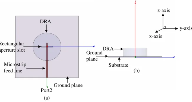
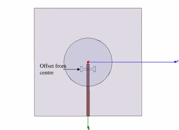
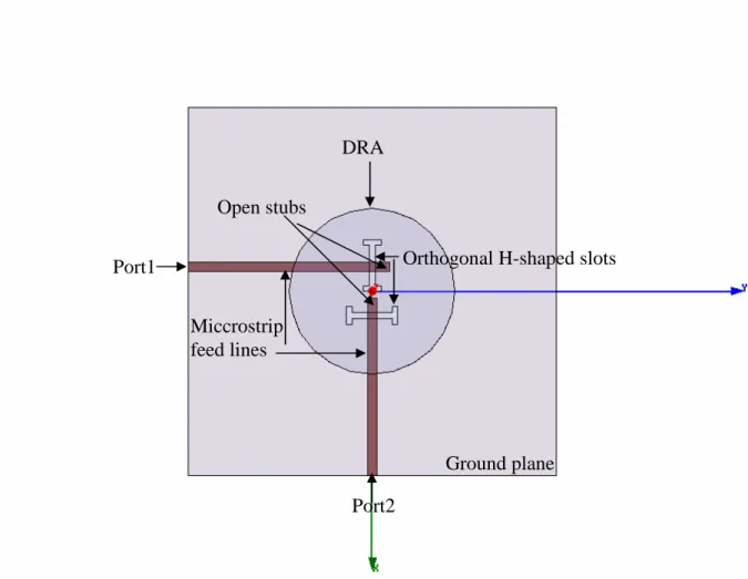
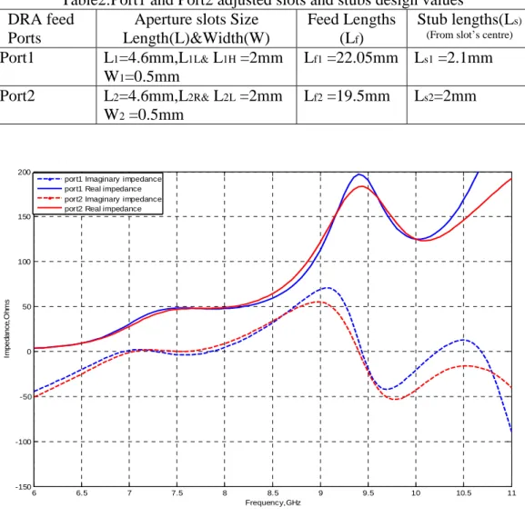
Design of an aperture-coupled cylindrical DRA
Estimation of aperture slot length
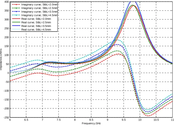
It should be noted at what stub length the imaginary part of the impedance simply becomes zero. The level of co-polarization in both planes is found to be nearly 30dB higher than that of cross-polarization in the broad direction.
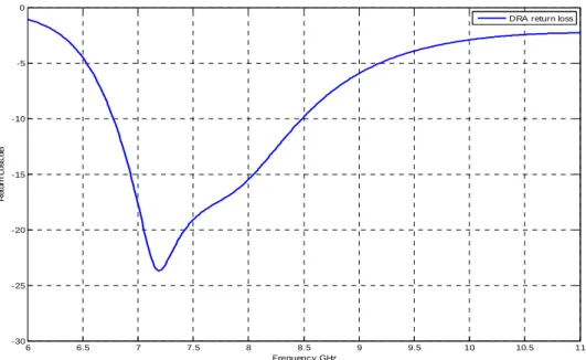
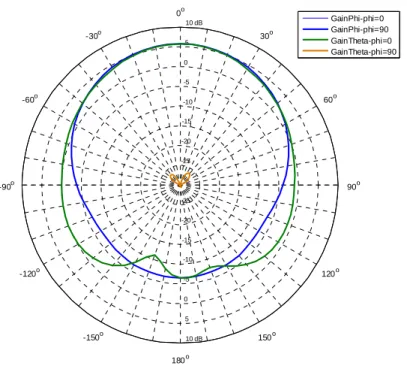
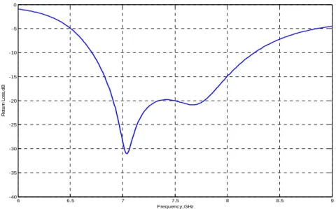
Single port (Port1) performance analysis
It is found that the E- and H-plane radiation patterns are symmetrical at 7.3GHz frequency, but E-plane pattern becomes slightly asymmetric when shifted to 8GHz. The 3dB Half Power Beam Width (HPBW) is of 90°, but E-level pattern as in port1 case is slightly wider towards the horizon.
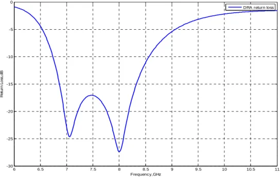
Dual ports (Port1 & Port2) combined performance
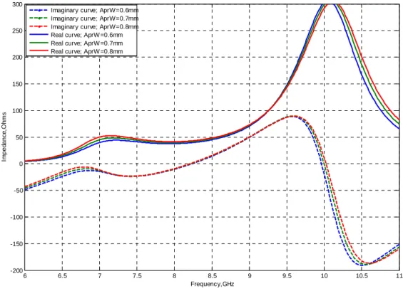
Single port (Port1) parametric analysis
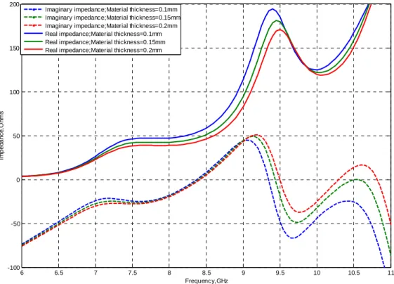
Imaginary impedance; Material thickness = 0.1 mm Imaginary impedance; Material thickness = 0.15 mm Imaginary impedance; Material thickness = 0.2 mm Real impedance; Material thickness = 0.1 mm Real impedance; Material thickness = 0.15 mm Real impedance; Material thickness = 0.2 mm. Imaginary impedance; Material thickness = 0 mm Imaginary impedance; Material thickness = 0.1 mm Imaginary impedance; Material thickness = 0.2 mm Real impedance; Material thickness = 0 mm Real impedance; Material thickness = 0.1 mm Real impedance; Material thickness = 0.2 mm.
Single Port (Port2) parametric analysis
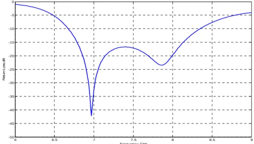
The co-polarization level is 30dB higher than the cross-polarization level in the broad direction. The return loss curve in the presence of adhesive material layer of 0.2mm thickness is presented in Figure 3.32.
Port1&Port2 combined performance with adhesive material
Both xoz(E) and yoz(H) plateau patterns are found to be symmetrical however with -3dB HPBW of 120°. There is a neat symmetry in the xoz and yoz plane radiation patterns with -3dB HPBW for both plane patterns to be 70°.
X band DRA Fabrication & Measurements
Antenna design parameters
Measured results
The port1's radiation patterns in the yoz-(E) plane and xoz-(H) plane are shown in Figure 3.41(a) and (b) respectively. The Port2's radiation patterns in the xoz-(E) plane and yoz-(H) plane are shown in Fig.3.42(a) and (b) respectively.
Performance analysis
Conclusion
After the individual slot loop and DRA performances are optimized, the unified structure is analyzed to observe the appropriate -10 dB total bandwidth and degree of interconnection. Initially, the slot loop design is analyzed and optimized and subjected to free space and phantom model tests.
CPW fed slot loop initial design
Basic performance analysis
Both the E-plane (yoz) and H-plane (xoz) fields exhibit pure symmetry in their broadside shapes, however, the xoz-plane pattern is observed to be narrower compared to the yoz-plane. -3dB Half Power Beam Width (HPBW) for yoz plane is found to be 80° while for xoz plane it is increased to 120°.
DRA loading effect
The (yoz) and (xoz) plane radiation patterns are depicted in Figure 4.11(a) and (b) and it can be observed that the yoz plane pattern is tilted towards 30 angle theta with reference to the broadside direction, while xoz is found to be unaffected and still shows pure symmetry in its shape. The azimuthal radiation patterns are given in Figure 4.12, which shows that due to the increase in its level, Gain theta is now comparable to Gain phi.
CPW fed slot loop final design
Final design analysis
As observed in section (4.1.2), the yoz plane pattern is still narrow compared to the xoz plane, while the -3dB Half Power Beam Width (HPBW) is seen to be unchanged. Table 4.5: Effect of ground plane size on bandwidth, gain, F/B, -3dB (HPBW) beamwidth and antenna efficiency.
On-body performance
The gain is estimated to be 2.3 dBi with 98% radiation efficiency. Cross polarizations in the broad direction are typically -30 dB or better. The gain is estimated to be 6.5 dBi while the radiation efficiency has dropped from 98% to 70%. Cross polarizations in the broad direction are typically -30 dB or better.
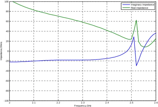
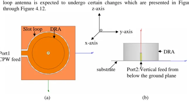
Vertical monopole fed DRA initial design
Evaluation for adhesive material effect
To make the DRA resonate at around 2.2 GHz, the design parameters are given in Table 4.7, while its simulation result is presented in Figure 4.25. Adhesive material layer=0.1mm Adhesive material layer=0.2mm Adhesive material layer=0.3mm Adhesive material layer=0.4mm Adhesive material layer=0.5mm.
Vertical monopole fed DRA final design
Final design analysis
The end-type fire radiation pattern in the elevation plane (yoz & xoz) is shown in Figure 4.29(a) and (b). Both planar models are found to be purely symmetrical with cross polarizations of -12dB or better. The radiation pattern in the azimuthal plane is given in Figure 4.30 where it can be observed that Gain Phi is -20dB less than that of Gain theta.
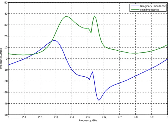
Planar feed tests
The return loss and impedance curves presented in 4.32 and 4.33 illustrate that due to the interception of slot loop the impedance bandwidth and resonance frequency of the DRA is affected. One such situation is presented in 4.36 where the DRA feed line passes under the slot where completely zero fields are seen.
On-body performance
The yoz-plane and xoz-plane radiation patterns are depicted in Figure 4.40(a) and (b) and, as expected, no significant change in the final fire pattern is observed. The azimuth plane radiation patterns presented in figure 4.41 speak of much higher value of Gain theta compared to Gain phi and it presents almost the same situation as in body free case.
Coupling performance
Therefore, it is important to observe their common behavior in the presence of the body. The return loss of the slotted loop, which was found to be more sensitive, remains below the -10 dB level and can be attributed to the presence of the lossy nature of the body with (εr=53 and a loss tangent of 0.002).
Two ports planar feed structure
- Microstrip fed slot loop design
- DRA loading effect
- Interrupted slot loop design performance
- On-body analysis
- Microstrip fed DRA design performance
- On-body analysis
The slot loop radius of 17 mm and width of 1 mm has been found to produce resonance around 2.4 GHz. Due to the need for miniaturization of the antenna structure, the ground plane and substrate dimensions have now been reduced to 36 mm × 36 mm. The slot loop design values in the DRA load context are revised with a slot loop radius of 15.5 mm, width of 0.4 mm, and break distance of 11 mm. On the same basis, the stub length is optimized at 4.5mm.
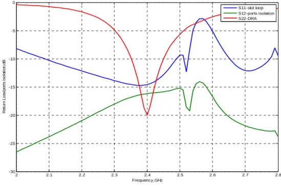
Coupling performance Free space performance
The end-fire type radiation pattern in the (xoz & yoz) elevation levels is depicted in Figure 4.66(a) and (b). The port isolation is found to improve to -15dB. This slight change in results can be attributed to the presence of lossy nature of the phantom body, but the proposed antenna resists such limitations imposed on its performance and shows fidelity to produce the desired results.
Conclusion
The proposed antenna is more compact and conformal with both sources exhibiting planar structure, ideally suited for on-body applications to deliver diversity gain (DG) performance. The performance of BAN antennas is evaluated when used in various channel configurations over the body surface, typically Line Of Sight (LOS) and Non Line Of Sight (NLOS) communication links.
Overview of mobile radio channel
The coherence time "Tc" of the channel accounts for the rapid changes that occur in the propagation environment or the displacement of the mobile unit. If the symbol time "Ts" of the digital transmission is greater than "Tc", the communication is distorted.
BAN channel in indoor environment
Main channel parameters [4]
This function helps to identify the coherence time used and to extract slow and fast fading from the received signal. It represents the average fading time for a given threshold, usually with reference to the RMS value of the signal and it helps to set the sampling time to correctly analyze the signals in BAN.
Statistical channel modelling
Antenna measurements (non planar feeds)
Diversity Gain Analysis
Figure 5.8: Lock loop, DRA and their combined power receiving patterns representing clear power imbalance between the two receiving branches. Figure 5.14: Closed loop, DRA and their combined power receiving patterns representing no power imbalance between the two receiving branches.
Antenna measurements (planar feeds)
Diversity Gain Analysis
Figure 5.22: Closed loop, DRA and their combined power receiving patterns representing clear power imbalance between the two receiving branches. Figure 5.28: Closed loop, DRA and their combined power receiving patterns representing no power imbalance between the two receiving branches.
Conclusion
2] A.A Serra, P.Nepa, G.Manara and P.S Hall "Diversity Measurement for Body Communication Systems" IEEE ANTENNAS AND WIRELESS CONNECTIONS LETTERS, VOL. 5] T.Alves, B.Poussot and J.M.Laheurte “PIFA peak loaded monopole antenna with diversity features for WBAN applications” IEEE ANTENNAS AND WIRELESS CONNECTIONS LETTERS, Volume 10, 2011, Pages 693-696.
Overall conclusion
Slot loop and DRA branches have been successfully integrated to provide extensive and ultimate types of radiation patterns. Both of these diversity antennas offer good gate isolation (-14dB) and feature dual radiation patterns.
Future prospects
The second diversity antenna offers narrower common impedance bandwidth (1.5%) with broadside radiation pattern slightly asymmetrical and end-fire radiation pattern purely symmetrical. The size of the DRA as part of the diversity antenna has a great potential to be reduced.
List of Journal publications
Evaluation of Adhesive Material’s Role in DRA Fabrications
For the 8.9 GHz antenna, in the case of the monopole excitation the measured resonance frequency shifted upwards to 9.25 GHz instead of calculated one at 8.9 GHz together with an increase in its impedance bandwidth from 17% to 20%. In the 2.4 GHz antenna, the diaphragm feeding effect was found to be more robust (6.2%) than the monopole feeding (2%).

Résumé en Français
L'analyse de l'antenne DRA en bande X montre des performances similaires sur les deux ports (appelés port 1 et port 2). Par conséquent, la bande passante partagée par les deux accès est limitée à environ 2,4 GHz par la bande passante de l'antenne DRA.