HAL Id: inria-00539718
https://hal.inria.fr/inria-00539718v1
Submitted on 25 Nov 2010 (v1), last revised 6 Jan 2011 (v2)
HAL is a multi-disciplinary open access archive for the deposit and dissemination of sci- entific research documents, whether they are pub- lished or not. The documents may come from
L’archive ouverte pluridisciplinaire HAL, est destinée au dépôt et à la diffusion de documents scientifiques de niveau recherche, publiés ou non, émanant des établissements d’enseignement et de
EdiFlow: data-intensive interactive workflows for visual analytics
Véronique Benzaken, Jean-Daniel Fekete, Wael Khemiri, Ioana Manolescu
To cite this version:
Véronique Benzaken, Jean-Daniel Fekete, Wael Khemiri, Ioana Manolescu. EdiFlow: data-intensive interactive workflows for visual analytics. Journées Bases de Données Avancées, Oct 2010, Toulouse, France. �inria-00539718v1�
EdiFlow: data-intensive interactive workflows for visual analytics
V´eronique Benzaken
2Jean-Daniel Fekete
1Wael Khemiri
1,2Ioana Manolescu
1,21INRIA Saclay–ˆIle-de-France,firstname.lastname@inria.fr
2LRI, Universit´e de Paris Sud-11,firstname.lastname@lri.fr
Abstract
La visualisation analytique (visual analytics) vise `a combiner la visualisation des donn´ees avec des tˆaches d’analyse et de fouille. Etant donn´ee la complexit´e et la volum´etrie importante des donn´ees scientifiques (par exemple, les donn´ees associ´ees
`a des processus biologiques ou physiques, donn´ees des r´eseaux sociaux, etc.), la visualisation analytique est appel´ee `a jouer un rˆole important dans la gestion des donn´ees scientifiques.
La plupart des plates-formes de visualisation analytique actuelles utilisent des m´ecanismes m´emoire pour le stockage et le traitement des donn´ees, ce qui limite le volume de donn´ees trait´ees. En outre, l’int´egration de nouveaux algorithmes dans le processus de traitement n´ecessite du code d’int´egration ad-hoc. Enfin, les plate- formes de visualisation actuelles ne permettent pas de d´efinir et de d´eployer des processus structur´es, o`u les utilisateurs partagent les donn´ees et, ´eventuellement, les visualisations.
Ce travail, issu d’une collaboration entre des chercheurs en visualisation ana- lytique interactive et en bases de donn´ees, appporte deux contributions. (i) Nous proposons une architecture g´en´erique pour d´eployer une plate-forme de visual an- alyticsau-dessus d’un syst`eme de gestion de bases de donn´ees (SGBD). (ii) Nous montrons comment propager les changements des donn´ees dans le SGBD, au travers des processus et des visualisations qui en font partie. Notre approche a ´et´e implant´ee dans un prototype appell´e EdiFlow, et valid´ee `a travers plusieurs applications. Elle pourrait aussi s’int´egrer dans une plate-forme de workflow scientifique `a usage in- tensif de donn´ees, afin d’en augmenter les fonctionnalit´es de visualisation.
Mots-cl´e : visualisation analytique des donn´ees, workflow scientifique
1 Introduction
The increasing amounts of electronic data of all forms, produced by humans (e.g., Web pages, structured content such as Wikipedia or the blogosphere) and automatic tools (log- gers, sensors, Web services, scientific programs or analysis tools) lead to a situation of unprecedented potential for extracting new knowledge, finding new correlations, and in- terpreting data. Visual analytics is a new branch of the information visualization / human- computer interaction field [17]. Its aim is to enable users to closely interact with vast amounts of data using visual tools. Thanks to these tools, a human may detect phenom- ena or trigger detailed analysis which may not have been identifiable by automated tools alone.
Though, most current visual analytics tools have some conceptual drawbacks. Indeed, they rarely rely on persistent databases (with the exception of [7]). Instead, the data is loaded from files or databases and is manipulated directly in memory because smooth vi- sual interaction requires redisplaying the manipulated data 10-25 times per second. Stan- dard database technologies do not support continuous queries at this rate; at the same time, ad-hoc in-memory handling of classical database tasks (e.g., querying, sorting) has obvious limitations. Based on our long-standing experience developing information visu- alisation tools [9] [1], we argue connecting a visual analysis tool to a persistent database management system (DBMS) has many benefits:
• Scalability: larger data volumes can be handled based on a persistent DBMS
• Persistence and distribution: several users (possibly on remote sites) can interact with a persistent database, whereas this is not easily achieved with memory-resident data structures. Observe that users may need to share not only raw data, but also visualizations built on top of this data. A visualization can be seen as an assign- ment of visual attributes (e.g., X and Y coordinates, color, size) to a given set of data items. Computing the value of the visual attributes may be expensive, and/or the choice of the visualized items may encapsulate human expertise. Therefore, visualizations have high added value and it must be easy to store and share them, e.g., allowing one user to modify a visualization that another user has produced.
• Data management capabilities provided by the database: complex data processing tasks can be coded in SQL and/or some imperative scripting language. Observe that such data processing tasks can also include user-defined functions (UDFs) for computations implemented outside the database server. These functions are not stored procedures managed by the database (e.g., Java Stored Procedure). These are executable programs external to the database.
The integration of a DBMS in a visualisation platform must take into account the follow- ing prevalent aspects in today’s visual analytics applications:
• Convergence of visual analytics and workflow: current visual analytics tools are not based on workflow (process) models. This fits some applications where datasets and
tasks are always exploratory and different from one session to the next. Several vi- sual analytics applications however, require a recurring process, well supported by a workflow system. The data processing tasks need to be organized in a sequence or in a loop; users with different roles may need to collaborate in some application before continuing the analysis. It also may be necessary to log and allow inspect- ing the advancement of each execution of the application. (Scientific) workflows platforms allow such automation of data processing tasks. They typically combine database-style processing (e.g., queries and updates) with the invocation of external functions, implementing complex domain-dependent computations. Well-known scientific workflow platforms include Kepler [3], or Trident [18]. These systems build on the experience of the data and workflow management communities; they could also benefit from a principled way of integrating powerful visualisation tech- niques.
• Handling dynamic data and change propagation: an important class of visual an- alytics applications has to deal with dynamic data, which is continuously updated (e.g., by receiving new additions) while the analysis process is running; conversely, processes (or visualisation) may update the data. The possible interactions between all these updates must be carefully thought out, in order to support efficient and flexible applications.
Our work addresses the questions raised by the integration of a DBMS in a visual analytics platform. Our contributions are the following:
1. We present a generic architecture for integrating a visual analytics tool and a DBMS.
The integration is based on a core data model, providing support for (i) visualisations, (ii) declaratively-specified, automatically-deployed workflows, and (iii) incremental prop- agation of data updates through complex processes, based on a high-level specification.
This model draws from the existing experience in managing data-intensive workflows [2, 6, 16].
2. We present a simple yet efficient protocol for swiftly propagating changes between the DBMS and the visual analytics application. This protocol is crucial for the architecture to be feasible. Indeed, the high latency of a ”vanilla” DBMS connection is why today’s visual analytics platforms do not already use DBMSs.
3. We have fully implemented our approach in a bare-bones prototype called EdiFlow, and de facto ported the InfoVis visual analytics toolkit [9] on top of a standard Oracle server. We validate the interest of our approach by means of three applications.
This article is organized as follows. Section 2 compares our approach with related works. Section 3 describes three applications encountered in different contexts, illustrat- ing the problems addressed in this work. Section 4 presents our proposed data model, while the process model is described in Section 5. We describe our integration architec- ture in Section 6, discuss some aspects of its implementation in our EdiFlow platform, we then conclude in Section 8.
2 Related work
Significant research and development efforts have resulted in models and platforms for workflow specification and deployment. Recently,scientific workflowplatforms have re- ceived significant attention. Different from regular (business-oriented) workflows, sci- entific workflows notably incorporate data analysis programs (or scientific computations more generally) as a native ingredient.
One of the first integration of scientific workflows with DBMSs was supported by [2].
Among the most recent and well-developed scientific workflow projects, Kepler [3] is designed to help scientists, analysts, and computer programmers to create, execute, and share models and analyses across a broad range of scientific and engineering disciplines.
Kepler provides a GUI which helps users to select and then connect analytical components and data sources to create a scientific workflow. In this graphical representation, the nodes in the graph represent actors and the vertices are links between the actors.
SciRun [11] is a Problem Solving Environment, for modeling, simulation and visu- alization of scientific problems. It is designed to allow scientists to interactively control scientific simulations while the computation is running. SCIRun was originally targeted at computational medicine but has, later, been expanded to support other scientific domains.
The SCIRun environment provides a visual interface for dataflow network’s construction.
As the system will allow parameters to be changed at runtime, experimentation is a key concept in SCIRun. As soon as a parameter is updated, at runtime, changes will propa- gated through the system and a re-evaluation induced.
GPFlow [15] is a workflow platform providing an intuitive web based environment for scientists. The workflow model is inspired by spreadsheets. The workflow environ- ment ensures interactivity and isolation between the calculation components and the user interface. This enables workflows to be browsed, interacted with, left and returned to, as well as started and stopped.
VisTrails [4] combines features of both workflow systems and visualization fields.
Its main feature is to efficiently manage exploratory activities. The user interaction in VisTrails is performed by iteratively refining computational tasks and formulating test hypotheses. VisTrails maintains detailed provenance of the exploration process. Users are able to return to previous versions of a dataflow and compare their results. However, VisTrails is not meant to manage dynamic data. In VisTrails, dynamicity is performed by allowing users to change some attributes in order to compare visualization results.
It does not include any model to handle data changes. Indeed, when the user starts its workflow process, VisTrails does not take into account the updated data in activities that have already started: there is no guarantee that the model for updates is correct.
Trident [18] is a scientific workflow workbench built on top of a commercial workflow system. It is developed by Microsoft corporation to facilitate scientific workflows man- agement. Provenance in Trident is ensured using a publication/subscription mechanism called the Blackboard. This mechanism allows also for reporting and visualizing inter- mediate data resulting from a running workflow. One of the salient features of Trident is to allow users to dynamically select where to store results (on SQL Server for example)
issued by a given workflow. However, it does not support dynamic data sources nor does it integrate mechanisms to handle such data.
Orchestra [13] addresses the challenge of mapping databases which have potentially different schemas and interfaces. Orchestra is specially focusing on bioinformatics ap- plications. In this domain, one find many databases containing overlapping informations with different level of quality, accuracy and confidence. Database owners want to store a relevant (”alive”)version of relevant data. Biologists would like to download and main- tain local ”live snapshots” of data to run their experiments. The Orchestra system focus on reconciliation across schemas. It is a fully peer-to-peer architecture in which each participant site specifies which data it trusts in. The system allows all the sites to be continuously updated, and on demand, it will propagate these updates across sites. User interaction in Orchestra is only defined at the first level using trust conditions. Moreover, the deployed mechanism is not reactive. Indeed, there is no restorative functions called after each insert/update operation.
Several systems were conceived to create scientific workflows using a graphical inter- face and enabling data mining tasks (e.g., Knime [5], Weka [10]). However, none of these systems includes a repair mechanism to support the change in data sources during a task or process execution.
To summarize, all these platforms share some important features, which we also base our work on. Workflows aredeclaratively specified, data-intensiveand (generally)multi- user. They include querying and updating data residing in some form of a database (or in less structured sources). Crucial for their role is the ability to invoke external procedures, viewed as black boxes from the workflow engine perspective. The procedures are implemented in languages such as C, C++, Matlab, Fortran. They perform important domain-dependent tasks; procedures may take as input and/or produce as output large collections of data. Finally, current scientific workflow platforms do provide, or can be coupled with, somevisualisationtools, e.g., basic spreadsheet-based graphics, map tools.
With respect to these platforms, our work makes two contributions: (i) we show how a generic data visualisation toolkit can be integrated as afirst-class citizen; (ii) we present a principled way of managing updatesto the underlying sources, throughout the enactment of complex processes. This problem is raised by the high data dynamicity intrinsic to visual analytics applications. However, the scope of its potential applications is more general, as long-running scientific processes may have to handle data updates, too.None of these platforms are currently able to propagate data changes to a running process. The process model we propose could be integrated, with some modest programming effort, in such platforms, hence offering complementary functionalities to their existing ones.
Most of existing interactive platforms for data visualization [9] [1] focus on the inter- action between the human expert and a data set consisting of a completely known set of values. They do not ease the inclusion of data analysis programs on the data. Moreover, as previously explained, they do not support the definition of structured processes, nor (by absence of an underlying DBMS) do they support persistence and sharing.
Unlike current data visualisation platforms, our work provides a useful coupling to DBMSs, providing persistent storage, scalability, and process support. Our goal is to
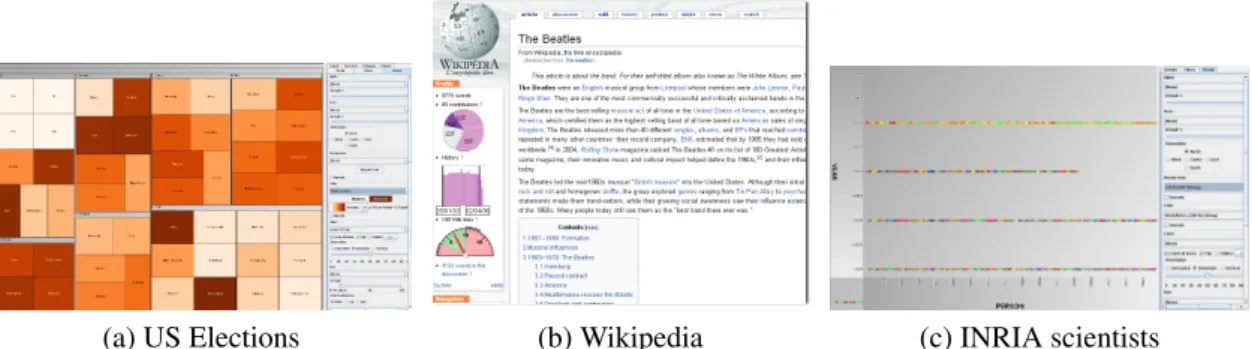
(a) US Elections (b) Wikipedia (c) INRIA scientists
Figure 1: Data visualizations examples.
drastically reduce the programming effort actually required by each new visual analytics application, while enabling them to scale up to very large data volumes. In this work, we present an architecture implementing a repair mechanism, to propagate data source changes to an executing process.
3 Use cases
The following applications illustrate the data processing and analysis tasks which this work seeks to simplify.
US Elections This application aims at providing a dynamic visualisation of elections outcome, varying as new election results become available. The database contains, for each state, information such as the party which won the State during the last three elec- tions. On the voting day, the database gradually fills with new data. This very simple example uses a process of two activities: computing some aggregates over the votes, and visualizing the results. Upon starting, a TreeMap visualisation is computed over the database (distinguishing the areas where not enough data is available yet), as shown on the left up corner in Figure 1. The user can choose a party, then the 51 states are shown with varying color shades. The more the states vote for the respective party, the darker the color. When new vote results arrive, the corresponding aggregated values are recomputed, and the visualisation is automatically updated.
Wikipedia The goal of the application is to propose to Wikipedia readers and contribu- tors some measures related to the history of an article. e.g., how many authors contributed to an article? How did a page evolve over time? The metrics are produced and visualized by the application, whereas the (current) Wikipedia page is displayed directly from the original site, as shown at the center in Figure 1. This application can be decomposed in four elementary tasks: (i) compute the differences between successive versions of each article; (ii) compute a contribution table, storing at each character index, the identifier of the user who entered it; (iii) for each article, compute the number of distinct effec-
tive contributors; and (iv) compute the total contribution (over all contribution tables) of each user. All these computations’ results must be continuously updated to reflect the continuous changes in the underlying data. A total recomputation of the aggregation is out of reach, because change frequency is too high (10 edits per second on average for the French Wikipedia, containing about 1 million pages). Moreover, updates received at a given moment only affect a tiny part of the database. Thus, the Wikipedia application requires: a DBMS for storing huge amounts of data; a well-defined process model includ- ing ad-hoc procedures for computing the metrics of interest; incremental re-computations;
and appropriate visualisations.
INRIA activity reports We have been involved in the development of an application seeking to compute a global view of INRIA researchers by analysing some statistics. The data are collected from Raweb (INRIA’s legacy collection of activity reports available at http://ralyx.inria.fr). These data include informations about INRIA teams, scientists, pub- lications and research centres. Our goal was to build a self-maintained application which, once deployed, would automatically and incrementally re-compute statistics, as needed.
To that end, we first created a database out of all the reports for the years 2005 to 2008.
Simple statistics were then be computed by means of SQL queries: age, team, research center distribution of INRIA’s employees. They were further visualised as shown in Fig- ure 1. Other aggregates were computed relying on external code such as the similarity between two people referenced in the reports in order to determine whether an employee is already present in the database or needs to be added.
All these applications feature data- and computation-centric processes which must react to data changes while they are running and need visual data exploration. The Wikipedia application is the most challenging, by the size of the database, the complexity of its metrics, and the high frequency of updates requiring recomputations.
4 Data model
In this Section, we describe our conceptual data model in Section 4.1, and its concrete implementation in a relational database in Section 4.2.
4.1 Conceptual data model
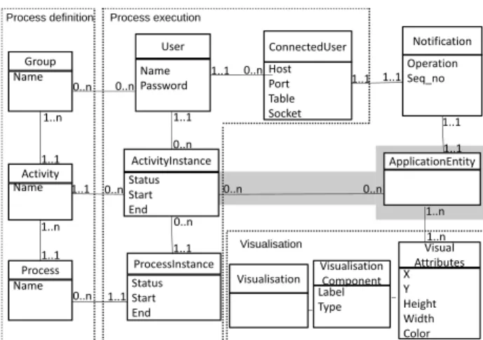
The conceptual data model of visual analytics application is depicted in Figure 2. For readability, the entities and relationships are organized in several groups.
The first group contains a set of entities capturing process definitions. A process consists of some activities. An activity must be performed by a different group of users (one can also see a group as a role to be played within the process). The process’ control flow is not reflected in the data model, but in the separated process model (see Section 5).
An activity instance has a start date and an end date, as well as astatusflag which can take the values: not started (the activity instance is created, e.g. by a user who assigns it to
Status
ActivityInstance ApplicationEntity
0..n 1..1 0..n 1..1
Activity
Name Password
User
Host Port Table Socket ConnectedUser
Operation Seq_no
Notification
1..1 1..1
0..n 1..1
Name Group
0..n
Process execution Process definition
1..1
1..n 1..1
Status Start End
ProcessInstance Status Start End
X Y Height Width Color
Visual Attributes
0..n 1..1 1..1 1..n
1..1 0..n
Name Process Name
Activity
0..n 1..1
0..n 1..n 1..n 0..n
Label Type
Visualisation Component Visualisation
Visualisation
Figure 2: Entity-relationship data model for EdiFlow.
another for completion, but work on the activity has not started yet),running(the activity instance has started but it has not finished) andcompleted(once the activity instance has finished executing. The status of a process instance can take similar values.
Entities in the second group allow recordingprocess execution. Individual users may belong to one or several groups. A user may perform some activity instances, and thus participate to specific process instances. AConnectedUserpairs a user with the host and port from which the user connects at a given time. This information is needed to propagate to a potentially remote visualisation component (running on the remote user’s desktop) updates received while the process is running, as will be discussed in Section 6.
The gray area can be seen as a meta-model, which has to be instantiated in any con- crete application with one or several entities and relationships reflecting the application.
For instance, in the Wikipedia application, one would use the entitiesArticle, User, and Version, with relationships stating that each version of an article is produced by one update of the article by one user etc. Black-box functions, such as e.g. Wikipedia user clustering functions, must also be captured by this application-dependent part of the data model. In the most general case, one may wish to be able to trace the history of a given application data instance, e.g., identify the activity instance which created it, updated it etc. To that purpose, specific customized relationships of the formcreatedBy,validatedByetc. can be defined in the conceptual model. They are represented in Figure 2 by the relationship on a gray background betweenApplicationEntityandActivityInstance.
The third group of entities is used to model visualization. AVisualizationconsists of one or moreVisualisationComponents. Each component offers an individual perspective over a set of entity instances. For example, in Figure 1(b), three visualisation components are shown in the bar at the left of the article, making up a given visualization associated to the article’s edit history. Components of a same visualisation correspond to different ways of rendering the same objects. In each visualisation component, a specific set of VisualAttributesspecify how each object should be rendered. Common visual attributes include(x, y)coordinates, width, height, color, label (a string), whether the data instance
is currently selected by a given visualization component (which typically triggers the recomputation of the other components to reflect the selection, etc).
Finally, theNotificationentity is used to speedily propagate updates to the application entities in various places within a running process. A notification is associated to one or more instances of a particular application entity. It refers to an update performed at a specific moment indicated by theseq notimestamp, and indicates the kind of the update (insert/delete/modify).
4.2 Concrete data model
We assume a simplerelationalenactment of this conceptual model. We have considered XML but settled for relations since performant visualisation algorithms are already based on a tabular model [9]. Thus, a relation is created for each entity, endowed with a primary key; relationships are captured by means of association tables with the usual foreign key mechanism. By issuing a query to the database, one can determine ”which are the com- pleted activity instances in processP”, or ”which is theRtuple currently selected by the user from the visualization componentV C1”.
We distinguish two kinds of relations. DBMS-hosted relations are by definition per- sistent inside a database server and their content is still available after the completion of all processes. Such relations can be used in different instances, possibly of different processes. In contrast, temporary relations are memory-resident, local to a give process instance (their data is not visible and cannot be shared across process instances), and their lifespan is restricted to that of the process instance which uses them. If temporary relation data is to persist, it can be explicitly copied into persistent DBMS tables, as we explain shortly below.
5 Process model
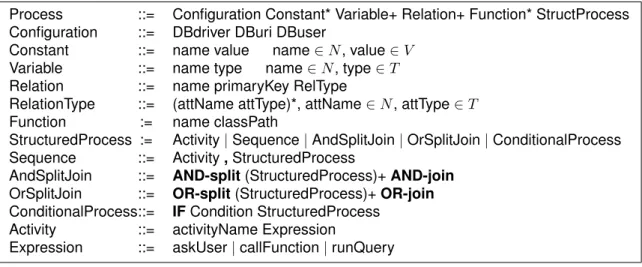
We consider a process model inspired by the basic Workflow Management Coalition model. Figure 3 outlines (in a regular expression notation) the syntax of our processes.
We use a set of variables, constants and attribute namesN, a set of atomic valuesV, and a set of atomic data typesT; terminal symbols used in the process structure are shown in boldface. The main innovative ingredient here is the treatment ofdata dynamics, i.e., the possibility to control which changes in the data are propagated to which part(s) of which process instances. We now describe the process model in detail.
Relations and queries. A process is built on top of a set of relations implementing the data model. Relations are denoted by capital letters such as R, S, T, possibly with subscripts. A query is a relational algebraic expression over the relations. We consider as operators: selection, projection, and cartesian product. Queries are typically designated by the letterQpossibly with subscripts.
Variables. A variable is a pair composed of a name, and of an (atomic) value. Vari- ables come in handy for modelling useful constants, such as, for example, a numerical
Process ::= Configuration Constant* Variable+ Relation+ Function* StructProcess Configuration ::= DBdriver DBuri DBuser
Constant ::= name value name∈N, value∈V Variable ::= name type name∈N, type∈T Relation ::= name primaryKey RelType
RelationType ::= (attName attType)*, attName∈N, attType∈T Function := name classPath
StructuredProcess := Activity|Sequence|AndSplitJoin|OrSplitJoin|ConditionalProcess Sequence ::= Activity,StructuredProcess
AndSplitJoin ::= AND-split(StructuredProcess)+AND-join OrSplitJoin ::= OR-split(StructuredProcess)+OR-join ConditionalProcess::= IFCondition StructuredProcess
Activity ::= activityName Expression
Expression ::= askUser|callFunction|runQuery
Figure 3: XML schema for the process model.
threshold for a clustering algorithm. Variables will be denoted by lower-case letters such asv, x, y.
Procedures.A procedure is a computation unit implemented by some external, black- box software. A typical example is the code computing values of the visual attributes to be used in a visualisation component. Other examples include e.g., clustering algorithms, statistical analysis tools.
A procedure takes as inputl relationsR1, R2, . . . , Rlwhich are read but not changed andm relationsT1w, T2w, . . . , Tmw which the procedure may readandchange, and outputs data innrelations:
p:R1, R2, . . . , Rl, T1w, T2w, . . . , Tmw →S1, S2, . . . , Sn
We considerpas a black box, corresponding to software developed outside the database engine, and outside of EdiFlow by means of some program expressed e.g., in C++, Java, MatLab. Functions are processes with no side effects (m = 0).
Delta handlers. Associated to a procedure may beprocedure delta handlers. Given some update (or delta) to a procedure input relation, the delta handler associated to the procedure may be invoked to propagate the update to a process. Two cases can be envi- sioned:
1. Update propagation is needed while the procedure is being executed. Such is the case for instance of procedures which compute point coordinates on a screen, and must update the display to reflect the new data.
2. Updates must be propagated after the procedure has finished executing. This is the case for instance when the procedure performs some quantitative analysis of which only the final result matters, and such that it can be adjusted subsequently to take into account the deltas.
The designer can specify one or both of these handlers. Formally, each handler is a procedure in itself, with a table signature identical to the main procedure. The convention is that if there are deltas only for some ofp’s inputs, the handler will be invoked providing
empty relations for the other inputs. With respect to notations, ph,r is the handler of p to be used while p is running, and ph,f is the handler to be used after p finished. Just like other procedures, the implementation of handlers is opaque to the process execution framework. This framework, however, allows one to recuperate the result of a handler invocation and inject it further into the process, as we shall see.
Distributive procedures. An interesting family of procedures are those which dis- tribute over union in all their inputs. More formally, letX be one of theRi inputs ofp, and let∆Xbe the set of tuples added toX. Ifpis distributive then:
p(R1, . . . , X∪∆X, . . . , Tmw)=p(R1, . . . , X, . . . , Tmw)∪p(R1, . . . ,∆X, . . . , Tmw) There is no need to specify delta handlers for procedures which distribute over the union, since the procedure itself can serve as handler.
Expressions. We use a simple language for expressions, based on queries and proce- dures. More formally:
e::= Q| p(e1, e2, . . . , en, T1w, T2w, . . . , Tpw).tj,1≤j ≤m
The simplest expressions are queries. More complex expressions can be obtained by call- ing a procedurep, and retaining only itsj-th output table. Ifpchanges some of its input table, evaluating the expression may have side effects. If the side effects are not desired, pcan be invoked by giving it some new empty tables, which can be memory-resident, and will be silently discarded at the end of the process. Observe that the firstn invocation parameters are expressions themselves. This allows nesting complex expressions.
Activities. We are now ready to explain the building blocks of our processes, namely activities.
a ::=v ←α | upd(R) | (S1, S2, . . . , Sn)←p(e1, e2, . . . , en, T1w, T2w, . . . , Tnw) Among the simplest activities arevariable assignmentsof the formv ← α. Another simple activity is a declarative update of a tableR, denotedupd(R). Unlike the table mod- ifications that an opaque procedure may apply, these updates are specified by a declarative SQL statement. Finally, an activity may consist of invoking a procedurepby providing appropriate input parameters, and retaining the outputs in a set of tables.
Visualisationactivities must be modelled as procedures, given that their code cannot be expressed by queries.
Processes. A process description can be modelled by the following grammar:
P ::= | a, P | PkP | P ∨P | e?P
In the above, a stands for an activity. A process is either the empty process (), or asequenceof an activity followed by a process (,), or aparallel (and) split-join of two processes (k), or anor split-joinof two processes (with the semantics that once a branch is triggered, the other is invalidated and can no longer be triggered). Finally, a process can consist of aconditional blockwhere an expressione(details below) is evaluated and if this yields true, the corresponding process is executed.
Reactive processes. Areactive processcan now be defined as a 5-tuple consisting of a set of relations, a set of variables, a set of procedures, a process and a set of update propagations. More formally:
RP ::=R∗, v∗, p∗, P, U P∗
Anupdate propagation U P specifies what should be done when a set of tuples, denoted
∆R, are added to an application-dependent relation R, say, att∆R. Several options are possible. We discuss them in turn, and illustrate with examples.
1. Ignore∆R for the execution of all processes which had started executing beforet∆R. The data will be added toR, but will only be visible forprocess instances having started aftert∆R. This recalls locking at process instance granularity, where each process oper- ates on exactly the data which was available when the process started. We consider this to be the default behaviour for all updates to the relations part of the application data model.
Use case: A social scientist applies a sequence of semi-automated partitioning and clustering steps to a set of Wikipedia pages. Then, the scientist visualises the outcome.
In this case, propagating new items to the visualisation would be disruptive to the user, which would have to interrupt her current work to help apply the previous steps to the new data.
2.Ignore∆Rfor the execution of allactivitieswhich had started executing (whether they are finished or not) beforet∆R. However, for a process already started, instances of a specific activity which start aftert∆Rmay also use this data.
Use case: The social scientist working on a Wikipedia fragment first has to confirm personal information, give some search criteria for the pages to be used in this process.
Then, she must interact with a visualisation of the chosen pages. For this activity, it is desirable to provide the user with the freshest possible snapshot, therefore additions between the beginning of the process instance, and the moment when the user starts the last activity, should be propagated.
3. As a macro over the previous option and the process structure, one could wish for
∆R to be propagated toinstances of all activities that are yet to be started in a running process.
Use case: Intuitively, data should not ”disappear” during the execution of a process instance (unless explicitly deleted). In the previous use case, if we add an extra activity at the end of the process, that activity would typically expect to see the whole result of the previous one.
4. Propagate the update∆R toall the terminated instances of a given activity. We can moreover specialize the behavior on whether we consider only activity instances whose process instances have terminated, only activity instances whoseprocess instances are still running, or both.
Use case: We consider a process whose first activities are automatic processing steps, e.g., computingdiffs between the old and the new version of a Wikipedia page, updating a user’s contribution, the page history etc. The last activity is a visualisation one where the scientist should be shown fresh data. Typically, the visualisation activity will last
DBMS
Application,workflow and vis. data EdiFlow
Users
External updates
Modules Visualisation module 1
Visualisation module 2
Visualisation module 3
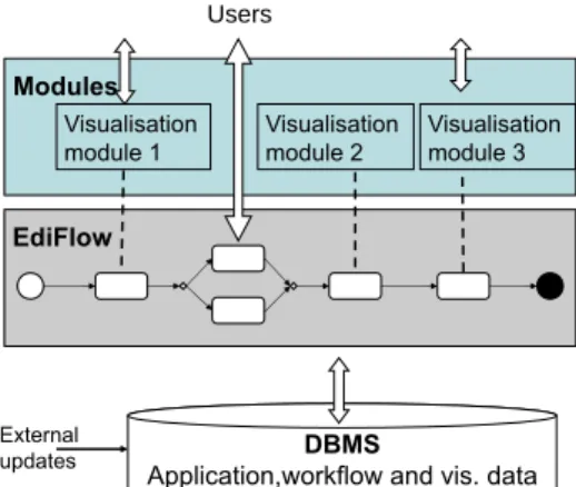
Figure 4: EdiFlow architecture.
for a while, and it may refresh itself at intervals, to reflect the new data. In this case, it makes sense to apply the automated processing activities to the new pages received while running the process instance, even after the respective activities have finished.
5. Propagate the update∆R to all the running instances of a given activity, whether they had started beforet∆Ror not.
Use case: This may be used to propagate newly arrived tuples to all running instances of a visualisation activity, to keep them up-to-date.
Formally then, an update propagation action can be described as:
U P ::= R, a,((’ta’,(’rp’|’tp’))|’ra’|(’fa’,’rp’))
whereRis a relation andais an activity. An update propagation action describes a set of instances of activitya, to which the update∆Rmust be propagated. The possible combi- nations of terminal symbols designate:
[ta rp:]terminatedactivity instances part ofrunning processes;
[ta tp:]terminatedactivity instances part ofterminated processes;
[ra: ] runningactivity instances (obviously, part of running processes);
[fa rp:]futureactivity instances part ofrunningprocesses.
It is possible to specify more than one compensation action for a givenRand a given activitya. For instance, one may write: (R, a, ’ra’), (R, a, ’fa’, ’rp’).
For simplicity, the syntax above does not model the macro possibility numbered 3 in our list of options. One can easily imagine a syntax which will then be compiled into U P’s as above, based on the structure ofP.
6 An architecture for reactive processes
Our proposed architecture is depicted in Figure 4. The workflow management logic runs on top of the DBMS; visualisation software is integrated under the form of modules. Pro-
cesses are specified in a high-level syntax following the structure described in Section 5.
The enactment of a process thus specified consists of adding the necessary tuples to the Process and Activity relations. During process executions, the necessary data manipula- tion statements are issued to (i) record in the database the advancement of process and activity instances, (ii) evaluate on the database queries and updates, allow external pro- cedures to read and update the application-driven entities and (iii) record the connections between users and application instances, and application data.
In the sequel, Section 6.1 shows how to implement various degrees of isolation be- tween concurrent processes operating on top of the same database. Section 6.2 outlines update propagation. Section 6.3 considers an important performance issue: efficient syn- chronization between memory-resident tables, that visualisation uses, and disk-resident tables.
6.1 Isolation
Applications may require different levels of sharing (or, conversely, of isolation) among concurrent activities and processes.
Process- and activity-based isolationLeta1 be an instance of activitya, such thata1 is part of a process instancep1. By default, queries evaluated during the execution of p carry over the whole relations implementing the application-specific data model. LetR be such a relation.
It may be the case that a1 should only see theR tuples created as part of executing p1. For instance, when uploading an experimental data set, a scientist only sees the data concerned by that upload, not the data previously uploaded by her and others. Such isolation is easily enforced using relationships between the application relations and the ActivityInstancetable (recall Figure 2 in Section 4). A query fetching data fromR fora1 should select only theRtuples created byp1, the process to whicha1belongs, etc. These mechanisms are fairly standard.
Time-based isolation As discussed in Section 5, the data visible to a given activity or process instance may depend on the starting time of that instance. To enable such comparisons, we associate to each application tableRacreation timestamp, which is the moment when eachRtuple entered the database (due to some process or external update).
Rtuples can then be filtered by their creation date.
Isolating process instances from tuple deletions requires a different solution. If the process instancep3erases some tuples fromR, one may want to prevent the deleted tuples from suddenly disappearing from the view of another running process instance, sayp4. To prevent this, tuples are not actually deleted fromRuntil the end ofp3’s execution. We denote that moment byp3.end. Rather, the tuples are added to adeletion tableR−. This table holds tuples of the form(tid, tdel, pid,⊥), wheretidis the deletedRtuple identifier, tdelthe deletion timestamp,pidthe identifier of the process deleting the tuple. The fourth attribute will take the valuep3.endat the end ofp3. To allowp3 to run as if the deletion occurs, EdiFlow rewrites queries of the formselect * from Rimplementing activities of p3 with:
select * from R where tid not in (select tid from R−where pid=p3)
Whenp3 terminates, if no other running process instance uses table R1, then we delete fromRandR−the tuplesσpid=p3(R−). Otherwise,RandR−are left unchanged, waiting for the other R users to finish. However, a process instance started after t0 > p3.end should not see tuples inR−deleted byp3, nor by any other process whose end timestamp is smaller thant0. In such a recently-started process, a query of the formselect * from R is rewritten by EdiFlow as:
select * from R where tid not in (select tid from R−where processend< t0)
We still have to ensure that deleted tuples are indeed eventually deleted. After the check performed at the end ofp3, Ediflow knows that some deletions are waiting, inR−, for the end of a process instances started beforep3.end. We denote these process instances by waitR,p3. Afterp3.end, whenever a process inwaitR,p3 terminates, we eliminate it from waitR,p3. When the set is empty, the tuplesσpid=p3(R−)are deleted fromRandR−.
6.2 Update propagation
We now discuss the implementation of the update propagation actions described in Sec- tion 5. EdiFlow compiles theU P (update propagation) statements into statement-level triggers which it installs in the underlying DBMS. The trigger calls EdiFlow routines implementing the desired behavior, depending on the type of the activity (Section 5), as follows. Variable assignments are unaffected by updates. Propagating an update∆Ri to relationRi to a query expression leads to incrementally updating the query, using well- known incremental view maintenance algorithms [12]. Propagating an update to an ac- tivity involving a procedure call requires first, updating the input expressions, and then, calling the corresponding delta handler.
6.3 Synchronizing disk-resident and in-memory tables
The mechanisms described above propagate changes to (queries or expression over) ta- bles residing in the SQL DBMS. However, the visualisation software running within an instance of a visualisation activity needs to maintain portions of a table in memory, to refresh the visualisation fast. A protocol is then needed to efficiently propagate updates made to a disk-resident table, call itRD, to its possibly partial memory image, call itRM. Conversely, when the visualisation allows the user to modifyRM, these changes must be propagated back toRD. Observe thatRM exists on the client side and therefore may be on a different host thanRD.
To that end, we install CREATE, UPDATE and DELETE triggers monitoring changes to the persistent tableRD. Whenever one such change happens, the corresponding trigger adds to the Notification table stored in the database (recall the data model in Figure 2) one
1The definition of a process explicitly lists the tables it uses, and from the process, one may retrieve the process instances and check their status (Figure 2).
tuple of the form (seq no, ts, tn, op), whereseq nois a sequential number,tsis the update timestamp,tnis the table name andopis the operation performed. Then, a notification is sent toRM that ”there is an update”. Smooth interaction with a visualization component requires that notifications be processed very fast, therefore we keep them very compact and transmit no more information than the above. A notification is sent via a socket connected to the process instance holdingRM. Information about the host and port where this process runs can be found in the Client table (Figure 2). When the visualisation software decides to process the updates, it reads them from the Notification table, starting from its last readseq novalue.
The synchronization protocol betweenRM andRD can be summarized as:
1. A memory object is created in the memory of the Java process (RM);
2. It asks a connection manager to create a connection with the database;
3. The connection manager creates a network port on the local machine and associates locally a quadruplet toRM: (db, RD, ip, port);
4. The quadruplet is sent to the DB to create an entry in its ConnectedUser table;
5. The DB connects to the client using the IP/PORT and expects a hellomessage to check that it is the right protocol;
6. The connection manager accepts the connection, sends thehellomessage and ex- pects a REPLY message to check that it is the expected protocol too;
7. When the RD is modified, the database trigger sends a notif y message with the table name as parameter to theRM (through theip/portaddress);
8. When it receives the notification, the visualisation software holdingRM connects to the SQL server and queries the created/updated/deleted list of rows. It can update them at any time it wants;
9. WhenRM is modified, it propagates its changes to theRD and processes the trig- gered notifications in a smart way to avoid redundant work;
10. WhenRM is deleted, it sends a disconnect message to the database that closes the socket connection and removes the entry in the ConnectedUser table;
11. The Notification table can be purged of entries havingseq nolower than the lowest value in the Client table.
6.4 EdiFlow tool implementation
EdiFlow is implemented in Java, and currently we have deployed it on top of both Oracle 11g and MySQL 5. EdiFlow processes are specified in a simple XML syntax, closely resembling the XML WfMC syntax XPDL.
Procedures are implemented as Java modules using the Equinox implementation of the OSGi Service Platform. A procedure instance is a concrete class implementing the Edi- flowProcess interface. This interface requires four methods: initialize(), run(ProcessEnv env),update(ProcessEnv env)andString getName(). The classProcessEnvrepresents a procedure environment, including all useful information about the environment in which the processes are executed. An instance ofProcessEnvis passed as a parameter to a newly created instance of a procedure. Integrating a new processing algorithm into the platform requires only implementing one procedure class, and serving the calls to the methods. All the dependencies in term of libraries (JAR files) are managed by the OSGi Platform.
The implementation is very robust, well documented, efficient in term of memory footprint and lightweight for programming modules and for deploying them, which is important for our goal of sharing modules. We have implemented and ran the sample applications described in Section 3.
7 Experimental validation
In this Section, we report on the performance of the EdiFlow platform in real applications.
Hardware.Our measures used a client PC with Intel 2.66GHz Dual Core CPUs and 4GB memory running. Java heap size was set to 850MB. The Oracle database is mounted on a workstation with 8 CPUs equipped with 8GB RAM. The PC is connected to the database through the local area network.
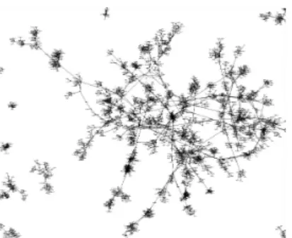
Dataset. We used a dataset of co-publications between INRIA researchers. We analyse this data set to produce visual results which have interesting insight for the INRIA scien- tific managers, and has to proceed while new publications are added to the database. This dataset includes about 4500 nodes and 35400 edges. The goal is to compute the attributes of each node and edge, display the graph over one or several screens and update it as the underlying data changes.
7.1 Layout procedure handlers
Our first goal was to validate the interest of procedure handlers in the context of data visualization. In our INRIA co-publication scenario, the procedure of interest is the one computing the positions of nodes in a network, commonly known aslayout. We use the Edge LinLog algorithm of Noack [14] which is among the very best for social networks, and provides aesthetically good results. What makes EdgeLinLog even more interesting in our context is that it allows for effective delta handlers (introduced as part of our process model in Section 5).
In our implementation, the initial computation assigns a random position to each node and runs the algorithm iteratively until it converges to a minimum energy and stabilizes.
This computation can take several minutes to converge but, since the positions are com- puted continuously, we can store the positions in the database at any rate until the algo- rithm stops. Saving the positions every second or at every iteration if it takes more than
0 5000 10000 15000 20000 25000 30000 35000
0 20000 40000 60000 80000 100000
Time (in ms)
# inserted tuples Inserting tuples in VisualAttributes table Inserting new nodes into the display Message parsing (change in Author table) Message parsing (change in VisualAttributes table) Extracting new nodes from VisualAttributes(select) Total time
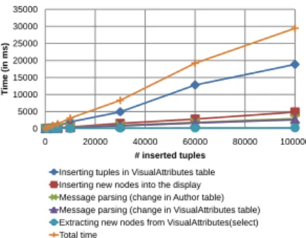
Figure 5: Time to perform insert operations.
Figure 6: Part of the graph of IN- RIA co-publications.
one second allows the system to appear reactive instead of waiting for minutes before showing anything.
If the network database changes, for example when new publications are added to/removed from the database, the handler proceeds in a slightly different manner. First, it updates the in-memory co-publication graph, discards the nodes that have been removed and adds new nodes. To each new node it assigns a position that is close to their neighbours that have already been laid-out. This is to improve the time and quality of the final layout.
If disconnected nodes are added, they are assigned a random position. Then, the algo- rithm is run iteratively like for the initial computation, but it terminates much faster since most of the nodes will only move slightly: the convergence of the iterations will be much faster. Like before, we store in the DBMS the results of some of the iterations to allow the visualization views to show them.
Using this strategy, we have obtained an incremental layout computation, remarkably stable and fast.
7.2 Robustness evaluation
Our second experimental goal was to study how the EdiFlow event processing chain scales when confronted with changes in the data. For this experiment, the DBMS is connected via a 100 MHz Ethernet connection to two EdiFlow instances running on two machines.
The first EdiFlow machine computes visual attributes (runs the layout procedure), while the second extracts nodes from VisualAttributes table and displays the graph. This second EdiFlow machine is a laptop.
We study the robustness of our architecture when adding increasing numbers of tuples to the database. Inserting tuples requires performing the sequence of steps below, out of which steps 1, 2 are performed on the first EdiFlow machine, while steps 3, 4 and 5 are performed on all machines displaying the graph.
1. Parsing the message involved after insertion in nodes table. It refers to step 7 in the protocol described in section 6.3.
2. Inserting the resulting tuples in the VisualAttributes table managed by EdiFlow in the
DBMS.
3. Parsing the message involved after insertion in VisualAttributes table. After inserting tuples, in VisualAttributes, a message is sent to all machines displaying the graph. The message is parsed to extract the new tuple information. It refers to step 9 in the protocol described in section 6.3.
4. Extracting the visual attributes of the new nodes, from the VisualAttributes table, in order to know how to display them at the client.
5. Inserting new nodes into the display screen of the second machine.
The times we measured for these five steps are shown in Figure 5 for different numbers of inserted data tuples. The Figure demonstrates that the times are compatible with the requirements of interaction, and grow linearly with the size of the inserted data. The dominating time is required to write in the VisualAttributes table. This is the price to pay for having these attributes stored in a place from where one can share them or distribute them across several displays.
8 Conclusion
In this article, we have described the design and implementation of EdiFlow, the first workflow platform aimed at capturing changes in data sources and launching a repair mechanism. EdiFlow unifies the data model used by all of its components: application data, process structure, process instance information and visualization data. It relies on a standard DBMS to realize that model in a sound and predictive way. EdiFlow sup- ports standard data manipulations through procedures and introduces the management of changes in the data throughupdate propagation. Each workflow process can express its behaviour w.r.t data change in one of its input relations. Several options are offered to react to such a change in a flexible way.
EdiFlow reactivity to changes is necessary when a human is in the loop and needs to be informed of changes in the data in a timely fashion. Furthermore, when connected to an interactive application such as a monitoring visualization, the human can interactively perform a command that will change the database and trigger an update propagation in the workflow, thus realizing an interactively driven workflow.
We are currently using EdiFlow to drive our Wikipedia aggregation and analysis database as a testbed to provide real-time high-level monitoring information on Wikipedia, in the form of visualizations or textual data [8]. We are also designing a system for com- puting and maintaining a map of scientific collaborations and themes available on our institutions.
We still need to experiment with it to find out the limitations of EdiFlow in term of performances, typical and optimal reaction time and ability to scale with very large applications.
We strongly believe that formally specifying the services required for visual analytics in term of user requirements, data management and processing, and providing a robust implementation is the right path to develop the fields of visual analytics and scientific workflows together. For more details, examples, pictures and videos of the usage of
EdiFlow, see the EdiFlow website:http://scidam.gforge.inria.fr/.
References
[1] Protovis. http://vis.stanford.edu/protovis/.
[2] A. Ailamaki, Y. E. Ioannidis, and M. Livny. Scientific workflow management by database management. InSSDBM, 1998.
[3] I. Altintas, C. Berkley, E.Jaeger, M. Jones, B. Ludascher, and S. Mock. Kepler: An extensible system for design and execution of scientific workflows. InSSDBM, 2004.
[4] E.W. Anderson, S.P. Callahan, D.A. Koop, E. Santos, C.E. Scheidegger, H.T. Vo, J. Freire, and C.T. Silva. VisTrails: Using provenance to streamline data exploration. InDILS, 2007.
[5] Michael R. Berthold, Nicolas Cebron, Fabian Dill, Thomas R. Gabriel, Tobias K¨otter, Thorsten Meinl, Peter Ohl, Kilian Thiel, and Bernd Wiswedel. KNIME - the Konstanz information miner: version 2.0 and beyond. SIGKDD Explorations, 11(1), 2009.
[6] Marco Brambilla, Stefano Ceri, Piero Fraternali, and Ioana Manolescu. Process modeling in web applications.ACM Trans. Softw. Eng. Methodol., 2006.
[7] S-M. Chan, L. Xiao, J. Gerth, and P. Hanrahan. Maintaining interactivity while exploring massive time series. InVAST, 2008.
[8] F. Chevalier, S. Huot, and J-D. Fekete. Wikipediaviz: Conveying article quality for casual wikipedia readers. InPaciViz, 2010.
[9] J-D. Fekete. The InfoVis toolkit. InInfoVis, 2004.
[10] Eibe Frank, Mark A. Hall, Geoffrey Holmes, Richard Kirkby, and Bernhard Pfahringer.
Weka - a machine learning workbench for data mining. InThe Data Mining and Knowl- edge Discovery Handbook. 2005.
[11] S. G.Parker and C. R.Johnson. SCIRun: a scientific programming environment for compu- tational steering. InACM SC, 1995.
[12] Ashish Gupta, Inderpal Singh Mumick, and V. S. Subrahmanian. Maintaining views incre- mentally. InACM SIGMOD, 1993.
[13] Zachary G. Ives, Todd J. Green, Grigoris Karvounarakis, Nicholas E. Taylor, Val Tannen, Partha Pratim Talukdar, Marie Jacob, and Fernando Pereira. The ORCHESTRA collabora- tive data sharing system. SIGMOD Record, (3), 2008.
[14] Andreas Noack. An energy model for visual graph clustering. InProceedings of the 11th International Symposium on Graph Drawing, volume 2912 ofLNCS, 2004.
[15] A. Rygg, P. Roe, and O. Wong. GPFlow: An intuitive environment for web based scientific workflow. In Proceedings of the 5th International Conference on Grid and Cooperative Computing Workshops, 2006.
[16] S. Shankar, A. Kini, D.J. DeWitt, and J. Naughton. Integrating databases and workflow systems.SIGMOD Record, 2005.
[17] J. Thomas and K. Cook, editors. Illuminating the Path: Research and Development Agenda for Visual Analytics. IEEE Press, 2005.
[18] Project Trident: A scientific workflow workbench. http://research.microsoft.com/en- us/collaboration/tools/trident.aspx.