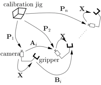
Algebraic analysis of the linear formulation determines whether the calibration is partial or complete according to the nature of the movements. It was also shown, both algebraically 30] and geometrically 4], that a sufficient condition for the uniqueness of the solution is the existence of two calibration motions with non-parallel rotation axes. The pose algorithms require the 3d Euclidean coordinates of the gyro targets along with their associated 2d projections in each image.
The second idea is that camera movements can be calculated from structure-out-of-motion algorithms rather than pose algorithms, to avoid using the calibration jig. In the linear formulation of the problem, we use the linear operator vec and the tensor product, also called the Kronecker product. To avoid this two-step solution, which propagates the error of the rotation estimate to the translation, a non-linear minimization method based on the representation of the rotations with unit quaternions was proposed.
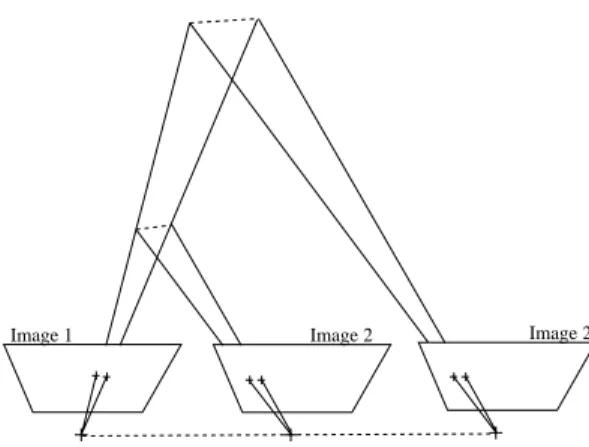
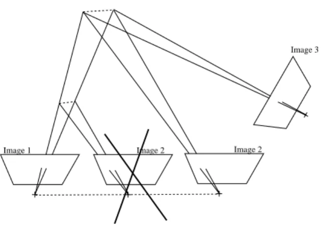
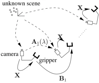
Then, from the 3d coordinates of the targets, their 2d projections and the intrinsic camera parameters, the pose (i.e. position and orientation) of the camera with respect to the calibration jig is estimated Pi= (Riti). From this knowledge, one can reconstruct the structure of the scene and the movement of the camera to an unknown scale factor (Fig. 4) using various methods (see. This unknown scale factor is the global scale factor of the observed scene and is the same for all the camera movements in the sequence (Fig. 5).
Consequently, the uai's are related to: uai = tai=kua1k and can be interpreted as the unknown norm of the first translation.
Using structure-from-motion
Linear formulation
Algebraic analysis
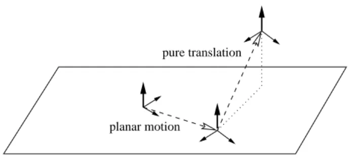
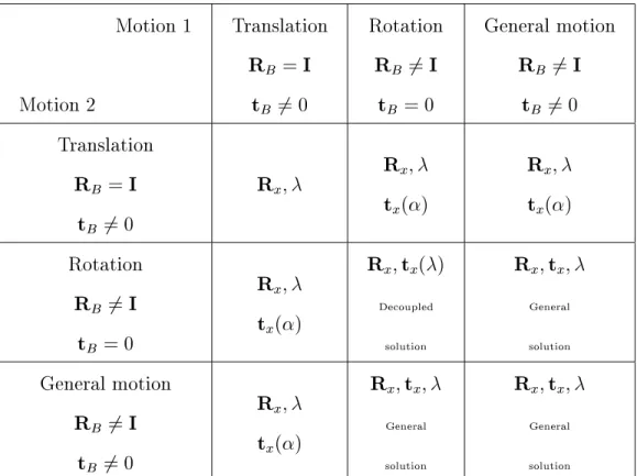
- Pure translations
- Pure rotations
- Planar motions
- The general case
Theorem 1 Three independent unbiased translations yield a linear estimate of hand-eye rotation Rx and of the unknown scale factor. However, the nine coefficients of the hand-eye rotation Rx can be obtained as we show below. Theorem 2 A minimum of 2 linearly independent unbiased translations are intrinsically enough to estimate the hand-eye rotation Rx and the unknown scale factor.
Proposition 3 If the end-effector of the robot undergoes at least two pure rotations with non-parallel axes, then the hand-eye rotation can be linearly estimated. Note that, in the case where the camera motion is captured through pose computation, the hand-eye translation is known and can be fully recovered, as Li 19] does. This is not surprising since the pure rotations of the robot do not contain metric information.
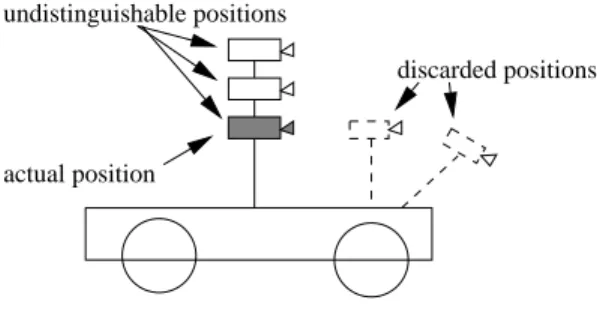
The hand-eye translation can only be estimated up to an unknown height along the normal to the camera's plane of motion (Fig. 8). In the latter two cases, the hand-eye translation can only be estimated up to an unknown height along the normal to the camera's plane of motion (Fig. 8). In conclusion, we showed sufficient conditions to obtain, from two plane movements, the hand-eye rotation and the hand-eye translation, to a component perpendicular to the camera's plane of motion.
In the case of a car, this unknown component can be interpreted as a height relative to the foot of the car (Fig. 8). In the case of two independent general motions with non-parallel axes, a unique solution to the hand-eye calibration problem exists. Proposition 5 If the end-eector of the robot undergoes two independent general motions with non-parallel axes, then the hand-eye transformation (Rxtx) can be fully recovered, as well as the Euclidean reconstruction unknown scale factor.
Therefore, the solution to self-calibration of the eye by hand is a vector 131 contained in a 1-dimensional subspace. It can therefore be extracted from this zero space by applying the unity constraint to the first 9 coefficients representing the hand-eye rotation, as seen in the case of pure translation. However, Wei et al 32] observed, in the case where camera movements are obtained through pose computation, that the accuracy of simultaneous estimation of hand-eye rotation and translation is not independent of the physical unit used for the translation.
On the opposite side, a two-step solution, as in 30], guarantees an orthogonal estimate of the hand-eye rotation. So we have a unique linear solution for the hand-eye translation and the scale factor.
Error measurement
In this section, we will first choose a distance to measure the errors between rigid transformations, since their group SE(3) does not have an intrinsic metric 20]. Second, we will show some simulation results to test the robustness of our method to noise compared to the reference methods. In this section, we numbered the methods we compared as follows: axis/angle method 30] (M1), double quaternion method 8] (M2), nonlinear minimization 15] (M3), our linear formulation adapted to cases where camera movements are achieved through pose calculation (M4) and self-calibration (M5).
Simulations
- Simulation procedure
- Inserting noise
- Robustness to noise
- In uence of motion number
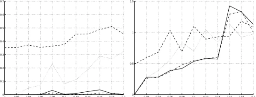
As for the camera rotations, we added noise to their Roll-Pitch-Yaw angles as ~= (1 +r), where any of these angles is the same as translation and r is 1-dimensional white noise. We tested the value, making it vary from 0 to 20% in two simulation runs. In the first, we made 100 different choices of hand-eye transformations and movement sequences for each noise level.
These sequences contained only two movements, with a maximum amplitude of 1 m in translation and 180 degrees in rotation. It shows that the method of Tsai and Lenz (M1) and ours (M4) achieve the highest accuracy in rotation. They are very robust for translations as long as the noise level is low, but are less accurate than the double quaternion method (M2) or the nonlinear minimization method (M3) when the noise level increases.
In the second series of simulations, we almost repeated the first, only reducing the amplitude of the calibration movements to 2 cm in translation and 10 degrees in rotation. The results (Figure 10) show that our linear formulation is less sensitive to this reduction than other methods. In this experiment, we kept the noise level constant (= 0:01) and created sequences of different lengths, i.e.
For each sequence length, we proceeded to 100 random selections of hand-eye transformations and calibration movements.
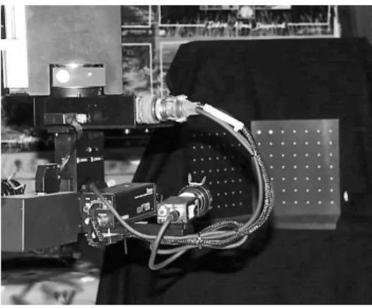
Experiments on real data
Experiment 1
We therefore took images of our calibration grid (Fig. 12) and performed hand-eye calibration using the axis/angle method 30] (M1), the dual quaternion method 8] (M2), the nonlinear minimization 15 ] (M3) and the linear formulation (M4). Finally, using the same points, extracted from the images of the calibration grid, but not their 3D model, we applied the hand-eye self-calibration method (M5). These positions were chosen as far apart as possible according to the advice given in 30].
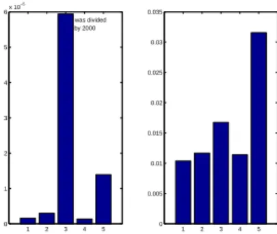
It can be seen that (M4) gives the smallest rotation error due to the numerical efficiency of SVD and thus also obtains a reduced translation error. However, the degradation is quite small and can be explained by a rough estimate of the intrinsic parameters. It confirms that the linear method is numerically very efficient, especially as far as rotation is concerned.
Moreover, the self-calibration method gives a lower accuracy, which nevertheless remains acceptable in the context of visual servicing 11].
Experiment 2
They also show slightly higher performance degradation (M5) compared to the others. To balance the lack of ground truth, we also compared the results obtained in this experiment with the robust estimation described in Experiment 1 (Table 3). This comparison confirms the accuracy of both the linear method and the self-calibration scheme.
We proposed a hand-eye self-calibration method, which reduces the human supervision compared to classical calibration methods. The cost of releasing the human constraint is a slight degradation of numerical accuracy. This method is based on the structure-from-motion paradigm, rather than pose estimation, to calculate the camera movements, and its derivation includes a new linear formulation of hand-eye calibration.
We therefore determined the parts of the hand-eye transformation that can be obtained from a reduced number of movements that do not allow a complete calibration. Moreover, the linear formulation provides improved numerical accuracy even in the case where the camera/robot rotations have small amplitude. However, this requires tracking the points from the start to the end of the robot path.
This is a hard limitation since in practice one hardly gets enough points after a long trajectory. Stereo vision can provide the answer to this problem, since it has been shown that Euclidean reconstruction can be performed, without any prior knowledge, from two Euclidean movements of a stereo pair 10]. Finally, there is a pending question that was never answered: \What are the motions for hand-eye (self-)calibration that yield the higher numerical accuracy?".
Preliminary results
If R satisfies the first equation, then R is either the identity or has the same rotation axis as R1.
Proof of Lemma 1
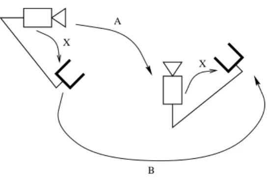
Consequently, the matrix V extracted from the null space in (26) is proportional to the hand-eye rotation. Calibration of wrist-mounted robotic sensors by solving homogeneous transformation equations of the form AX=XB.