The CCSDS 121.0-B-2 Lossless Data Compression standard defines a lossless adaptive source coding algorithm applicable to a wide range of imaging and non-imaging data. This thesis presents two FPGA implementations of CCSDS 121.0-B-2, one 32 bit focused on data streams and one 16 bit focused on space images. Vitulli, “A Reconfigurable FPGA Implementation of CCSDS 121.0-B-2 Lossless Data Compression”, 4th International Workshop on On-board Payload Data Compression – OBPDC’2014, co-organized by ESA and CNES, Venice, October 2014.
Vitulli, “An Efficient FPGA Implementation of CCSDS 121.0-B-2 Lossless Data Compression Algorithm for Image Compression,” Journal of Applied Remote Sensing (JARS), Volume 9, Issue, Special Issue on Embedded Compression and Processing for Space Data Systems, May 2015 This master's thesis presents two IP core implementations of the CCSDS 121.0-B-2 Lossless Data Compression standard, one 32 bit focused on data streams and one 16 bit focused on space images.
INTRODUCTION
Background
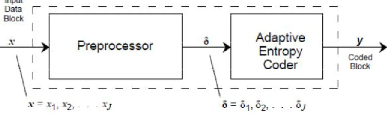
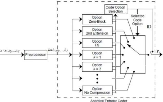
A lossless compressor as recommended in CCSDS-121.0-B-2 consists of two separate parts: a) a preprocessor and b) an adaptive entropy encoder (AEC), as shown in Figure 2-1. The recommended standard in CCSDS-121.0-B-2 focuses on standardizing the rightmost block in Figure 2-1, the Adaptive Entropy Coder, since the preprocessor is application dependent. The AEC unit supports all 33 coding options defined in the CCSDS-121.0-B-2 standard: the basic sequence (FS) option, the 29 k-th split pattern options, two low-entropy options (second expansion and null block), and the "no compression". The AEC unit has the following features: a) selectable block size (J or 64, b) supports basic or limited set of code options, and c) reference sample interval (r) from 1 to 4096. Coding option selection unit calculates in parallel the total compression cost of each available coding option (taking into account the code ID bits) and selects the coding option that gives the highest compression ratio among the different options on the same block of J samples. The selected option for the block is selected as follows: a) the.
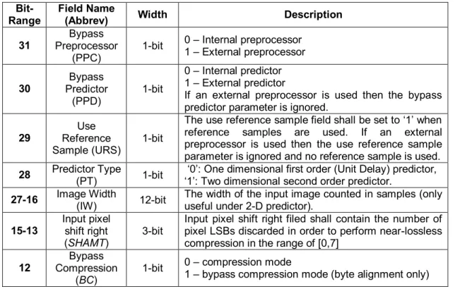
Both versions of the CCSDS-121 IP Core are controlled by the control register shown in Table 2-6. The operating modes of both versions of the CCSDS-121 IP core are shown in Figure 2-6 along with the control software commands. The width of the input/output parallel interfaces for the CCSDS-121-I/D IP core is 16/32-bit.
The list of test stimuli for the two versions of the CCSDS-121 IP core is shown in Tables Table 2-10 and Table 2-11. The device usage summaries for the Image and Data versions of CCSDS-121 IP Core after synthesis are reported in Table 3 Error. The timing reports for the image and data versions of CCSDS-121 IP Core after Place.
Lists of test stimuli for the image and data versions of the CCSDS-121 IP Core are shown in Table 3-11 and Table 3-12.
CCSDS 121.0-B-2 Lossless Data Compression
CCSDS 121.0-B-2 LOSSLESS DATA COMPRESSOR ARCHITECTURAL
Algorithm Operation
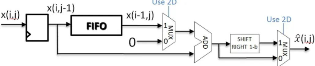
The price you pay is generally a lower compression ratio, which is defined as the ratio of the number of original uncompressed bits to the number of compressed bits, including the overhead required for signaling parameters. The preprocessor function is a reversible operation and, in general, the best lossless preprocessor will satisfy the above conditions and produce the lowest entropy, which is a measure of the smallest average number of bits that can are used to represent each sample. One of the simplest predictors is a first-order linear unity-delay predictor, where the output, Δi, is the difference between the input data symbol and the previous data symbol.
In Rice's coding technique, several algorithms are applied simultaneously to a block of J consecutive preprocessed samples. To provide compressed data rates of less than 1.5 bit/sample, the CCSDS-121.0-B-2 includes two low-entropy options that are particularly efficient when the preprocessed samples consist of only small values. When the Second-Extension option is selected, the encoder first pairs consecutive preprocessed samples from the J sample block and then transforms the paired samples into a new value, gamma, which is encoded.
The Zero-Block option is a special case when one or more blocks of preprocessed samples are all zero. In this case, a single codeword represents one or more consecutive all-zero blocks of J preprocessed samples. Since the block size J can be small and a new code option is chosen for each block, the overall coding can adapt to rapid changes in data statistics.
The general purpose Adaptive Entropy Coding of CCSDS-121.0-B-2 is shown in the figure below along with a preprocessor.

CCSDS-121.0-B-2 Lossless Data Compressor Architecture
- Top Level Architecture
- Preliminary Stage
- Preprocessor
- Adaptive Entropy Coding
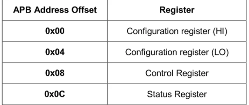
Configuration and control of both versions of the CCSDS-121 IP core is implemented by AMBA APB memory card system registers) and therefore can be accessed by standard serial link interfaces such as SpaceWire-RMAP or SPI. Both versions of the CCSDS-121 IP core are highly integrated, single FPGA implementations without requiring any external memory for data buffering (no additional memory chip acquisition, lower cost, bulk and power costs, and no memory interface implementation bottlenecks). An asynchronous reset input signal drives the two CCSDS-121 IP Cores to the initialization (INIT) state.
CCSDS-121.0-B-2 IP cores, c-ldc, were used to verify the software gold reference model of the CCSDS-121.0-B-2 standard developed by the DSCAL team. The Szip tool also implements the previous version of the lossless data compression standard, CCSDS 121.0-B-1. These test environments use test stimuli and validate the CCSDS-121 IP Core by measuring test responses and comparing them to expected/golden test responses.
The post-synthesis timing summaries for the Image and Data versions of CCSDS-121 IP Core post-synthesis are reported in Table 3-3 and Table 3-4. The device usage summaries for the Image and Data versions of CCSDS-121 IP Core to Location & Route are reported in Table 3-5 and Table 3-Table 3-6. The measured total (static and dynamic) power consumption for the Image and Data versions of CCSDS-121 IP Core, their operating frequencies are reported in Table 3-9 and Table 3-10.
Data rate (usage) performance for image and data versions of the CCSDS-121 IP Core for different images and compression modes are shown in Table 3-13 and Table 3-1.
CCSDS-121.0-B-2 Lossless Data Compressor Configuration
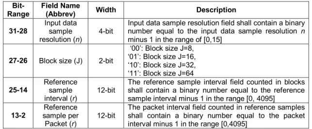
- Configuration Register
- Control Register
- Status Register
CCSDS-121.0-B-2 Lossless Data Compressor Modes of Operation
CCSDS-121.0-B-2 Lossless Data Compressor System Interfaces
- System Interfaces
- Timing Diagram
The two CCSDS-121 IP cores provide two First-Word-Fault (FWFT) FIFO-based parallel interfaces for stream data input (upstream i.e. uncompressed sensor data) and stream data output (downstream i.e. encoded bitstream output). In case the data sample resolution (n) is smaller than the input width, the CCSDS-121 IP core performs zero or sign extension internally for the 16/32-n MSBits, depending on given configuration. An End-of-Stream (datain_EOS) flag on the data input indicates the end of the input stream.
The IP core asserts the dataout_EOP flag concurrently with the last compressed byte of the packet. The End-Of-Stream flag (dataout_EOS) on the data output signals the end of the output stream. The IP core asserts the dataout_EOS and dataout_EOP flags concurrently with the last compressed byte of the stream.
The two CCSDS-121 IP Cores offer an AMBA APB Slave interface to enable access to memory-mapped registers (configuration, control and status), therefore they can be accessed through standard serial link interfaces such as SpaceWire-RMAP or SPI. The two CCSDS-121 IP Cores are capable of operating with a clock that differs from the one used by the AMBA bus to which it is connected. The CCSDS-121-I IP core block symbol is illustrated in Figure 2-7, the CCSDS-121-D IP core block symbol is illustrated in Figure 2-8, while the detailed list of interface signals for both versions is shown in Table 2-9.
The following timing diagram shows the initialization/configuration of the CCSDS-121 IP core using the AMBA APB interface and its normal operation using the simple FIFO-based parallel data stream interface.

CCSDS 121.0-B-2 Lossless Data Compressor Verification
- Software golden reference model
- Testbench environment, stimuli and expected test responses
- Code coverage measurements
Each testbench environment consists of a simulation master script (in TCL format, compatible with Mentor's Questa Simulator), a test database file, a VHDL test panel with the IP core, and six output files. The TCL simulation script starts the execution of a simulation suite and is responsible for parsing the input arguments, compiling the source code, and running all the simulations described in the test file. Optionally, it can verify each test's responses and/or generate code coverage statistics for each test and the suite as a whole.
For each test in the simulation batch, there is a line in this file that gives a pass/fail depending on the golden answer. For the tests that failed the verification process, there is one line in this file that is an identical copy of the test's entry in the test file, making it easier to debug by running the tests that failed the verification. For each test in the simulation batch, there is one line in this file that shows the number of clock cycles required to complete the simulation to calculate the throughput performance.
The code coverage reports for the test in the simulation batch generated by the simulation tool in ".html" and ".ucdb" formats. CCSDS test data: datasets with 432, 1024, and 2048 inputs and dynamic range 8, respectively, exercising the second extension and zero-block coding options designed for low-entropy input data. The industry standard HDL simulation tool Questa Advanced Simulator from Mentor Graphics was used for simulation at the preliminary design level (VHDL RTL verification).
The code coverage reported by Questa Advanced Simulator is 100% for all statements in the hierarchy levels, except for FSM descriptions that include the VHDL other statement.

CCSDS 121.0-B-2 LOSSLESS DATA COMPRESSOR IMPLEMENTATION
Netlist Generation and Verification
- Netlist Generation
Post Place & Route Generation and Verification
- Post Place & Route generation
- Post Place & Route Verification
For layout verification by time simulation, the VHDL test benches were developed at the preliminary design stage targeting the VHDL RTL source used targeting the Post Place & Route Netlist. These test benches, most in the form of PASS/FAIL tests, use test stimuli and verify the CCSDS-121 IP Core by measuring test responses and comparing to expected/golden test responses. Test stimuli comprise a limited subset of the selection of test images used in preliminary design simulation-based verification.
Similar to the preliminary design phase, the expected/golden assay responses were captured using the developed c-ldc gold standard reference model.

Data-rate performance
CONCLUSIONS
ABBREVIATIONS - ACRONYMS Application Specific Integrated Circuit AMBA Advanced Microcontroller Bus Architecture APB Advanced Peripheral Bus. VHDL VHSIC Hardware Description Language VHSIC Very Fast Integrated Circuit XST Xilinx Synthesis Tool.