I would like to express my deep appreciation to Beáta Kiss for her patience and unconditional support over all these years. Ac BRB cross-section of the steel core in the yielding zone K1 first branch stiffness (i.e. initial stiffness).
INTRODUCTION
BACKGROUND AND MOTIVATION
- General characteristics of dissipative structural solutions
- Buckling Restrained Braced Frames
- Concept of BRBF design
- Standardized design procedure development and evaluation for BRBF
The required load capacity of the elastic elements is based on the maximum possible axial force in the connecting clamps at the level of designed deformation. Changes in the design process are directly applied to a set of structures and are reflected in their performance.
METHODOLOGY
- Evaluation procedure
- Primary tasks
- Scope
Results from experimental analyzes and the available information from the literature are used to develop a bilinear relationship similar to the US backbone curve that can be applied for BRBF design. The analysis proposed in FEMA P695 forms the basis of the design procedure evaluation in the fourth phase of this study.
ORGANIZATION
The design of the BRB element (normally completed by the manufacturer) ensures that BRBs have sufficient resistance to local failure in their connections and local flexural buckling of their steel core outside its yield zone.
EXPERIMENTAL ANALYSES OF BUCKLING RESTRAINED BRACES
- STATE OF THE ART
- Initial type tests
- Advanced testing and popular topics
- Large scale experiments and innovative elements
- TEST OBJECTIVES
- Specimen characteristics
- Design considerations and complementary objectives
- DESIGN OF EXPERIMENTS
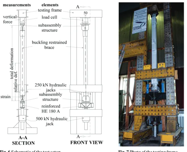
- Experimental setup
- Design displacement
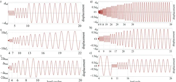
- Load protocols
- EVALUATION OF BRB BEHAVIOR
- Failure and disassembly
- General BRB performance
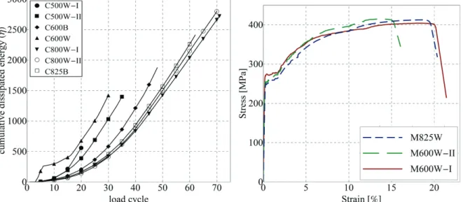
- Energy dissipation capacity
- Monotonic tensile response
- EVALUATION OF BRB DESIGN PARAMETERS
- Eurocode-conform design of BRBs
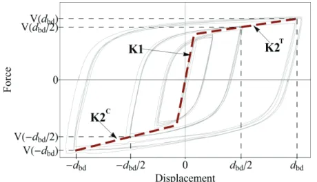
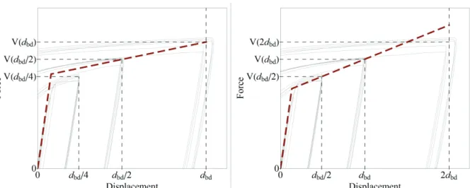
- Representation of BRB behavior in EN 15129 and its disadvantages
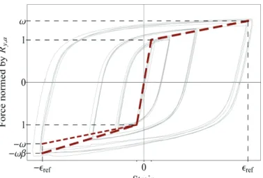
- Alternative approach to description of the BRB backbone curve
The flexural deflection of the BRB element (also called the global element deflection) is primarily controlled by the case configuration. Stiffness values are based on experimental data in the background image.
NUMERICAL UNIAXIAL BRB MODEL DEVELOPMENT
STATE OF THE ART
- Element-level analysis
- Global analysis of braced frames
- Modeling issues in global nonlinear dynamic analysis
- Problem statement and objectives
The complexity of the performed analysis determines the required modeling accuracy and the type of material model we need. Response history analyzes can only provide realistic results if the behavior of structural elements and ground motion hazard characteristics are modeled with sufficient accuracy.
![Fig. 21 A detailed numerical BRB model example (figure courtesy of Viktor Budaházy [Z3])](https://thumb-eu.123doks.com/thumbv2/9dokorg/2496719.294088/34.892.189.816.85.460/detailed-numerical-model-example-figure-courtesy-viktor-budaházy.webp)
MODELING BRB BEHAVIOR BY COMBINATION OF THREE CONVENTIONAL MATERIAL
- Modeling concept
- Components
- Model configuration and performance
- Shortcomings and possible issues
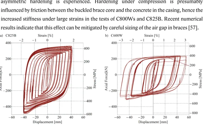
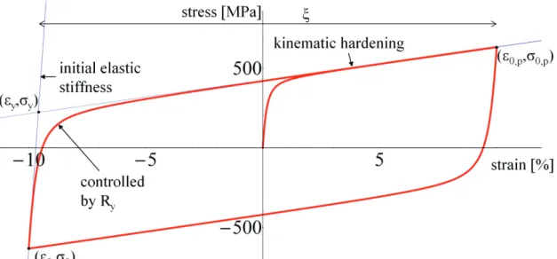
Therefore, asymmetric hardening can be imagined as an increase in the effect of kinematic and isotropic hardening. The disadvantage of the nonlinear spring is that its behavior is strain-dependent, so the isotropic part of the asymmetry cannot be taken into account.
DEVELOPMENT OF A GENERAL PURPOSE UNIAXIAL STEEL MATERIAL
- The Menegotto-Pinto steel material model
- Improvements over the nonlinear kinematic hardening formulation
- Extension with isotropic hardening
- Yielding point evaluation
- Model verification
44 Comparison of the stress-strain response and the displacement history of an SDOF system together with. 46 Comparison of the stress-strain response and the displacement history of an SDOF system together with a.
MODELING BRB BEHAVIOR WITH THE STEEL04 MATERIAL
- Consideration of low cycle fatigue for BRBs
- Evaluation of general BRB material model parameters
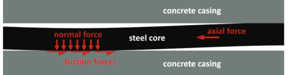
The increased stiffness of the element is presumably caused by the interaction between the concrete shell and the steel core through friction. Yield area reduction is not expected under increasing cumulative plastic deformations, so there is no strong theoretical background for the implementation of such a feature in the material model. These elements are more sensitive to the size of the gap around the core.
Experimental results show that some specimens did not have enough space for the steel core to expand under compression, and the core was stuck in the concrete casing at large deformations.
STATE OF THE ART
- Probabilistic seismic performance assessment
- Fragility curve evaluation as per FEMA P695
- Result uncertainty and spectral shape approximation
- Design procedure assessment
- Alternative BRBF design procedures
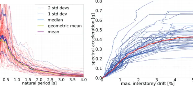
Collapse intensity (i.e. the spectral intensity at the dominant period of the structure initiating global failure) is considered as a random variable with lognormal distribution and it is described by a fragility curve (eg Fig. 55). A spectrum with a positive ε(T) has a peak in the vicinity of the T period as shown in Fig. The basis of safety in the Eurocodes is reliability, namely the probability of failure over the lifetime of the structure.
Several studies are only interested in the evaluation of the optimal behavior factor (q) to be used for this system [17,86].
BRBF DESIGN PROCEDURE FOR EUROPEAN APPLICATION
- Proposed modifications in the capacity design procedure of Eurocode 8
It is proposed that the standard prescribe the need to check struts against stability failure and allow the manufacturer to take responsibility and carry out these checks in accordance with EN 15129. Unbalanced loads due to asymmetric bracing should be considered for strut frame columns that have at least two connecting clamps. A stricter variation limit for strut stiffness (Ω) with respect to the height of the structure is proposed.
The value of adjustment factors corresponding to the design deformation level (εd) must be calculated using the design envelope response of stiffeners described in terms of the backbone curve with the SAM method shown in section 2.5.3.
SAMPLE PERFORMANCE EVALUATION
- Structural design
- Numerical BRBF model
- Nonlinear static analysis
- Nonlinear Dynamic Analyses
- Fragility curve evaluation
- Reliability analysis
This agrees well with the 1.529 s of the design model of the previous subsection. The SSF is a function of μT and T1 (i.e. the first mode period of the structure) and it also depends on the seismic properties of the site under consideration. It calculates the expected failure probability of the structure over its design life of 50 years.
65 shows the hazard curve probability density function (PDF) based on the assumption of lognormal data distribution as well as the cumulative distribution function (CDF) of the conditional probability of failure for the structure.
SENSITIVITY ANALYSIS
- Numerical model
- Design procedure
- Result evaluation
This concludes the analysis of the sample structural representation of the proposed BRBF design procedure. Note also that the 0.5% strain limit leads to failure of the first model due to column failure. The influence of the selected values for ω and β for the calculation of structural superhardness is shown by the following example.
77 Effect of the number of intensity steps chosen in IDA on the accuracy of collapse probability.
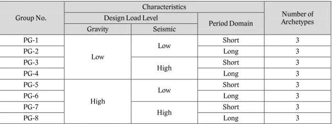
INVESTIGATED SCENARIOS
- Performance Groups
- Structural archetypes
- Automated BRBF design
That research is beyond the scope of this dissertation, so the analyzes presented in the following use only one typical site for each PGA level. Regions of moderate and very high seismicity are considered as the two seismic hazard cases to verify the applicability of the proposed procedure at both ends of the seismic intensity spectrum. The short-period domain set contains stiffer structures with dominant periods typically below Tc of the corresponding design spectrum.
The design of braced frames is performed automatically by an algorithm developed by Tamás Balogh.
RESULT EVALUATION
- Discussion of results for all archetypes
- Design procedure assessment
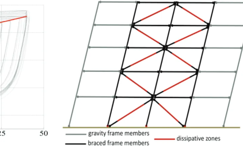
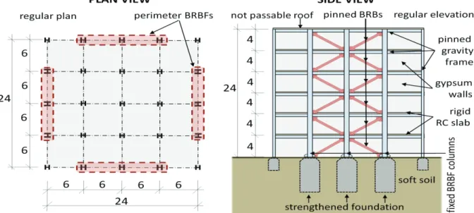
The beneficial behavior experienced in buckling of restrained braced frames during numerical analyzes stems not only from the high ductility and energy dissipation of the braces, but also from the application of an appropriate design procedure. The number of floors varies from 2 to 6, and the height of the structure varies from 8 to 24 meters. The braced floor area corresponding to each braced frame in the structure is within the range 2b2 and 5b2, where b is the distance between the outer columns of the braced frame.
Investigation of additional archetypes in the future will lead to a better understanding of BRBF behavior and allow relaxation of the above constraints.
SUMMARY AND CONCLUSIONS
PRIMARY RESULTS OF THE PRESENTED RESEARCH
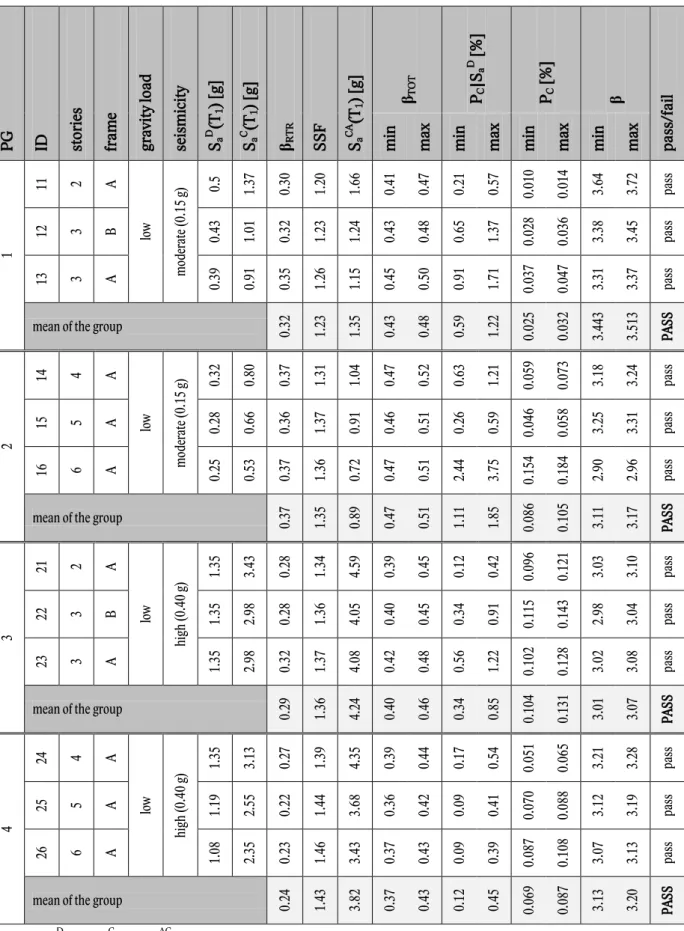
The applicability of the developed design procedure was verified by designing and evaluating the failure probability of 24 BRBF archetypes covering most of the parameter space for typical pinned BRBF applications. Reliability indices were evaluated for BRBF archetypes, providing information on the expected range of acceptable values for structural reliability in a seismic environment.
APPLICATIONS AND FUTURE WORK
Ongoing research on the performance of concentrically braced frames will provide initial guidance for this proposal, but further studies of other dissipative frame solutions are needed before any conclusions can be drawn.
NEW SCIENTIFIC RESULTS
Z5] Zsarnóczay Á., Vigh L.G.: Element level modeling of the cyclic behavior of buckling restrained braces (in Hungarian), XI. Z8] Zsarnóczay Á.: Impact of plastic mechanism development on the seismic performance of flexural restrained braced frames – case study, Proc. 18] Bosco, M., Marino, E.M.: Design method and behavior factor for flexurally restrained steel frames, Earthquake Engineering and Structural Dynamics.
73] Prinz, G.S., Richards, P.W.: Seismic Performance of Buckling Restrained Span Frames with Eccentric Configurations, Journal of Structural Engineering.
DETAILED EXPERIMENTAL DATA FOR EACH SPECIMEN
CHARACTERISTICS OF TESTED BUCKLING RESTRAINED BRACES
METHODOLOGIES FOR QUALITY CONTROL
Specifications in EN 15129
Alternative methodology
It does not prevent researchers from using different load protocols for testing if the tests include the EN 15129 load protocol with at least 10 load cycles at an amplitude greater than or equal to εref. An additional advantage of the alternative proposal is the direct connection with the calculation of structural overstrength. Uncertainty in hardening can be accounted for by simply multiplying the overhardness values for the non-dissipative terms by a factor of (1+κωβ) (assuming that the increase in hardening from ωβ is the change in compressive overhardness is the main effect).
The proposed alternative methodology for quality control of BRBs is currently being applied in practice by SSE.
BRB ELEMENT MODELING
Modeling with a series of beam elements
Note that the cross-sectional area of the steel core is not constant in the transition zone (Fig. 2). Using the average of the two connected zones in the form of Atr = (Ael + Ay)/2 can provide sufficient accuracy for global analysis. Because these calculations are typically performed by an automatic algorithm, it is recommended to improve accuracy by calculating the exact value of Atr.
Single element approach
Solving the equation for Eeq,0 and applying the expression from Eq. 52) for the equivalent surface of the transition zone gives: The significant decrease in BRB stiffness after yielding is due to the inelastic behavior of the yield zone. Note that the denominator of the fraction in Eq. Therefore, the relationship can be simplified to the following form for practical purposes:
20 The exact value of this factor is always calculated by the BRB manufacturer based on the geometry of the designed braces.

MODELING EXAMPLES FOR THE COMBINED MATERIAL
Example model in ANSYS
Provided that the behavior of the BRB steel core material has been modeled correctly, the model can be recalibrated to describe the nonlinear behavior of an element based on its geometry using the above equations for elastic and plastic behaviour.
Example model in OpenSees
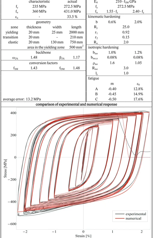
DETAILED DATA ON STEEL04 CALIBRATION TO BRB TESTS
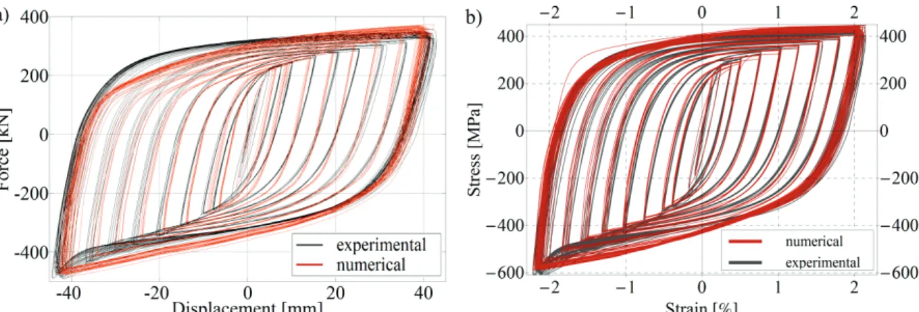
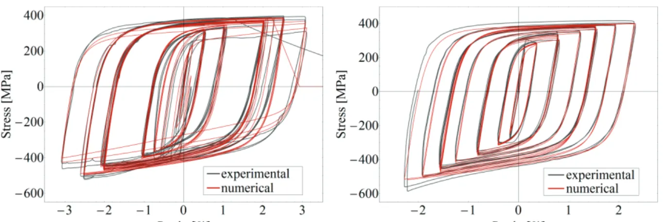
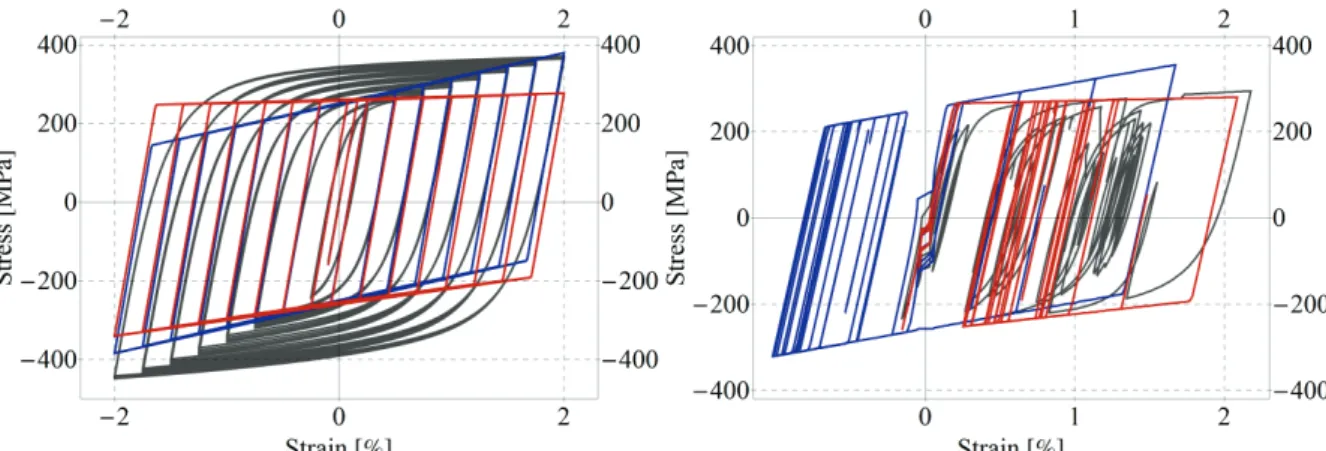
The parameters in table B3.16 for the proposed BRB element have been selected using the logic explained in section 3.4.2. Note that Table B3.16 contains the same information as Table 3 and is repeated here for the convenience of the reader only. The following figures compare the numerical response of the general BRB model with the experimental data for each instance of BME and UCSD, similar to the previous section.
DETAILED RESULTS FOR BRBF ARCHETYPES
NEW SCIENTIFIC RESULTS IN HUNGARIAN
II/b Kidolgoztam az acélanyag új fenomenológiai modelljét, amely továbbfejleszti a Menegotto-Pinto modellt és adaptáltam az OpenSees végeselemes környezethez (mint Steel04 modell). A Steel04 modellt a BME és UCSD kísérleti eredményekre kalibrálva létrehoztam a vizsgált BRB elemek általános modelljét. A FEMA P695 módszertanon alapuló eljárással igazoltam, hogy az Eurocode 8 teljesítménytervezési szabályai disszipatív, központilag megerősített acélvázakra alkalmasak csuklós, kettős keretű, hajlítórudakkal erősített, megfelelő kiegészítésekkel ellátott chevron rácsostartók tervezésére.
III/a A FEMA P695-ben szereplő módszertan alapján kifejlesztettem egy egyedi alkalmazást, amely képes bármely épületarchetípus meghibásodásának valószínűségét megbecsülni.