Three theses are presented and proven to solve the current problem in the integration of vertical and longitudinal vehicle dynamics and semi-active suspension control. Furthermore, optimal driving comfort and roadholding performance must be ensured by considering the allowable operating clearance of the vehicle's suspension (Gillespie [1992]).
![Figure 1.1: Scheme of a wheel-to-chassis suspension (Savaresi et al. [2010a]).](https://thumb-eu.123doks.com/thumbv2/9dokorg/2498191.294451/11.892.227.662.627.948/figure-scheme-wheel-chassis-suspension-savaresi-et-al.webp)
Problem Statement and Contribution
In this control approach, the control input can satisfy the saturation constraint; with this, the dissipative constraint can be satisfied.
Overview of the Thesis
The summary of the thesis is highlighted and future research directions are defined in Chapter 6. Finally, robust control design methods, which are H∞ robust control based on linear models and LP V system analysis and design, are presented in Appendix A. and a description of the TruckSim simulation environment is presented in Appendix B.
Literature Review
- Semi-active Suspension Control
- Adaptive Semi-active Suspension Control
- Fault-tolerant Control
- Conclusion of Literature Review
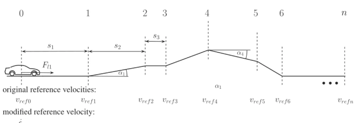
- Velocity Design based on the Road Information
In the following study (Sohn et al.[2004]) with the LQG control method, the semi-active adaptive suspension controller of road variations is proposed. Next, the road-adaptive semi-active suspension controller is designed with the LPV control method.
Semi-active Suspension Control for Passenger Comfort and Road Holding 18
LPV Control Synthesis
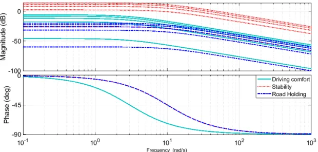
The frequency response of the band distortion should be small at [0-20] Hz to reduce variations of side force to guarantee stability. An A-chassis acceleration sensor can be used to measure the vertical acceleration of the vehicle.
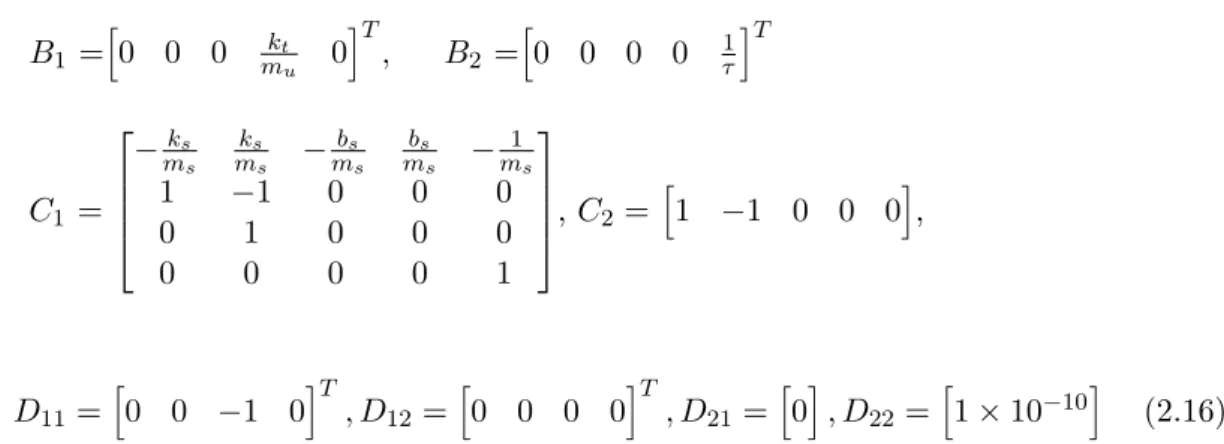
Actuator Model
Due to the controlled damper constraints, the following clipping function D(Fdin,(q1−q2)) is defined (Savaresi et al. [2010b]):. 2.17) where Fdin is the required power given by the controller and Fd⊥ is in the orthogonal projection of the Fdin in D. This scheduling variable selection procedure for different road irregularities and vehicle speed is the critical point for the road adaptability of the designed control system.
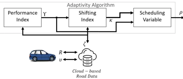
Road Adaptivity Methods
The choice of driving variable depends on the results of operation with the passive suspension system. This method is based on the comparison of performance results in the relevant speed and road category in the database.

Modeling of the Components
Velocity Controller Design
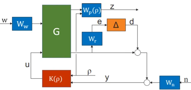
The maximum forces of drive lines and braking systems are determined by their physical construction limits. The proposed speed tracking controller is based on a weighting strategy formulated through a closed-loop architecture shown in Figure 2.16.
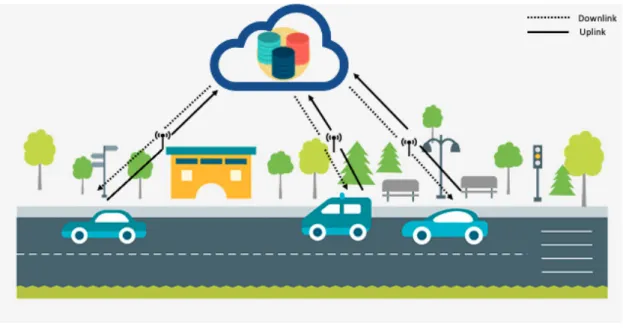
Database Design
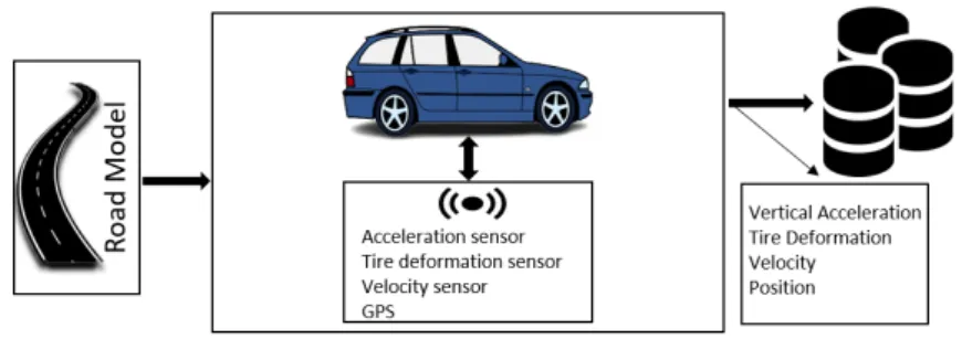
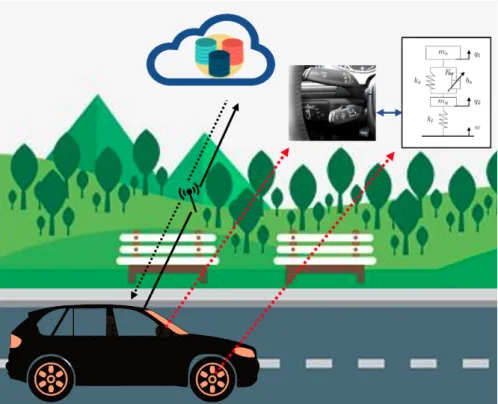
Various measurements of the vehicle equipped with passive suspension were collected and stored in the designed database. The data is collected by the on-board unit of the vehicle with multiple sensors (GPS, acceleration, tire deformation, speed). The cloud system provides access to the database as needed for cloud computing and the design of the scheduling variable.
Performance Analysis and Evaluation Methods
Analysis Methods
This method is considered to calculate and evaluate the vertical acceleration of the vehicle body. The root mean quad (RMQ) method is similar to the RMS, but the difference is that it calculates to the fourth power instead of two. The Vibration Dose Value (VDS) method is similar to the RMQ method except that it is time independent.
Vehicle Vibration Analysis
VDV is used to measure and quantify whole-body vibration, but due to its time independence, this method is not preferred in this study. As a result, the RMS method is used in this study to evaluate vehicle performance, such as driving comfort, road holding, and vehicle safety. According to the standard, three main weighting curves are used for driving comfort assessment, see Figure 2.20 (ISO[1997]), while three other weighting curves are used in special cases, i.e. 12-axis comfort analysis, see Figure 2.21 (ISO [1997]).
![Table 2.4: Frequency weights and multiplying factors defined in ISO 2631-1 (ISO [1997]).](https://thumb-eu.123doks.com/thumbv2/9dokorg/2498191.294451/53.892.241.652.595.878/table-frequency-weights-multiplying-factors-defined-iso-iso.webp)
Methods and Tools
- Linear Parameter-Varying Framework
- LPVTools
- Control System Toolbox
- Cloud Database
The external scheduling variable can be used and changed online while the controller is running. Control systems can be modeled as a state-space form, transfer function, or zero-pole gain. The cloud part of the system is implemented on a private infrastructure cloud, while it is possible to implement the architecture on the other clouds with a minor modification.
Contributions of Preliminaries
The first integration method uses the ISO 2631-1 standard, where the algorithm is based on the look-ahead estimation algorithm that takes into account previous measurements of passive suspension, performed to calculate the RMS values of tire deformation and FWVM value with different road irregularities and vehicle speeds. A second integration method is a mathematical approach based on the vehicle performance equation and its effect on the system. The fuzzy logic control-based integration method was used for the last integration concept.
System Description and Integration
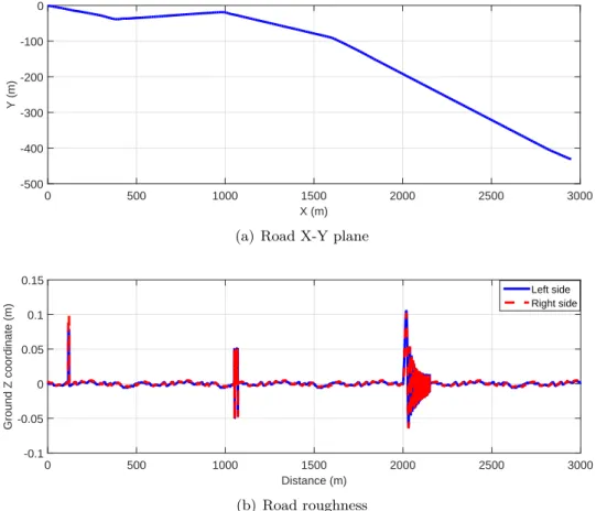
Several road adaptation methods are presented with different approaches, where both longitudinal and vertical dynamics of the vehicle are taken into account. The speed is designed based on the road section, road information and road speed limit, while this speed is fed to the road adaptation algorithm. The LPV-based adaptive semi-active suspension controller calculates the damper force for each corner of the vehicle.
Simulation of Integrated Control Designs
The result of the cloud-based road consideration can be seen in Figure 3.13, which shows the scheduling variable ρ for the adaptive LPV controller and the nominal controller. Vehicle stability is defined as the value of suspension deflection and the result of this performance is shown in Figure 3.24. The designed planning variable using the FLC method is shown in Figure 3.29, while these results are also shown in Table 3.2.
Thesis 1 (Conclusion)
The performance mode is based on the calculation of the performance index, which was also introduced in the mathematical methods (Basargan et al. [2022d]). Multiple faults can occur for the MR dampers, and these faults can adversely affect the operation of the suspension system. The loss of oil through evaporation is for the wear of the damper under extreme operations.
Fault-Tolerant Control Design
As shown in the figure, the damping force decreases by reducing the planning variable ρ. According to our approach, the change in the planning variable in the healthy damper is calculated as the difference;. R calculated from fault reconfiguration is fed to the semi-active controller, while in the first time step, ρ is chosen as 0.745.
Simulation of Fault-Tolerant Control
The RMS value of the roll angle in the faulted scenario is 0.0084, while this value is 0.0063 in the fault-tolerant case. For example, as shown in Figure 4.9, the deflection of the healthy front right suspension is also reduced by the proposed fault-tolerant method. In contrast, the RMS value of the suspension deflection in the uncompensated fault scenario is 0.03; the proposed fault-tolerant controller is reduced to 0.0275.
Thesis 2 (Conclusion)
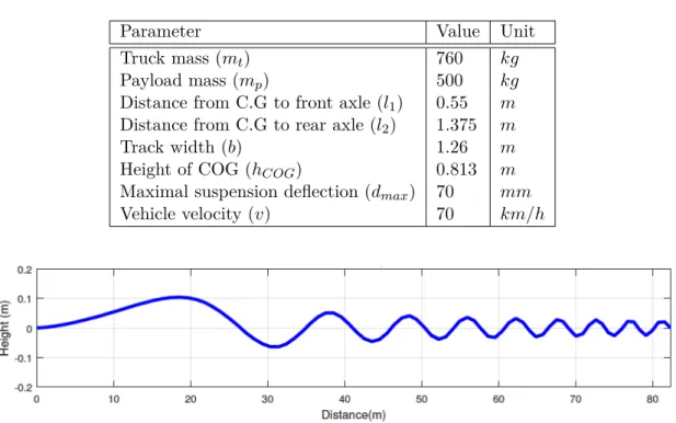
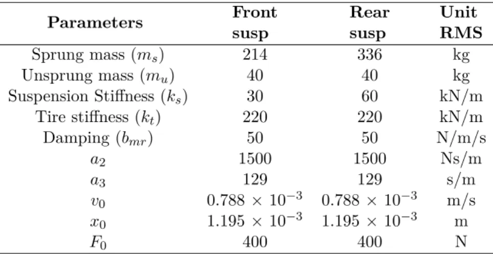
A simulation was performed to see the effectiveness of the proposed task. In the same way, the improvement in tire deformation and damping force is 7.2% and 5.5%, respectively. Table 2.2 shows the nominal parameters of the MR damper (Nino-Juarez et al. [2008]) and the quarter car model for the front and rear suspensions.
LPV Control Synthesis
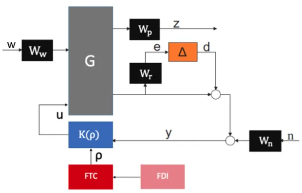
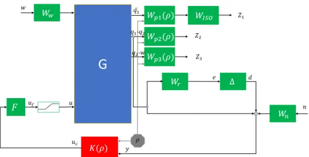
A closed-loop architecture of the introduced LPV-based controller based on a weighting strategy is shown in Figure 5.1. The uncertainties of the model are also considered and indicated by the Wr weighting function and . If driving comfort is preferred, the planning variable is chosen as ρ = 1 , while if it is favored by vehicle handling and stability, the planning variable is ρ = 0 in the designed controller.
Simulation of Adaptive Semi-active Suspension Control
Demonstration of the proposed adaptive semi-active suspension controller was also simulated in the TruckSim environment. For example, the tire deformation of the comfort-oriented suspension setting shown in Figure 5.8a is slightly greater than that of the stability-oriented setting shown in Figure 5.8b. As Figure 5-13 shows, with the comfort-oriented setting of ρ= 1, the vertical acceleration of the simulated vehicle is greatly reduced, which corresponds to the improved driving comfort of the vehicle.
Thesis 3 (Conclusion)
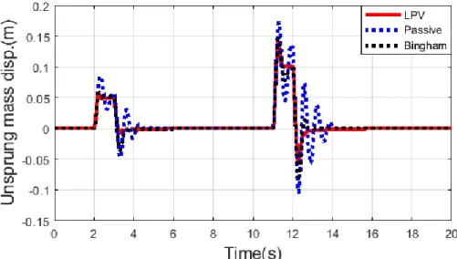
The proposed adaptive semi-active suspension controller is compared with passive suspension and the Bingham model with Simulink simulation. New online reconfigurable road adaptive semi-active suspension controller is designed to handle the non-linear effects and solve the dissipativity and input saturation problem. Another online reconfigurable road-adapted semi-active suspension controller has been designed where the handling of the non-linear effects is achieved.
Future Research Directions
Integrated multi-criteria speed and semi-active suspension control based on look ahead road information. Fault detection and fault-tolerant control of the vehicle's semi-active suspension system with magneto-rheological damper. An lpv error-tolerant control for semi-active suspension scheduled by error estimation.IFAC-PapersOnLine.
State Space Solutions to the Standard H ∞ Control Problem
The solvability of the output feedback H∞control problem is based on two quantities, which are linked to the full information (FI) and the full control (FC) problems. The complete control problem is dual to the complete information case, i.e. the plant has the same form as the conversion of the FI case:. The H∞ solution contains two Hamiltonian matrices, i.e. the FI problem leads to the matrix H and the FC problem leads to the matrix J.:.
The Analysis and Design of LP V Systems
The Analysis of LP V Systems
For an LP V system, function A is parametrically-dependently stable, then the system is a parametrically-dependently stable LP V system. The following lemma establishes the existence of a finite upper bound for the induced L2 norm over the set of all causal linear operators described by a parametrically dependent stable LP V system. The L2 norm level of an LP V system represents the largest ratio of disturbance norm to performance norm over the set of all causal linear operators described by the LP V system.
The Control of LP V Systems with Induced L 2 -norm Performance 124
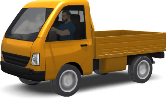
Running the simulation can already be done using the file package received from TruckSim, while TruckSim creates an animation of the vehicle and its surroundings. Some powertrain components can be varied depending on the type of truck, such as the number and arrangement of drive wheels. In the case of the braking system, the proportions of individual elements of the system can be set; the type of braking system (air brake, hydraulic brake), as well as the TruckSim itself, contains a built-in ABS system (which can also be replaced with its own).
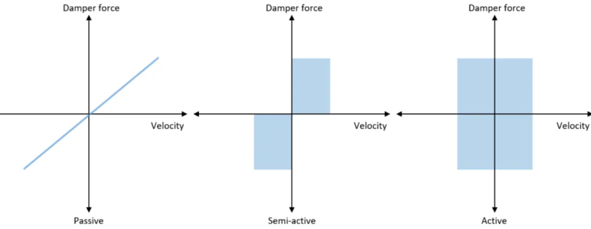
![Figure 1.3: Force–deflection velocity characteristic of MR damper (Rossi et al. [2018]).](https://thumb-eu.123doks.com/thumbv2/9dokorg/2498191.294451/13.892.263.629.153.387/figure-force-deflection-velocity-characteristic-mr-damper-rossi.webp)