An assessment of the overall picture of risk based on all aspects of ageing, taking into account risk reduction measures. Establishing a reliable estimate of the material degradation of the critical SSC caused by the degradation mechanisms associated with the given SSC.
Background
Objectives
Structure of report
Appendices B and C provide a summary of relevant findings from the literature review and a list of documents reviewed, respectively. Appendices F and G provide an example of an LE assessment approach related to material degradation and provide examples of wells and topside process equipment.
Limitations and assumptions
We then describe the key tasks of the LE process, including screening, data collection, challenge identification, analysis, risk reduction measures, and an overall LE management plan.
Categorisation of ageing management issues
Part of the aging management and LE assessment is the performance of analyzes to identify potential deviations of equipment, organization and human resources, in terms of the ability to satisfy all future demands and requirements. In the following sections, we will present the framework for the LE process; based in part on the literature presented in Appendix B.
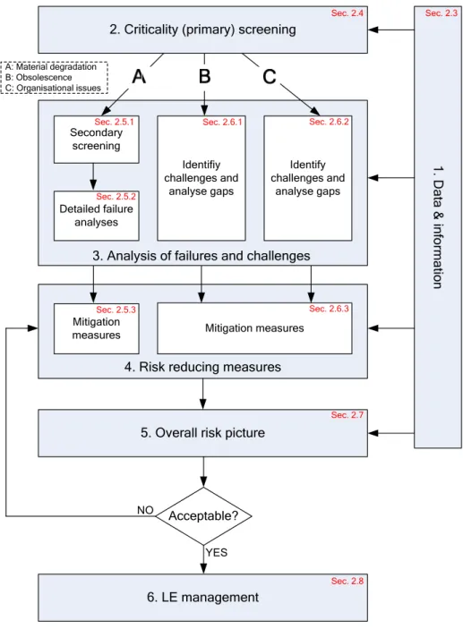
Main tasks of a Life Extension process
Note also that the overall risk picture (activity 5) may result in the introduction of additional risk mitigation measures (ie return to activity 4). One of the major differences is in the operating conditions, which remain more or less constant for the nuclear industry.
Data and information collection
System breakdown and criticality (primary) screening
System breakdown structure
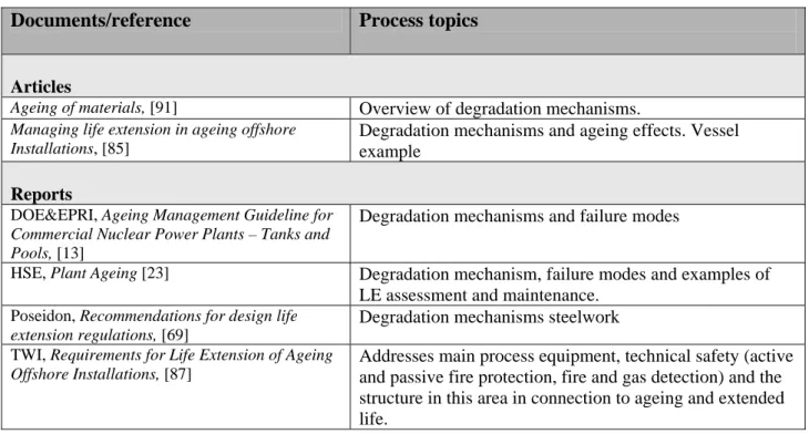
Main systems on a facility
Criticality classification and primary screening
Therefore, in screening SSC for aging components it is questionable whether redundancy should be considered. Should the failure of a system or structure - directly or indirectly - lead to the loss or impairment of a safety function.
Secondary screening and detailed analysis for material degradation
Secondary screening
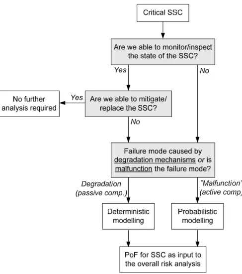
The model can be continuously updated, based on real data, from which we can decide when the SSC needs to be replaced/modified etc. The SSC which we can repair/replace but cannot inspect, (we will not know in advance what the effect is) of any maintenance action); e.g.
Models for detailed analyses
For such an SSC we need to provide a model to predict degradation/reliability for the entire LE period. For such SSC we are completely dependent on models to predict degradation/reliability and make decisions.
Risk reducing measures with respect to physical ageing
Also for these SSCs models to predict degradation/reliability can be continuously updated.
Obsolescence and operational/organisational challenges
Identification of obsolescence challenges
Identification of organisational and human resources challenges
Analyses to resolve identified challenges
Overall risk picture (for the LE period)
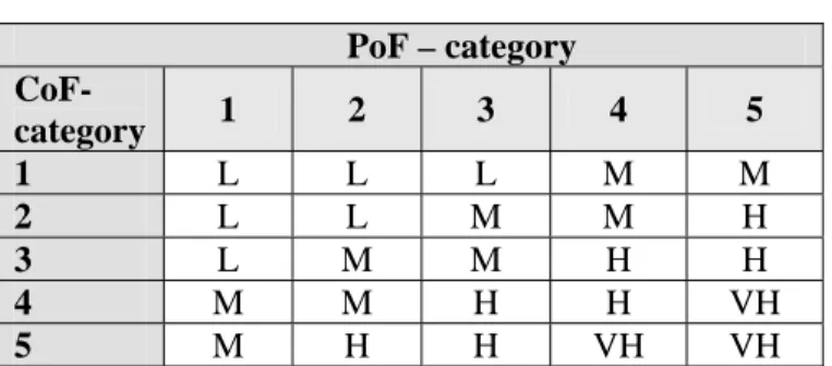
Risk is given as a combination of the probability of failure (PoF) and the consequence of failure (CoF), and we can use a risk matrix to describe the risk associated with failure of various systems. Based on the risk assessment, it must be decided whether LE is feasible for the facility (with the proposed risk reduction measures).
LE management plan
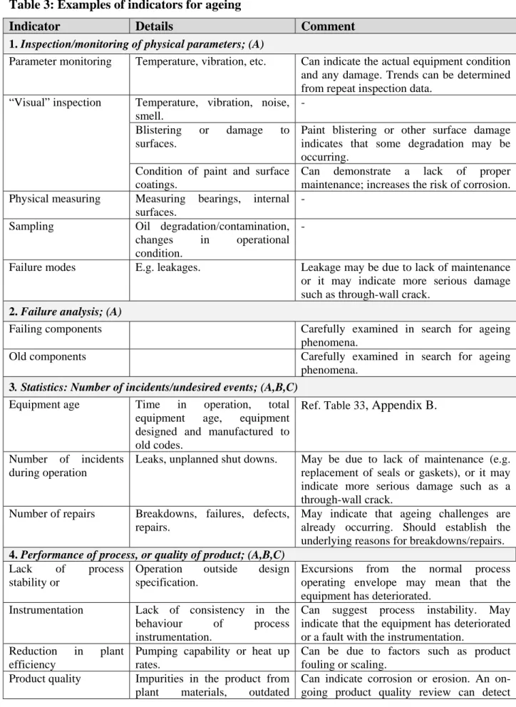
Indicators of ageing
Leakage can be due to lack of maintenance, or it can indicate more serious damage such as cracks in the wall. May be due to lack of maintenance (e.g. replacement of seals or gaskets) or it may indicate more serious damage such as a crack in the wall.
Uncertainties related to LE
Lack of awareness of the possible aging challenges, including all degradation mechanisms, failure modes, obsolescence challenges and organizational problems. Some of the following discussions will distinguish between active and passive SSC; therefore a brief introduction to these concepts is given.
Assessment of physical state
- Degradation mechanisms
- Failure modes
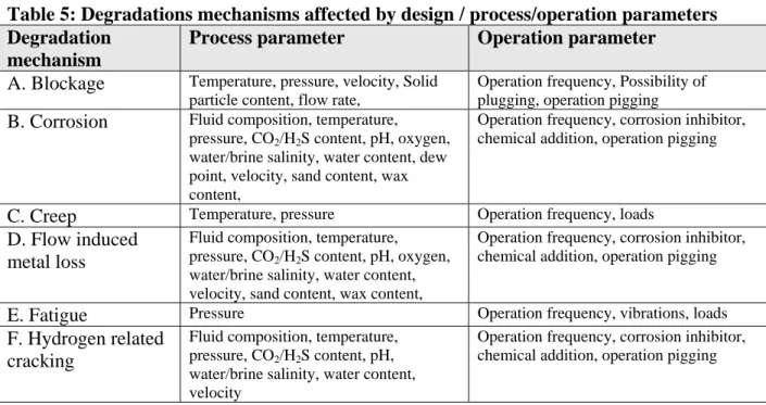
- Process parameters and operational conditions
- Information required to assess state of degradation
Flow Loss (I) – Mechanical removal of material from a surface as a result of relative motion or impact of solids, liquids or vapors. Rapid pressure change (rise or fall) (III) – Changes in pressure due to changes in operation.

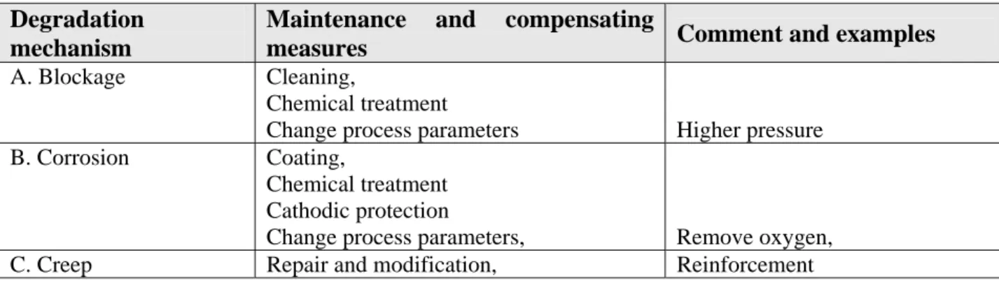
Maintenance and compensating measures
Detection
During the life extension period, there may be changes to the operating conditions that may have a significant impact on the technical integrity of the facilities, e.g. Corrosion tubes/Internal: (in-service) testing, Eddy Current testing General/External: Visual inspection, ultrasonic testing, penetrant testing.
Monitoring
Maintenance and compensating measures
Optimized inspection, monitoring and/or testing (both with respect to type and frequency of inspection/testing). Corrosion Optimized inspection, monitoring and/or testing, periodic evaluation of operating experience, design changes, replacement and/or repair.
Screening to analyse material degradation
Fatigue Optimized inspection, monitoring and/or testing, periodic review of operational experience, design changes, replacement and/or repair. Generally, topside equipment is accessible and can be inspected and/or repaired, while subsea equipment is more difficult and expensive to inspect and repair, and some subsea equipment is not even replaceable.
Models for ageing
Analysis of physical degradation
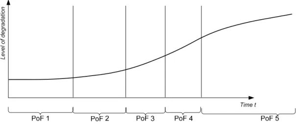
To understand the process from initial defect to propagation, to detect defects and predict their evolution, it is necessary to identify the degradation mechanism at work and to have a precise knowledge of the physical phenomena and the physical or statistical laws of degradation associated with the mechanism. , [15]. Figure 10 shows the model for the degradation rate. Some of these models may have a probabilistic aspect, but are based on a physical understanding of the process.
![Figure 10: Evolution of level of degradation [15]](https://thumb-eu.123doks.com/thumbv2/9pdfnet/19450751.0/48.892.229.692.461.679/figure-10-evolution-level-degradation-15.webp)
Probabilistic modelling
This is the average failure rate of a group of components that have been in operation for a period of t (without giving the exact history of a particular component in terms of failures/repairs). Assuming so-called "minimum repair", this means that the ROCOF will actually follow the failure rate (danger) of the new component.

Covariates
Examples of the use of these types of models, using actual offshore data, are e.g. Finally, [86] presented the use of Markov decision models in aging, which represents a fairly sophisticated approach.
Summary on LE assessment with respect to material degradation
Challenges and possible lack of knowledge
Do we have sufficient knowledge and models for the effect of maintenance on the degradation process. The relevance of these questions may depend on the actual systems and how accessible they are to assess their current state.
Overview of possible challenges
Also, material degradation analyzes (A) can provide useful data for analyzes of aspects B and C.
Obsolescence
There must also be procedures to provide the necessary technical support and an adequate supply of spare parts. Small populations of different types of equipment cause relatively high costs for maintaining knowledge and spare parts.
Human resources and organisational issues
Analyses and risk reducing measures
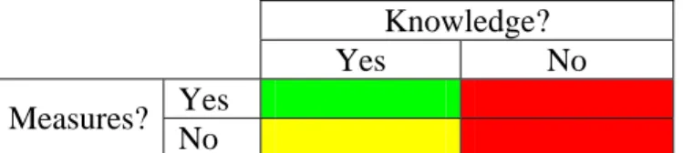
It is therefore important to also take the time perspective into account when evaluating the compensatory measures. The gap assessment may also indicate that it may not be worth making changes due to the risk and/or cost of implementation.
![Figure 15: Methodology for performing the gap analysis, based on [60]](https://thumb-eu.123doks.com/thumbv2/9pdfnet/19450751.0/61.892.117.825.118.399/figure-15-methodology-performing-gap-analysis-based-60.webp)
Examples: Emergency preparedness and other HSE issues
Challenges with respect to obsolescence and operational issues
Introduction
Material handling system and overall requirements
Changes of platform layout
Do the new modules or equipment introduce new hazardous areas that affect boom movement or in terms of consequences for dropped objects. In general, sleeping areas must be designed so that all equipment in the area can be lifted in a safe manner.
Obsolescence
Information on the extension and weight capacity of working and lying areas must be available at the operator's place of cranes [48]. The structure of lay-down areas must be checked for accidental damage limit states due to impacts from dropped objects in accordance with NORSOK N-004.
Organisational and human issues
Crane load
Further HSE issues
Working environment
The health, safety and ergonomics requirements for the crane operator will most likely be the problem of the cabin of the old cranes (visibility, communication, noise, vibration and air conditioning).
Lifting/evacuation of personnel
Environmental issues
Requirements and safety measures
- Risk and reliability analyses
- Safety requirements
- Operational limitations/conditions for cranes
- Regulations and standards
Annex A to NS-EN also provides a selection of a suitable set of crane standards for a given application. Annex ZA of [55] also informs about the relationship between this European Standard and the essential safety requirements of EU Directive 98/37/EC, amended by Directive 98/79/EC.
Summary of concerns related to material handling
Corrosion of the conductor and surface jacket can propagate into the well barrier elements if not stopped. In particular, the most relevant degradation mechanisms for each part of the system (barrier element) are highlighted.
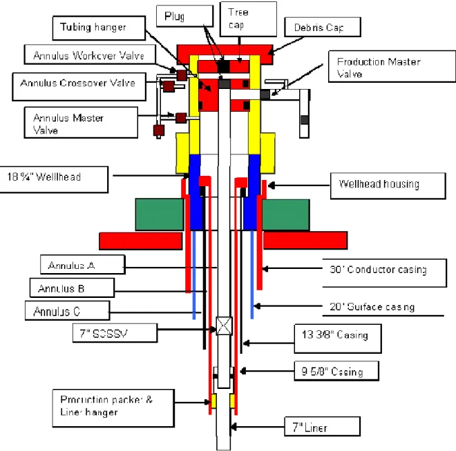
System description
Well barrier elements barriers
In evaluating aging and life extension of wells, an example used the well barrier and the well barrier scheme as defined in NORSOK D-010, [46].
Literature review with respect to wells
System specific degradation mechanisms and failure modes
Normally the conductor jacket is installed 50 – 100 m below the seabed, depending on the seabed conditions. Additional stress in the conductor and surface housing may occur due to loss of guide plates, etc.
System specific LE assessment
Increasing the wall thickness in the upper part of the casing below the subsea wellhead can improve the fatigue life of the well. Operating restrictions for the well should also be included in the well transfer documentation package.
Maintenance & ageing related to wells
Below are some good considerations regarding fatigue, foundation and settlement, structural degradation/capacity and design and construction variations. As-build wells should be compared to design to check for any stress increases that may have been missed – (welded systems, welded attachment, etc.).
Life Extension assessment – wells and drilling
- Requirements and issues for the LE assessment
- Required information on design, materials and operation
- Evaluation of ageing mechanisms and failure modes
- Maintenance and modification for wells
Repair and/or replacement of components or the complete casing and/or production string with accessories is a possible outcome for the well completion system. Pressure testing is often used to verify recovery of well completion system and to verify that the component meets the defined pressure requirement.

Challenges and lack of knowledge
The output from the LE analysis can also be an update to the maintenance program. This data can then be used to estimate the loads in the critical zone of the conductor and the surface layer below the wellhead.
Subsea system overview
Pipelines
The most important degradation mechanisms for each part of the system are particularly emphasized, i.e. The formation of hydrates and waxes in subsea flows will cause undesirable fluid properties and even block the flow of the well, which means shutdown and comprehensive remediation.
Risers
Various types of equipment such as monitoring devices, valves, slug arresters, pig launchers and pig receivers are installed at the pipeline terminations. Pipelines carrying aggressive compounds such as hydrogen sulphide (H2S) or CO2 are sometimes made of stainless steel alloys, e.g.
Subsea production systems
Literature review with respect to pipelines
- Standards
- System specific degradation mechanisms and failure modes
- System specific LE assessment
- Maintenance & ageing related to subsea pipelines
As a major consequence, the planned lifetime of the cathodic protection system may be shortened and thus lead to insufficient protection of the pipeline system. With the publication of the latest revisions of cathodic protection standards DNV, ISO and.
![Figure 21: Flowchart detailing pipeline life extension process [44]](https://thumb-eu.123doks.com/thumbv2/9pdfnet/19450751.0/91.892.120.811.122.991/figure-21-flowchart-detailing-pipeline-life-extension-process.webp)
Literature review with respect to flexible risers
- Standards etc
- System specific degradation mechanisms and failure modes
- Barrier degradation mechanisms and failure modes
- System specific LE assessment
- Maintenance & ageing related to flexible risers
Fatigue or carcass wear damage has not been reported in the open literature. However, no fatigue failures of the outer casing have been reported due to normal operating conditions.
![Figure 23: UKOOA statistics on riser operational failures, UK + Norway [75]](https://thumb-eu.123doks.com/thumbv2/9pdfnet/19450751.0/96.892.176.770.196.665/figure-ukooa-statistics-riser-operational-failures-uk-norway.webp)
Literature review with respect to Subsea Production Systems
System specific degradation mechanisms and failure modes
Wet installation of a rigid steel clamp to strengthen pipes and seal the outer casing by divers. Breakdown of the steering system occurs due to wear, exposure to seawater and well fluids, high temperatures, hydraulic fluids, etc.
System specific LE assessment
A number of activities have been carried out to gain an understanding of the failure mechanisms of components made from such materials. When the metallic pipe material is exposed to seawater (i.e. deteriorated insulation) and the CP is insufficient, it will result in accelerated degradation of the pipe [8].
Maintenance & ageing related to subsea production systems
Over time, failures of power and signal transmission cables may occur due to migration of water through insulation, etc. Damage to the coating, both due to general degradation and due to contact with fishing gear.
Life Extension assessment
Information on design, materials and operation
Evaluation of ageing mechanisms and failure modes
Maintenance for pipelines, riser and subsea equipment
Challenges and lack of knowledge
In particular, we point out the most important degradation mechanisms for each part of the system, i.e.
System description
Inlet – from wells through flowlines and manifold and to inlet of 1st stage separator (including test separator and heater) [System 16]. 2nd stage separator – oil/gas line from inlet 2nd stage separator to heater/cooler on crude oil/gas line [System 20].

Literature review with respect to process equipment
- Standards
- System specific degradation mechanisms and failure modes
- System specific LE assessment
- Maintenance & ageing related to topside process equipment
Produced water – water from Test Separator, 1st Stage Separator, 2nd Stage Separator and Gas Treatment System and for seawater injection or disposal including all equipment [System 44]. Gas treatment system – gas from Test separator, 1st Stage Separator and 2nd Stage Separator through the entire system, ending at gas injection and/or export [System.
Life Extension assessment – Topside process equipment
Information on design, materials and operation
Pipes and ductwork are, statistically, the source of the most leaks and loss of containment in systems containing hazardous fluids or pressure. In addition, it is important to make information available about process and operating parameters as described in section 3.1.3.

Evaluation of ageing mechanisms and failure modes
Maintenance for topside process systems
Pressure testing is often used to verify the repair of the piping system and to verify that the component meets the defined pressure requirement.
Challenges and lack of knowledge
First, a description and breakdown of the system (from the point of view of barriers) is given. In particular, we point out the most important degradation mechanisms for each part of the system (barrier element), and see how the general results of Chapter 2 can be applied.
System description
PCS is particularly important to reduce the number of requirements for "real" safety systems such as PSD, ESD and FGD. Note that we include the PC system here as a "barrier"; as this is important for the number of requests for security systems.
Literature review: LE for safety systems
- Standards (safety systems)
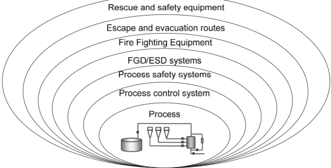
- Degradation mechanisms for safety related equipment
- Failure modes
- LE assessment for safety systems
- Maintenance & ageing related to safety systems
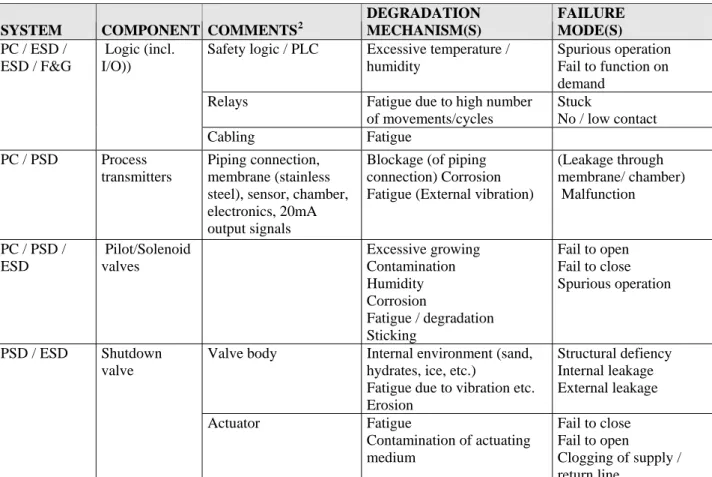
Reduced ESD system capacity due to aging processes (eg valve corrosion) Fire and. Reduce the risk of fire escalation by protecting the facility from fire with an active protection system.
![Table 29 below lists degradation mechanisms and failure modes for different barriers and barrier function according to [87]](https://thumb-eu.123doks.com/thumbv2/9pdfnet/19450751.0/124.892.211.833.461.913/degradation-mechanisms-failure-different-barriers-barrier-function-according.webp)
Life Extension assessment for safety systems
Life Extension Case: Process safety systems
Note that for safety assessment it is sufficient to distinguish between Safe (false operation) and Dangerous (fails to operate on demand) failure modes for safety systems; EG Note that in the analysis of safety systems we should include in the analysis the "rate of demand" and PFD ("Probability of failure on demand") instead of PoF.
General information
It is a specific feature of the safety systems that they represent barriers to major dangerous events such as fires and explosions (reducing probability and/or consequence). The ability to determine the state and also replace devices if necessary is generally quite high for (modules of) the safety systems.
Challenges and lack of knowledge
General tasks and challenges for the LE process
Determine which indicators you want to apply in the LE period to identify the level of degradation. Ensure sufficient competence to carry out and monitor the LE process during the LE period.
Concerns and possible challenges for specific systems
Lack of knowledge of fatigue and fatigue models, especially fatigue of subsea wellhead and Christmas. Lack of knowledge of wear and wear models (production line wear due to rotating production string for rig and subsea wells and riser wear for subsea wells due to drill string rotation).
Knowledge gaps related to ageing
In aging facilities, it is a concern that the probability of failure of multiple components increases; so multiple components can fail simultaneously resulting in multiple site failures.
Further research and development
24] IAEA, Methodology for the Management of Aging of Nuclear Power Plant Components Important to Safety, IAEA, 1992. 75] Saunders Chis et.al., A Systematic Assessment of Thrulife Integrity Management and Life Extension of Deepwater Subsea Systems, OTC.
Definitions
Failure - the state of an object characterized by the inability to perform the required function, except for inability during preventive maintenance or other planned actions or due to lack of external resources, [51]. Life Improvement - Methods/procedures to obtain acceptable technical and operational integrity throughout the extended life.
Abbreviations and Acronyms
Non-Destructive Testing (NDT): A process that involves testing any material, component or assembly by means that do not affect its ultimate utility [23]. IASCC - Irradiation Assisted Stress Corrosion Cracking IGSCC - Intercrystalline Stress Corrosion Cracking I&M - Inspection and Monitoring.
Ageing management
On the other hand, age-related degradation of passive components may not be as easily detectable as for active components, as the SSC appears to function normally until it fails. The definition of active and passive components can be adjusted when applied to offshore installations.
![Table 31: The two concepts of ageing (ESReDA, 2006), [15]](https://thumb-eu.123doks.com/thumbv2/9pdfnet/19450751.0/148.892.114.835.178.626/table-31-concepts-ageing-esreda-2006-15.webp)
Life extension assessment
Determining the end of the expected life (based on the planned life or at least 20 years). Items 1, 4, 5 and 6 in the list above point to important (operational) SSC information to be collected in the LE process.
![Figure 29: Process diagram, establishing maintenance program (NORSOK Z-008, [51]) Long Term Safety Review (LTSR)](https://thumb-eu.123doks.com/thumbv2/9pdfnet/19450751.0/152.892.120.823.364.891/figure-process-diagram-establishing-maintenance-program-norsok-safety.webp)
Maintenance management
Maintenance and ageing
For example, increase in temperature or pressure may be an indication of accumulation of corrosion products in the tubing of a heat exchanger, and instrument drift may be an indication of electronic component degradation. Damage to coatings not reinstated Underlying material exposed to harmful environment Equipment modification Design may be outside original limitations.
System breakdown and screening
When equipment is modified, repaired or when there is a change in operating conditions, it is necessary to consider the impact of the change on the safety of the equipment and system, [23]. If the error/fault affects more than one of the areas being evaluated, this should also be described so that it is clear from the text how the effect occurs.
![Figure 33: Illustration of equipment hierarchy; NORSOK Z-008, [51]](https://thumb-eu.123doks.com/thumbv2/9pdfnet/19450751.0/161.892.118.832.161.564/figure-33-illustration-equipment-hierarchy-norsok-z-008.webp)
Physical state of SSC
We can define an aging indicator as a sign or evidence that damage has already occurred or is about to occur, and can be thought of as symptoms of aging damage. Here [23] defines an indicator of aging as a sign or evidence that a damage has already occurred or is about to occur, and can be perceived as symptoms of aging damage.
![Figure 36: Relationship between failure cause, failure mechanism, failure mode and failure effect, [72]](https://thumb-eu.123doks.com/thumbv2/9pdfnet/19450751.0/164.892.127.832.281.662/figure-relationship-failure-failure-mechanism-failure-failure-effect.webp)
Hazards and undesired events
Instrument failure - general Continuous condition monitoring Instrument failure - general Periodic preventive maintenance Mechanical failure - general Functional testing. Mechanical failure - general Continuous condition monitoring External leakage - Utility medium Instrument failure - general Accidental observation.
![Table 38: Undesired events stressing ageing [25]](https://thumb-eu.123doks.com/thumbv2/9pdfnet/19450751.0/170.892.105.841.317.458/table-38-undesired-events-stressing-ageing-25.webp)
![Figure 2: Aspects of ageing management, based on [15]](https://thumb-eu.123doks.com/thumbv2/9pdfnet/19450751.0/15.892.157.789.200.512/figure-2-aspects-ageing-management-based-15.webp)
![Figure 6 shows the kind of information necessary for the evaluation of ageing and safety importance of components (from [15])](https://thumb-eu.123doks.com/thumbv2/9pdfnet/19450751.0/39.892.122.824.475.853/figure-information-necessary-evaluation-ageing-safety-importance-components.webp)