Source: Norskpetroleum.no ..5 Figure 2 Edited graph of the Gjøa P1 project organization for drilling, wells and. At this time, the well had been drilled to total depth (TD) in the 12 ¼-inch section, a few feet into the top of the reservoir.
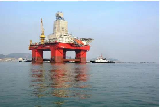
Description of organisation and facility
Neptune
Odfjell
Equipment involved
Continuous circulation system (CCS)
Drill pipe
Experience from these and other nearby wells played a key role in the detailed planning of the G-4 H well. If the incident had been prolonged, the properties of the static mud in the well could have changed.
Blowout preventer (BOP)
Position before the incident
Well planning and design
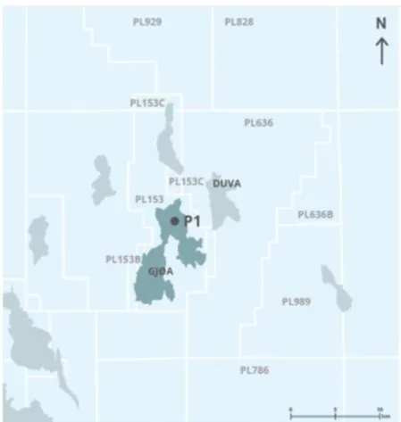
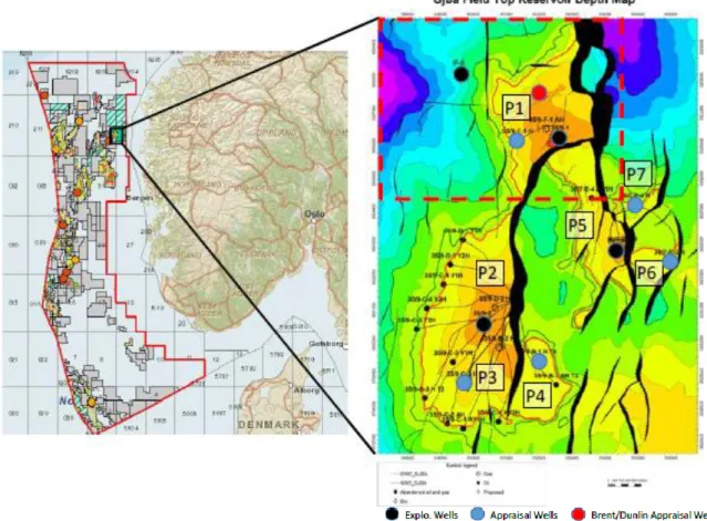
Furthermore, it was specified that the recommended practice for the angle of the manhole in the cover was a maximum slope of 55°. Unstable formations were flagged as a geologic hazard in the 12 ¼-inch section, with such consequences as collapse, stuck strand, and engineering derailment. The first operational phase in the development of the Gjøa P1 structure was completed in the spring and summer of 2020 with the drilling of appraisal wells 35/9-15 S/15 A and 35/9-15 BT2.
The G-4 H well was planned with a standard four-string casing design at the top of the reservoir. Plans called for the 13 3/8-inch x 13 5/8-inch casing to be installed at the top of the lower Kyrre Formation, where it was to be cemented with a gas-tight cement up to 200 meters above the casing shoe. Predictions indicated a zone of +/- 450 meters with a weak formation in the upper part of the section and another of +/- 60 meters just above the reservoir with significant collapse pressure.
Maximum pore pressure for the section was predicted as 1.03 sg, a minimum fracturing pressure of 1.27 sg was expected in the weak formation zone and a maximum formation collapse pressure of 1.24 sg was expected in the zone just above the top of the reservoir. The section would be drilled with a standard rotary steerable system (RSS), initially with an oil-based mud of 1.12 sg equivalent static density (ESD) which would be increased to 1.15 sg ESD before drilling the higher collapse formation . Two of the main risks identified for drilling the section were loss of mud in the weak zone and formation collapse with subsequent stuck string in the zone immediately above the reservoir.
Contingency plans
A fortnight before the incident, the 5-inch DPs with CCS submarines were assembled and ready placed in the elevator. The CCS sub-conductors had tool joints with 50 API NC threads, which were torqued to 38 kNm. This introduced a weaker link in the upper part of the drill chain, which otherwise consists of five-inch DPs with NC-50 DSTJ tool joints with a torque of 62 kNm.
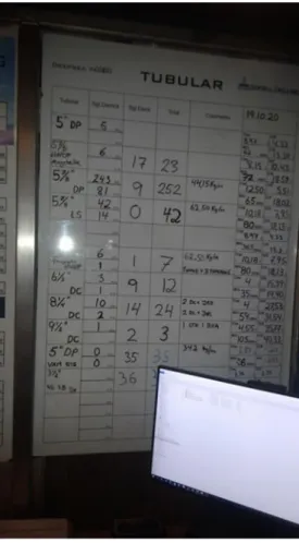
The whiteboard in the driller's control room, which provides a summary of the capacity of the cord components, was not updated with the weaker tool joints on the CCS subhoe. The Norwegian Petroleum Safety Authority (PSA) decided to investigate the incident and a letter announcing this was sent to both companies (Neptune og Odfjell) on 13 October 2020. Three members of the PSA team went offshore from 23-26 October 2020 and conducted interviews with relevant personnel as well as inspection of the drilling area.
The Covid 19 position requires adaptation, and Neptune organize interviews with staff on land using suitable premises in the Quality Hotel Pond on Forus.
Course of events
This will compensate for stopping pumping while the string is ejecting and therefore not gaining the extra downhole pressure created by the CCS during drilling. Mud weight was increased from 1.10 sg to 1.11 sg before the string started to push out with the help of a little lubrication. It soon became clear that the rope was held back to some extent by the formations or by accumulated cuttings.
Attempts were made overnight to move the rope and pump mud in an attempt to improve the position in the borehole. The problems in the well worsened on the morning of September 20, 2020 and the string appeared to be more or less stuck, while circulation options were variable. When the free portion of the wire was pulled to the drill floor, the .
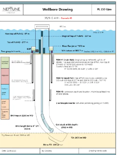
It was then suspected that the string had split at several points and that one or more of its sections had fallen towards and into the BOP. It eventually became clear that at least one of the tool links split further down the string had spun/twisted off between DPs beyond the top cut from a CCS sub tool assembly. With two or more DPs through the BOP, neither pipe rammers nor the annular fuses could tighten around the string.

Normalisation after the incident
An assessment of the geometries in the BOP, wellhead, and upper casing revealed that it was highly likely that two or more DP sections were trapped in the BOP. The well would be open to the seabed via the BOP, but only one. With this insight into the situation, a successful sliding test was carried out by NOV in Houston on September 25, 2020 with three DPs in a similar sliding ram.
Complete barrier testing of the cement plugs was not possible, but they were pressure tested to the extent possible. The tests that could be performed produced satisfactory results, and a planned disconnection of the BOP was performed at a later point in the operations on the well. It landed inside the 13 3/8-inch casing and floated with great force past five tackle connections on fish number one.
With each tool link passed by the lowest link on fish number two, the 13 5/8-inch casing was expanded and rolled into an oval shape. The second fish was found to have drifted 45 meters below the wellhead into the 13 5/8-inch casing. After normalizing the incident, the 13 5/8-inch casing was pulled out before drilling a sidetrack from the well below the 20-inch casing.
Actual consequences
Potential consequences
The established procedure for work in the red zone could cause personal injury in the event of leaks in the CCS submarines. That increased the risk of personal injury because personnel could be forced to work on a pressurized system in the red zone of the drill floor.
Direct causese
Mud weight lower than the formation’s estimated
The procedure required losers to plug a possible leak in a CCS submarine with sledgehammers. In reality, considerably more attention was paid to avoiding loss in the higher formations than to maintaining sufficient mud weight to prevent hole collapse in the lower parts of the section. Interviews revealed this to be a clear reason why the purpose of using the CCS during drilling seemed to have been partly forgotten, and why the mud weight was not increased to the value described in the drilling program and the guidelines for the drilling section.
Several interviewees also claimed that misunderstandings prevailed about the specific requirements for mud weight prior to drawing the line at TD.
Drillstring above BOP composed of joints with
Torque on joints was exceeded
Underlying causes
Experience transfer from earlier wells on Gjøa
The selected well design provided a very narrow drilling window between the expected collapse pressure in the deeper formations and the potential loss zones higher in the same section. The contingency plan in the well design, with an expanding liner to isolate the weak zone from possible collapse zones deeper in the same section, was probably not as ready to mobilize as the plan suggested. Few of those with key roles in the drilling operation had experience from previously drilled wells at Gjøa in 2009-12.
The concept selection report of 24 July 2018 identified the threat of collapse in the hole section as one of the main risks. This was covered in both the G-4 well program and hole section instructions - Gjøa P1 35/9 - G-4 H - 12 ¼ inch, and was included in the detailed operational plans for the section. However, it was not given a prominent place in the description of the planned phases of operation for this part of the well.
On the contrary, there were constant descriptions and reminders of upper mud weight limits to avoid loss in higher zones. Specific descriptions of minimum mud weight requirements to prevent hole collapse associated with CCS shut-off and TD shut-off were not clearly presented in the final operating procedures. From the interviews, it was clear that the decisions made in the operational meetings just before the trip about the requirements to increase the mud weight were misunderstood.
Well design
The introduction of CCS during the summer was an attempt to compensate to some extent for the narrow window.
Pressure of time
Given the planned operational measures, the cement runways and the CCS, it was estimated that the emergency solution would not be necessary. Areas for improvement: these concern observations where shortcomings are noted, but insufficient information is available to determine a violation of the regulations.
Nonconformities
- Insufficient use of change management (Neptune)
- Lack of robustness in well planning (Neptune)
- Inadequate processes for experience transfer
- CCS not qualified in accordance with applicable
The investigation found that this window had become narrower than specified in the original design, without these limitations resulting in significant operational adjustments, such as the introduction of an alternative case design. It was clear from the interviews that implementing an alternative case design with an expandable 8 5/8-inch panel would be challenging and fairly unrealistic due to the Covid-19 situation. The experience from the previous well plans regarding the selection of the depth of installation of the protection tube was not sufficiently taken into account.
The information received was not processed and communicated to the relevant users in a timely manner. It emerged from the interviews that the substantial challenges in the previous well meant that there was limited time available to process the experiences from that operation and transfer them into the detailed plans for the G-4 well. The compound torque for the CCS subplot was not worked out and included in the operating procedure or entered into the driller's whiteboard, which indicated string capacities and limitations.
CCS resulted in the need for more red zone work on the drill surface that was not properly evaluated. It is important not to stand in front of the valve opening when hammering. There has been little assessment of the risk of using CCS in relation to hole problems such as jammed string.
Improvement points
New technology was introduced without the criteria for its use being sufficiently developed to meet HSE requirements. The CCS added a number of weak links high up in the string, which were not adequately assessed.