The following is a description of the symbols and messages that appear on the display and their meaning. The controller's main states (power supply present, alarm active and external ON/OFF input status) are displayed to the user through 3 LEDs on the front panel.
Armadio con batteria ad espansione diretta ad un compressore ed una resistenza (ED)
Precision unit with direct expansion battery, one compressor and one heating element (ED)
Connection diagram
Precision units for shelters
Connection diagram4.3 Armadi per shelter
- Connessione di più unità
- Connecting a series of units
- Parametri di programmazione e loro modifica
- Parametri
- Programming parameters and their modification
- Parameters
- B. It is not possible to move directly from one level to another;
The value of the first accessible parameter is displayed on the top right, the parameter code is flashing. The value of the first accessible parameter is then displayed in the upper right corner, and the parameter code flashes.
Important warning
Copying data from the key to the car's EEPROM With the power off from μAC, insert the key (code MAC2KEY000) into the corresponding connector, (see Fig. 5). Pressing the and button together during startup allows the key to be programmed with the car's parameters.
Avvertenza importante
Description and configuration of the parameters Descrizione e configurazione dei parametri
In condensation use mantiene il ventilatore al minimo and sotto il valore espresso da F5. When operating in condensation, the fan is kept at minimum even below the value of F5. When used in condensation, the fan is switched off below the value of F5, with a hysteresis of 0.5 bar for pressure or 1°C for temperature.
0= energizza in deumidificazione / energizza in deumidifica 1= energizza in deumidifica / diseccita in deumidifica 2= relè per allarmi minori (seguire logica parametro HF). 2= relè per allarmi non gravi (seguire la logica del parametro HF) 3= uscita per comando rotazione / uscita per comando rotazione 4= abilita in umidificazione / abilita in umidificazione 5= diseccita in umidificazione / diseccita in umidificazione 6= selezione a 2 bocchette, illuminata in deum. 1= free cooling tramite 0-10V / free cooling con 0-10V 2= free cooling tramite Out3-Out4 / free cooling tramite Out3-Out4 3= free cooling on/off con Out3 /free cooling ON/OFF con Out3 4= condensazione controllo / controllo condensazione.
1= abilitato in allarme per tutti gli allarmi / abilitato in allarme per tutti gli allarmi 2= disabilitato in allarme solo per allarmi gravi. 2= diseccitato in allarme solo per allarmi gravi 3= tensione in allarme solo per allarmi gravi 3= tensione in allarme solo per allarmi gravi.
6.1 = parametri relativi alle sonde 1 Presenza sonda aria esterna B2
6.1 = probe parameters 1 Presence external air probe B2
Se il configurato model tramite il parameter H1 è CW cool/heat, tale set rappresenta il set estivo (show parameter r9). It stabilizes the maximum variation that can be measured by the probes in the program cycle of the machine; in practice, the maximum allowable differences in measurements are approximately between 0.1 and 1.5 units (bar, °C or. °F, depending on the probe and measurement unit) per second. Low values of this parameter make it possible to limit the effect of impulsive-type disturbances.
By changing this parameter, µAC automatically performs the conversion of all the configuration parameters (setpoint, differentials, maximum limits, etc.), except F5 and F6. Note: If the variation from Celsius to Fahrenheit and vice versa is performed by the supervisor, the parameters are not converted (only the value read by the temperature probes and the symbol on the display are changed).
With set point compensation using an external air probe, this value also represents the lower limit for set point deviation (see Figure 26). When compensating the set point using an external air probe, this value also represents the upper limit for the set point deviation (see Figure 26). Constant for compensating the operating set point based on the temperature measured by probe B2 (see Figure 26).
Con compensazione impostata, tramite sonda aria esterna, questo valore rappresenta anche il limite inferiore di oscillazione impostato (vedi Fig. 26). Con compensazione impostata tramite sonda aria esterna, questo valore rappresenta anche il limite superiore di oscillazione impostato (vedi fig. 26). Costante per compensazione del set di lavoro in base alla temperatura misurata dalla sonda B2 (vedi Fig. 26).
Definisce il Set (a temperatura esterna B2) al di sotto del quale parte la compensazione (vedi fig. 26). Questo parametro rappresenta il limite inferiore per la temperatura di mandata al di sotto del quale la serranda del riparo è chiusa.
6. 3 c= compressor management parameters c1 Minimum ON time
6. 3 c= parametri per la gestione del compressore c1 Tempo minimo di On
F= parametri per la gestione delle ventole F1 Modalità funzionamento ventola
I valori 1 o 2 indicano il funzionamento proporzionale del ventilatore di mandata con Hb=0; se invece si applica il taglio di fase al ventilatore del condensatore con Hb= 1 o 2, si verifica il funzionamento descritto nei diagrammi a fine paragrafo. In caso di rottura della sonda condensa B3, il ventilatore viene forzato alla massima velocità (F8), se la temperatura esterna (B2) è superiore a 15°C, se la temperatura è inferiore a 15°C, invece, il la ventola girerà ad una velocità media compresa tra i valori F7 e F8. Per il controllo proporzionale della velocità del ventilatore è necessaria l'installazione della scheda di potenza MCHRTF*0A0.
In questo caso è necessario impostare i parametri F2 e F3 (vedi par. Calcolo della velocità minima e massima") per ottenere rispettivamente la minima e la massima tensione di uscita accettata dal motore utilizzato. F5 Percentuale della banda di regolazione per la velocità minima o temp./pressione velocità minima alla condensazione F6 Percentuale banda di regolazione per velocità massima Nota: Se il parametro specifica una temperatura, questa non viene convertita automaticamente in gradi Fahrenheit al variare del parametro /C (vedi diagrammi a fine paragrafo).
Consente di specificare un valore di velocità superiore al valore minimo, impostato tramite il parametro F2. Permette di specificare un valore di velocità inferiore al valore massimo, impostato tramite il parametro F3.
F= fan management parameters F1 Fan operating mode
Determina il numero di ore di funzionamento del ventilatore al di sopra delle quali viene segnalata la richiesta di manutenzione. Determina il numero di ore di funzionamento del filtro dopo le quali viene segnalata la richiesta di manutenzione. Questo contaore viene incrementato quando il ventilatore è in funzione e quindi assume lo stesso valore di FA fino al primo reset.
Permette di specificare il tempo, in secondi, durante il quale il ventilatore rimane acceso, dopo l'accensione => STANDBY (tastiera, fasce orarie, ingresso digitale, rotazione). Determina il tempo di funzionamento alla massima velocità con i ventilatori accesi, se utilizzato per il controllo di condensazione, per vincere l'inerzia meccanica del motore. Se impostato a 0 la funzione non viene eseguita, cioè i ventilatori vengono attivati alla minima velocità e poi controllati in funzione della temperatura/pressione di condensazione.
Pressing the buttons while viewing this parameter resets the hour counter (only in USER or FACTORY mode) and cancels the maintenance request if activated. Diagrammi di fungiozione del ventilatore di condensazione in macchine di tipo ED o shelter con F1= 2 / Operating diagrams for the condensation fan in ED or shelter machines with F1=2.
P= parametri per la gestione degli allarmi P1 Ritardo allarme di flusso dalla partenza ventilatore
P= alarm management parameters P1 Flow alarm delay from fan start-up
Delta P6 del kit di allarme per bassa temperatura effettiva Delta P7 del kit di allarme per alta temperatura effettiva. Consentono di impostare la soglia di allarme per bassa (Lt) e alta (Ht) temperatura ambiente. Stabilisce la differenza minima tra la temperatura di ritorno (rilevata da B1) e la temperatura di mandata (rilevata da B4) affinché non venga generato l'allarme funzione raffreddamento (At).
P6 Delta of the effective set point for low temperature alarm P7 Delta of the effective set point for high temperature alarm Sets the alarm threshold for low (Lt) and high (Ht) ambient temperature. This value is specified as a difference from the effective set point, taking into account any compensation actions (see parameters /1, rG, rH, Hc). P8 Delta from low humidity alarm set point P9 Delta from high humidity alarm set point.
PA Ritardo allarmi di alta/bassa temperatura/umidità all'accensione Imposta il ritardo nel riconoscimento degli allarmi di alta/bassa temperatura e umidità all'accensione della macchina, cioè al passaggio da STAND-BY => ON. Attiva il preallarme "ht" con differenziale dal gruppo pari a P7/2 e isteresi 1 grado (in questo caso si consiglia di aumentare il valore di P7).
H= parametri generali di configurazione H1 Modello macchina
H= general configuration parameters H1 Machine model
- Gestione valvola del caldo/freddo e serranda
- Heating/cooling valve and damper management If the actuator for the control of heating or cooling is of a three-point
- Deumidifica
- Dehumidification
- Controllo di condensazione
- Funzione di free-cooling
- Condensation control
- Free-cooling function
H6 Operating mode of the 2 "heating" outputs Out 3 / Out4 Defines for ED and CW models (H1=1,2) the type of connected heating actuators. Defines the excursion time for the valve or, if the housing model is selected, the damper. Likewise, if the valve is required to close below 10%, the control closes it completely before returning to the required value position.
1= activate the humidifier control, generation of corresponding alarms and display of the associated symbol. In the shelter configuration, the activation of the dehumidification prevents the opening of the damper for 2 hours. In the latter case, the activation logic follows that of the main alarm relay out 6, determined by the parameter HF.
For direct expansion machines (ED or shelter), output Y2 can be used to control the condensation fans (modules MCHRTF**A0), integrating this function in the regulation of µAC. The compressor alarms and the PA alarm enable opening of the damper independent of the external temperature.
Clock, time bands and alarm log
- Clock Time display
- Time bands
B. The ON status controlled by the time bands is only valid if the machine is first activated from the keypad or the remote input (if
- Orologio, fasce orarie e storico allarmi
- Orologio Visualizzazione ora
- Fasce orarie
B. Lo stato di On da fasce orarie agisce solo se la macchina è attivata da tastiera e da ingresso remoto (se abilitato)
- Storico allarmi
- Alarm log
- Allarmi e segnalazioni
- Tabella allarmi
- Alarms and signals
- Table of alarms
- Segnalazioni di allarme
- Alarm signals
- Segnalazioni di arresto critico
- Machine shut-down signals
- Schede opzionali
- Scheda seriale RS485
- Optional boards
- RS485 serial board
- Schede gestione velocità ventilatori
- Scheda orologio
- Fan speed management board
- Clock board
- Caratteristiche tecniche
- Technical specifications
- Codici degli strumenti e accessori
- Tabella codici
- Instrument and accessory codes
- Table of codes
- Dimensioni
- Dimensions
- Aggiornamento software
- Note per la versione 1.3
- Errata Corrige
- Software updating
- Notes for the 1.3 version
In places where an alarm is not logged, dashes appear in place of the code. At this point, the FACTORY password (177) is required, which, if confirmed with enter, leads to the deletion of the log. The maintenance signals of compressor 1 and/or 2, fan and filter activate the symbol on the screen, the red LED, the buzzer and the alarm relay due to exceeding the hour counter thresholds.
Detected regardless of compressor activation, and causes it to shut down immediately without waiting for the corresponding delay times. The activation of this alarm ensures that all devices are switched off without waiting for the delay times of the compressors and the fan. These alarms are delayed when the controller starts up (or when the standby mode is exited) for a period equal to parameter PA, and for 1 minute when the set threshold is exceeded.
In addition, exceeding the high temperature threshold causes the compressors to start immediately without waiting for the corresponding delay times. This alarm is delayed by starting up the drive (or leaving standby) for a time equal to the PA parameter and 1 minute from the threshold crossing. The code is displayed in the ambient temperature (or hour-minute) field of the LCD.
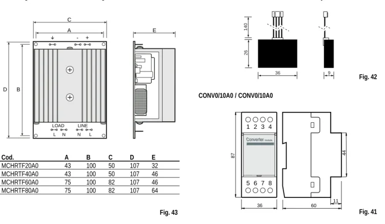
Connect the ground terminal of the MCHRTF**A0 module (where present) to the electrical panel ground.


![The polyfunctionalized enaminone ethyl [(Z)-2-(2,2-dimethyl-4,6-dioxo-1,3-dioxan-5-yl- idenemethyl)-1-methyl-3-oxo-but-1-enylamino]- acetate](data:image/gif;base64,R0lGODlhAQABAIAAAP///wAAACH5BAEAAAAALAAAAAABAAEAAAICRAEAOw==)