Install the unit properly on a surface that can withstand the weight of the unit. If the unit is turned off in the middle of a season, it may result in malfunctions.
1] Read Before Servicing
Check the type of refrigerant used in the system to be serviced
Thoroughly read the safety precautions at the beginning of this manual
Preparing necessary tools: Prepare a set of tools to be used exclusively with each type of refrigerant
Verification of the connecting pipes: Verify the type of refrigerant used for the unit to be moved or replaced
If there is a leak of gaseous refrigerant and the remaining refrigerant is exposed to an open flame, a poisonous gas hydrofluoric acid may form. Keep workplace well ventilated
CAUTION
2] Necessary Tools and Materials
Tools and materials that may be used with R410A with some restrictions
Tools and materials that are used with R22 or R407C that may also be used with R410A
Tools and materials that must not be used with R410A
3] Storage of Piping
Storage location
Sealing the pipe ends
4] Pipe Processing
5] Brazing
Items to be strictly observed
Reasons
Notes
6] Air Tightness Test
7] Vacuum Drying (Evacuation)
- Vacuum pump with a reverse-flow check valve (Photo1)
- Standard of vacuum degree (Photo 2)
- Required precision of vacuum gauge
- Evacuation time
- Procedures for stopping vacuum pump
- Special vacuum drying
- Notes
Apply a vacuum through the high and low side marine gears (CJ1 and 2). Apply a vacuum through the marine gears at the coolant service valve on the high and low pressure side (BV1 and 2).
8] Refrigerant Charging
Reasons
Notes
9] Remedies to be taken in case of a Refrigerant Leak
10] Characteristics of the Conventional and the New Refrigerants
Chemical property
Pressure characteristics
11] Notes on Refrigerating Machine Oil
Refrigerating machine oil in the HFC refrigerant system
Effects of contaminants *1
The effects of contaminants in the refrigerating machine oil on the refrigeration cycle
1] System configuration
Table of compatible indoor units
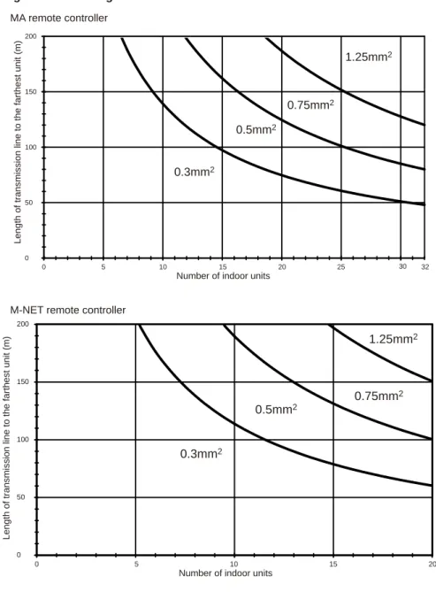
2] Types and Maximum allowable Length of Cables
Wiring work (1) Notes
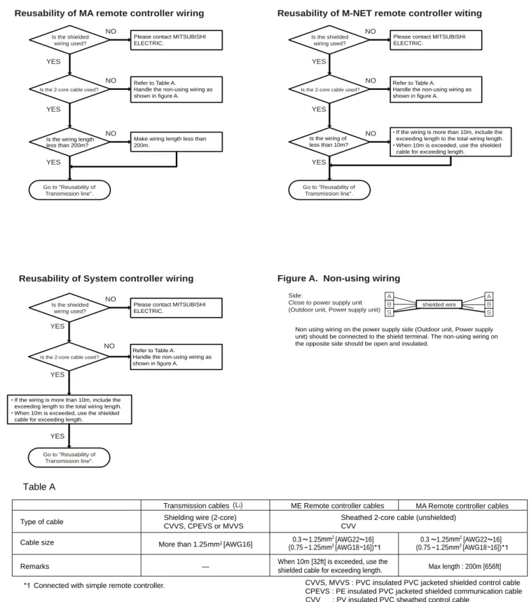
1 MA remote control refers to MA remote control (PAR-20MAA, PAR-21MAA), simple MA remote control and wireless remote control. CVVS, MVVS: PVC insulated, PVC sheathed, shielded control cable CPEVS: PE insulated, PVC sheathed, shielded communication cable Connected with a simple remote control.
3] Switch Settings and Address Settings
Switch setting
M-NET Address settings (1) Address settings table
Turn off signals from the outdoor unit (OC) if there are multiple outdoor units in one system. Low noise mode is valid when Dip SW4-4 on the outdoor unit is set to OFF.
4] Sample System Connection
5] An Example of a System to which an MA Remote Controller is connected
System with one outdoor unit (automatic address setup for both indoor and outdoor units) (1) Sample control wiring
Chain terminals M1 and M2 on the indoor-outdoor transmission line terminal block (TB3) of the outdoor units (OC), on the indoor-outdoor transmission line terminal block (TB02) on the main BC controller (BC ), and of the indoor-outdoor transmission line terminal block (TB5 ) on each indoor unit (IC). Connect terminals 1 and 2 of the terminal block for MA remote control line (TB15) of the indoor unit (IC) to the terminal block of the MA remote control (MA).
- An example of a system with one outdoor unit to which 2 or more LOSSNAY units are connected (manual address setup for both indoor and outdoor units)
- Group operation of units in a system with multiple outdoor units (1) Sample control wiring
- A system in which a system controller is connected to the transmission line for centralized control and which is pow- ered from an outdoor unit
- An example of a system in which a system controller is connected to the indoor-outdoor transmission line (except LM adapter)
- A system with multiple BC controller connections (with a system controller connected to the centralized control line) (1) Sample control wiring
Daisy-chain terminals M1 and M2 of the terminal block for indoor-outdoor transmission line (TB3) on the outdoor units (OC), of the terminal block for indoor-outdoor transmission line (TB02) on the main and sub-BC controllers (BC and BS), and from the indoor-outdoor transmission line terminal block (TB5) on each indoor unit (IC). Daisy-chain terminals M1 and M2 of the indoor-outdoor transmission line terminal block (TB3) on the outdoor units (OC), of the indoor-outdoor transmission line terminal block (TB02) on the main and sub BC controllers (BC and BS), and from the indoor-outdoor transmission line terminal block (TB5) on each indoor unit (IC).
6] An Example of a System to which an ME Remote Controller is connected
In a system with one controller under BC, make the settings for the indoor units in the following order. i) The indoor unit is connected to the main controller BC. ii) Indoor unit to connect to sub controller BC 1. iii) Indoor unit to connect to sub controller BC 2. If the addresses assigned to the main controller BC overlap with any of the addresses assigned to external units or to the BC sub-controller, use a different, unused address within the setting range.
7] An Example of a System to which both MA Remote Controller and ME Remote Controller are connected
Assign an address higher than that of the indoor units connected to the MA remote controller. Assign an address equal to the sum of the smallest address of the indoor units connected to the BC sub-controller and 50.
8] Restrictions on Pipe Length
Determining the reusability of the existing piping
WARNING
Restrictions on pipe length
If the capacity of the connected indoor units is P200 or higher, use the numbers in parentheses as a reference. The maximum total capacity of indoor units that can be connected to BC sub-controller CMB-P1016V-HB1 is P350 or lower.
Refrigerant pipe size
Connecting the BC controller
1] Outdoor Unit Components and Refrigerant Circuit
Refrigerant circuit
High pressure side coolant service valve (BV1) Solenoid valve (SV5b) Solenoid valve block (SV4a, SV4b, SV4c, SV4d).
2] Control Box of the Outdoor Unit
3] Outdoor Unit Circuit Board
- Outdoor unit control board
- M-NET board
- INV board
- Fan board
- Noise Filter
Serial communication signal output GND(INV board) Input 17VDC CN22 GND(INV board) Input 5VDC.
4] BC Controller Components
CMB-P V-GB1, HB1 (1) Front
5] Control Box of the BC Controller
CMB-P1016V-G1, GA1, HA1
6] BC Controller Circuit Board
BC controller circuit board (BC board)
RELAY BOARD (RELAY 4 board)
RELAY BOARD (RELAY 10 board)
1] Functions and Specifications of MA and ME Remote Controllers
Comparison of functions and specifications between MA and ME remote controllers
Remote controller selection criteria
2] Group Settings and Interlock Settings via the ME Remote Controller
Group settings/interlock settings
After completing step , a subsequent press of the [ ] button will bring up the address of another registered device. Display the address of the LOSSNAY unit that was locked with the indoor unit in step. Each press of the [ ] button will show the address of a registered indoor unit and its unit type on the display.
Remote controller function selection via the ME remote controller
When set to "ON", the automatic operation mode is available for selection in the function selection mode. As with Cool/Dry mode, use the [CLOCK-ON-OFF] button and [TIMER SET ( ) or ( )] to set the temperature range. As with Cool/Dry mode, use the [CLOCK-ON-OFF] button and [TIMER SET ( ) or ( )] to set the temperature range. 5 4 3) Temperature range setting for automatic mode.
3] Interlock Settings via the MA Remote Controller
LOSSNAY interlock setting (Make this setting only when necessary.)
4] Using the built-in Temperature Sensor on the Remote Controller
Selecting the position of temperature detection (Factory setting: SW1-1 on the controller board on the indoor unit is set to OFF.)
1] Electrical Wiring Diagram of the Outdoor Unit
2] Electrical Wiring Diagram of the BC Controller
Name Transformer Thermistor sensor Expansion valve Pressure sensor BC circuit controller board Terminal block (for power source) Terminal block (for transmission) Solenoid valve Solenoid valve Terminal fuse AC250V 6.3A F. Symbol explanation) ZNR02ZNR01 LEV1LEV. Name Transformer thermistor sensor Expansion valve Pressure sensor Relay circuit board BC controller Terminal block (for power source) Terminal block (for transmission) Solenoid valve Solenoid valve Terminal fuse AC250V 6.3A F. Name Transformer thermistor sensor expansion BC board expansion sensor BC Terminal block (for power source) Terminal block (for transmission) Solenoid valve Solenoid valve Terminal fuse AC250V 6.3A F.
CMB-P1013,1016V-G1
Never connect a power line to it. 2. The initial set values of the CONT.B switch are as follows.
CMB-P108,1010V-GA1
Transformer Thermistor Sensor Expansion Valve Name BC Circuit Controller Board Terminal Block (for Power Source) Terminal Block (for Transmission) Solenoid Valve Terminal Fuse AC250V 6.3A F. Expansion Valve Name of transformer thermistor sensor Expansion valve circuit relay board BC power board (for power terminal controller) Terminal block (for transmission) Solenoid valve terminal fuse AC250V 6.3A F. Name Transformer Thermistor sensor Expansion valve Circuit board Control relay BC Terminal block (for power source) Terminal block (for transmission) Solenoid valve terminal fuse AC23AV.
3] Electrical Wiring Diagram of Transmission Booster
1] Refrigerant Circuit Diagram
Outdoor unit
BC controller
2] Principal Parts and Functions
Outdoor unit Part
SV5c Allows the coolant to pass through. through the bypass pipe to prevent the accumulation of liquid refrigerant. closed while de-energized. open while SV8 is not powered. It opens or closes as needed during automatic refrigerant charging. closed while de-energized. closed while de-energized. functions) Remarks Use Specifications Verification method.
Indoor Unit Part
BC controller (1) G type
1] Functions and Factory Settings of the Dipswitches
- Outdoor unit (1) Control board
- Function of the switch (Indoor unit) (1) Dipswitches
- Function of the switch <Remote controller>
- Switch functions <BC controller> (Control board)
If both SW1-7 and SW1-8 are set to ON, the fan remains stopped during Thermo-OFF heating. Always set to OFF on PKFY-VBM model units Set to ON (sensor built into remote control) on all fresh (PEFY-VMH-F) model units. The settings in the shaded areas are factory settings. (Refer to table below for factory settings of switches whose factory settings are not indicated by shaded cells.) Always set to Downblow B or C on PKFY-VBM model units.
2] Controlling the Outdoor Unit -1- Outline of Control Method
Rotation speed control of compressor or fan depending on refrigerant pressure value and changing speed. When cooling and heating units coexist, the operation mode (cooling main mode or heating main mode) is determined based on the refrigerant pressure in the R2 refrigerant circuit and speed variation data. 3) Auto cooling/heating operation pattern. When automatic cooling/heating mode is selected from the remote controller functions, the indoor temperature is detected in a pattern as shown in the figure below, and the operation mode (cooling or heating) is selected automatically. 4) Relation between the operating mode and the charging power (kW) (within a system) 1 Cooling mode.
3] Controlling BC Controller
Control of SVM1
Control of LEV
Control of SVM2
GA type
4] Operation Flow Chart
Mode determination flowchart
The system may go into fault mode on either the indoor unit or the outdoor unit side. The system may go into fault mode on either the indoor unit side or the BC controller or outdoor unit side. If the BC controller or the outdoor unit experiences a problem, all the connected units will stop.
Operations in each mode (1) Cooling operation
When the outdoor unit enters defrost mode, defrost command is sent to the BC controller and the indoor units. When the inlet temperature of the indoor unit becomes 18 C [64 F], or less, the fan always runs (at low speed). The outdoor unit, indoor unit and solenoid valve operate in the same way as they do in cooling mode when the compressor is on.
1] Items to be checked before a Test Run
2] Test Run Method
3] Operating Characteristic and Refrigerant Amount
Operating characteristic and refrigerant amount The following table shows items of particular importance
4] Adjusting the Refrigerant Amount
Symptoms
Amount of refrigerant
Amount of refrigerant to be added
5] Refrigerant Amount Adjust Mode
Procedures
Close the valve on the cylinder and disconnect the cylinder. (Note 1) The refrigerant charge is adequate.
6] The following symptoms are normal
7] Standard Operation Data (Reference Data)
Single unit (Standard) (1) Cooling only operation
1] Error Code Lists
Tube temperature at heat exchanger outlet (TH3) O. Distinct only from All-Fresh type indoor units Outdoor unit discharge. fault Heat exchanger inlet temperature. The last digit in the control error codes in 4000 and 5000 and the two-digit detail codes indicate whether the codes apply to the inverter in the fan inverter.
2] Responding to Error Display on the Remote Controller
Error Code
Error definition and error detection method
Cause, check method and remedy
Drain pump operation triggered by liquid level sensor immersion (except during cooling/drying mode). The forced stop of the outdoor unit cannot be canceled by stopping the unit via the remote control. The address and attribute displayed on the remote controller are those of the indoor unit (or OA processing unit) that caused the error.
Cause, check method and remedy
An open phase of the power supply may not always be detected if the supply voltage from another circuit is connected. If the voltage is below 198 V, check the wiring between the noise filter board CN3, the noise filter board CN2 and the CNAC control board. Make sure the wiring between noise filter TB23 and INV board SC-L3 is routed through CT3.
Error definition and error detection method Transmission power output failure
Error definition and error detection method Transmission power reception failure
Cause
Check method and remedy
Error definition and error detection method
Check the voltage between the FT-P and FT-N terminals on the INV board while the inverter is stopped and if it is 420 V or higher, check the following items. Check the voltage at CNVDC on the Fan board while the inverter is stopped and if it is 420 V or higher, check the following items. Check the voltage at CNVDC on the Fan board while the inverter is stopped and if it is less than 420 V, check the following items.
Cause, check method and remedy (1) Different voltage connection
Error definition and error detection method Bus voltage abnormality
Error definition and error detection method H/W error
Cause, Check method and remedy In the case of 4220
Cause, check method and remedy (1) Inverter main circuit failure
Refer to section -7- "Inverter" under section [4] Troubleshooting Main Components for error codes related to the inverter. (page 250).
Error definition and error detection method In the case of 4250
Cause, check method and remedy In the case of 4250
When a short fault or IPM/IGBT short to ground is detected on the load side just before the inverter turns on. Check the resistance value of the IGBT module of the INV board, if no problems are found.
Cause, Check method and remedy In the case of 4250
Cause, check method and remedy Same as 4230 error
Return air temperature sensor (TH21) error (Indoor unit) Return air temperature sensor (TH4) error (OA processing unit). Pipe temperature sensor (TH22) error (Indoor unit) Pipe temperature sensor (TH2) error (OA treatment unit). Intermediate pressure sensor failure See the high pressure sensor troubleshooting page.
Cause, check method and remedy (1) Remote controller failure
The address/attribute displayed on the remote control screen indicates the controller where the error occurred. Confirm that the power adapter. the connector on the outdoor unit is not connected to CN40. Make sure the power connector on the outdoor unit is not connected to CN40.
System configuration (1) System with one outdoor unit