Our new model uses a world-first*1 aluminum flat tube heat exchanger as a heat exchanger of the outdoor unit. Designed and manufactured to the highest standards, the CITY MULTI series offers one of the most reliable air conditioning systems available. It is a measure of the useful energy a system can deliver compared to the energy it consumes.
The Difference between YLM-A and Previous Mitsubishi Electric Models
Technology is the key when increased efficiency is demanded
The CITY MULTI YLM-A range is able to deliver this in simple ways
The Importance of COP
Comparison of SEER and SCOP
SEER
History of Refrigerant
Technical Aspects of Refrigerant
New Design
Reduction in fan input power
Improvement of COP
Improvement of reliability and easy maintenance
Additionally, governments in many countries are implementing a ban on HCFC-based refrigerants for new installations. The amount of refrigerant in the unit has also been reduced to increase environmental friendliness. RoHS Directive: restriction of the use of certain hazardous substances in electrical and electronic equipment sold in the EU since July 2006.
Why Heat Recovery?
By the heat recovery system, the more frequently cooling and heating simultaneous operation is carried out, the higher energy-saving effect becomes
Mainly Heating Operation
Total Heat Recovery Operation
SystemOperation Pattern of
The efficiency of this type of system comes from the ability to use cooling and heating by-products to transfer energy where needed, thus acting as a balanced heat exchanger, achieving up to 20% cost savings compared to a conventional heat pump system. With a heat recovery system, the more often cooling and heating are performed simultaneously, the greater the energy saving effect. Unique to Mitsubishi Electric, our heat recovery technology uses only two tubes, as opposed to the usual three on the market.
How does the R2 Heat Recovery System Operate on 2-Pipe’s?
BC Controller
Comparison Example of Piping Connection Sites
When this mixture arrives at the BC controller, it is separated and the correct phase is delivered to each indoor unit depending on the individual need of either heating or cooling. Gas-liquid 2-phase refrigerant of outdoor unit in gas refrigerant and liquid refrigerant is divided by gas-liquid separator in BC Controller. BC Controller properly distributes refrigerant to each indoor unit in accordance with the operating mode of each indoor unit.
Heat Pump Series (Y)
Heat Pump Series - High COP (Y) Heat Recovery Series (R2)
Heat Recovery Series - High COP (R2)
TypeSystem
HP Model
PUHY-P YKB-A1(-BS)
PURY-P YLM-A1(-BS)
PUHY-P YSKB-A1(-BS)
PUHY-EP YLM-A(-BS) PUHY-EP YSLM-A(-BS)
PURY-P YSLM-A1(-BS)
PURY-EP YLM-A(-BS) PURY-EP YSLM-A(-BS)
Y (Heat Pump) series Cooling or Heating
Large Offices (Y series)
The two-pipe zoned system designed for Heat Pump Operation
System Pipe Lengths
The world’s first two-pipe system that Simultaneously Cools and Heats
R2 (Heat Recovery) series
Simultaneous Cooling and Heating
Installation image (R2 series)
PURY-P YLM-A1(-BS) PURY-P YSLM-A1(-BS)
PURY-EP YSLM-A(-BS)
Y series & R2 series
Features in Y (Heat Pump) series &
Compact Design
Industry Leading Space Saving
Effective Use of Space
Industry Leading Weight Saving
S module
XL module 2.65m 2
The unit can easily be transported even into slender buildings
Conventional CITY MULTI (YGM series)
The anti-corrosion Blue Fin treatment of the heat exchanger is particularly effective in urban environments where traffic contaminants can damage the aluminum fins, reducing the capacity and life expectancy of the unit. Even when one of the indoor units in the system is under maintenance, the other indoor unit can still operate.
Blue Fin Treatment
PUHY-P-YKB/
PURY-P-YLM only)
Salt resistant Cross Fin
PUHY/PURY-EP-Y(S)LM-A only)
System Check
60Pa High Static Pressure as standard
Low Noise Levels New Fan Design
R410A Pipe Sizing
Conventional
Easy Maintenance
OUTDOOR UNIT Y Series
Specifications
FAN Type x Quantity Screw Fan x 1 Screw Fan x 2 Screw Fan x 2. Drive Mechanism Inverter Control, Direct Driven by Motor Inverter Control, Direct Driven by Motor Inverter Control, Direct Driven by Motor. Compressor Type x Quantity Inverter scroll hermetic compressor Inverter scroll hermetic compressor Inverter scroll hermetic compressor. Overheat Protection, Overcurrent Protection Overheat Protection, Overcurrent Protection Overheat Protection, Overcurrent Protection.
Heat exchanger Salt resistant crossed fin & copper tube Salt resistant crossed fin & copper tube Salt resistant crossed fin & copper tube. Drive Mechanism Inverter Control, Directly Driven by Motor Inverter Control, Directly Driven by Motor Inverter Control, Directly Driven by Motor. FAN Type x Quantity Propeller fan x 1 Propeller fan x 2 Propeller fan x 2 Propeller fan x 2. Drive mechanism Inverter control, directly driven by motor Inverter control, directly driven by motor.
Heat exchanger Salt resistant crossed fi n & copper tube Salt resistant crossed fin & copper tube. FAN Type x Quantity Propeller fan x 2 Propeller fan x 2 Propeller fan x 2. Drive mechanism Inverter control, directly driven by motor Inverter control, directly driven by motor Inverter control, directly driven by motor. Heat exchanger Salt resistant crossed fin & copper tube Salt resistant crossed fin & copper tube Salt resistant crossed fin & copper tube.
OUTDOOR UNIT
Y Series - High COP
PUHY-EP YLM-A(-BS)
Drive mechanism Inverter control, direct motor drive Inverter control, direct motor drive Inverter control, direct motor drive Inverter control, direct motor drive. Compressor Type x quantity Inverter spiral hermetic compressor Inverter spiral hermetic compressor Inverter spiral hermetic compressor Inverter spiral hermetic compressor. Coated galvanized steel sheet (+ powder coating for type -BS). devices High pressure protection High pressure sensor, High pressure.
PUHY-EP YSLM-A(-BS)
Heat exchanger Salt resistant cross fin and aluminum tube Salt resistant cross fin and aluminum tube. Heat exchanger Salt resistant cross fin and aluminum tube Salt resistant cross fin and aluminum tube.
Y Series - High COP PUHY-EP YSLM-A
OUTDOOR UNIT R2 Series
Heat exchanger Salt resistant cross fin & copper tube Salt resistant cross fin & copper tube Salt resistant cross fin & copper tube Optional parts Joint: CMY-Y102SS-G2,CMY-Y102LS-G2,CMY-R160-J1 . Coated galvanized steel sheet (+ powder coating for type -BS). devices High-pressure protection High-pressure sensor, High-pressure switch.
R2 Series - High COP PURY-EP YLM-A(-BS)
R2 Series - High COP PURY-EP YSLM-A(-BS)
Ceiling cassette type 4-way airflow Ceiling cassette type 2-way airflow
Fresh Air Intake type Ceiling suspended type
Floor mounted concealed typeFloor standing exposed
OA Processing Units
PLFY-P VBM-E PLFY-P VCM-E2
PEFY-P VMR-E-L/R
PEFY-P VMS1(L)-E PEFY-P VMA(L)-E
PKFY-P VBM-E PKFY-P VHM-E
PFFY-P VKM-E2
PFFY-P VLEM-E PFFY-P VLRM-E
Individual Remote Controller Centralized Remote Controller
The need for control is paramount to optimizing the performance of any air conditioning system and minimizing operating costs. It is therefore important to ensure that each system is correctly specified for the degree of control it requires. Mitsubishi Electric has a wide range of controls available 'off-the-shelf' and individual control systems can be specifically matched.
Air conditioning products must respond to a variety of factors: different room sizes, usage and staffing levels; changes in the climate; electronic equipment and lighting ..the list goes on. Whatever the application, optimal control of air conditioning systems is essential and will result in a constant, comfortable environment, which in turn is both energy and cost efficient. When an air conditioning system is not properly controlled, it will not work as efficiently as it should.
Specify one of the many control options from Mitsubishi Electric to ensure that the air conditioner is working as intended while providing the optimal amount of control. With the range of comprehensive control systems available from Mitsubishi Electric, designing and installing air conditioning systems becomes easy.
System Controller
MELANS
C entralized Remote Controller
I ndividual Remote Controller
Ethernet
BACnet transmission line
PURY
PKFY PFFY
Integrated Communications Control with
Mitsubishi Electric's Unique Transmission Network (M-NET)
Control Screen for Power Consumption
Comparison in the Number of Connectable Units
Centralized Controller AE-200E/AE-50E
By comprehensibly showing the energy consumption of air-conditioning equipment, it provides assistance
Features for operating and monitoring the hot water heat pump are also available on CAHV, PWFY, and
Dual set point
Centralized
Remote Controller
Dual Set Point
Operation pattern during Auto (dual set point) mode
Total units200
System Structure
Functions
NETAE-200E
OPTIONAL PARTS FOR OUTDOOR UNITS
OPTIONAL EQUIPMENT FOR BC CONTROLLER
OPTIONAL PARTS FOR CONTROL
Installation information
1-2. Installation environment
1-3. Backup system
1-4. Unit characteristics
When the unit is started for the first time within 12 hours after the power is turned on or after a power failure, it performs the initial start-up operation (capacity control operation) to prevent damage to the compressor.
1-5. Relevant equipment
1-6. Unit installation
1-7. Optional accessories
If the air conditioner is installed in a small room, measures must be taken to prevent the refrigerant concentration from exceeding the safety limit even if the refrigerant leaks. If the units operate in cooling mode at humidity above 80%, condensation may accumulate and drip from the indoor units.
2-2. Unit characteristics
2-3. Unit installation
This unit mainly handles the outdoor air load and is not designed to maintain the room temperature.
3-2. Unit characteristics
Even if a unit with a salt-resistant specification is used, it is not completely protected against corrosion. Ensure adequate drainage around the base of the unit as condensation may collect and drip from outdoor units. In an area where snowfall is expected, install the unit with the outlet facing away from the wind direction and install a snow guard to protect the unit from snow.
When the unit is expected to operate continuously for a long period of time at outdoor temperatures below 0ºC, take appropriate measures, such as using a unit base heater, to prevent icing on the unit base. Install the snow guard so that the outlet/inlet faces away from the wind direction. When the snow accumulates about 50 cm or more on the snow guard, remove the snow from the guard.
A cooling tower and heat source water circuit should be a closed circuit so that the water is not exposed to the atmosphere. Install a strainer (50 mesh or more recommended) on the water pipe inlet of the heat source unit. Note the following to prevent frost bursting of the pipe when the heat source unit is installed in a location where the ambient temperature may be 0ºC or below.
Before a long period of non-use, be sure to clear the water from the unit.
4-2. Circulating water
An outdoor unit with a salt-resistant specification is recommended for use in locations exposed to salty air. Follow the instructions or precautions described in the instruction booklet and installation manual for installation and maintenance. Close the openings for pipes and fittings, as ingress of water and small animals can cause damage to the equipment.
If SUS snow skirt is used, refer to the installation manual supplied with the snow skirt and take care during installation to avoid the risk of corrosion. Install a roof strong enough to withstand snow loads in a place where snow accumulates. Provide proper protection around the outdoor units in places such as schools to avoid the risk of injury.
If a tank is installed to ensure the circuit has sufficient water, minimize contact with outside air so that the oxygen dissolved in the water should be 1 mg/L or less. Circulate the water to prevent it from freezing if the ambient temperature is 0ºC or lower.
4-3. Unit characteristics
4-4. Relevant equipment
Especially to implement the electricity cost sharing function or the energy saving function, further detailed consultation is required. It is not based on the method of measurement and do not use it for official business purposes. It is not the method by which the amount of electrical power consumption (input) by the air conditioner is calculated.
Note that the electricity consumption of the air conditioner is divided using the ratio corresponding to the operation status (output) for each air conditioner (indoor unit) in this method. In the split billing function for AE-200E, AE-50E, AG-150A, EB-50GU-J and GB-50ADA-J, use separate hour meters for A control units, K control units and air conditioner packaged for City Multi conditioners. It is recommended to use an individual timer for the indoor unit with large capacity (with two or more addresses).
When using the peak cut function on the AE-200E, AE-50E, AG-150A, EB-50GU-J, GB-50ADA-J, please note that the control is performed once every minute and it takes time for the effect of the control. This function should never be used in the way that endangers people's lives.). Provide any methods or circuitry that enables ON/OFF operation using an external switch in case of failure.
5-2. Installation environment
Maintenance equipment
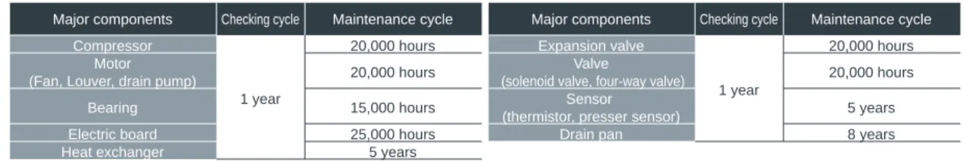
Maintenance cycle [Note that maintenance cycle does not mean guarantee period.]
Replacement cycle of consumable components
Note that replacement cycle does not mean guarantee period.]
YKB, YLM Series Lineup Catalogue
AIR CONDITIONING SYSTEMS
FM33568 / ISO 9001;2008