Before proceeding with the installation, please read carefully all the information in the manual as well as the procedures necessary for the correct installation and use of the unit. The warranty does not include payment for damage due to incorrect installation of the unit by the installer. The warranty does not include payment for damage resulting from improper use of the unit by the user.
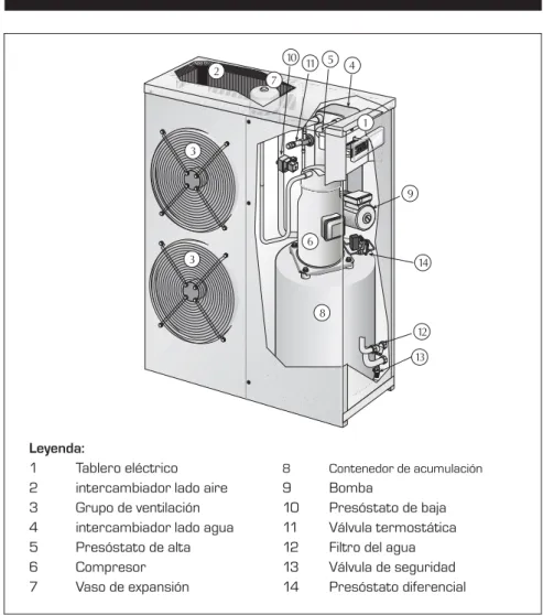
Located on the high pressure side of the refrigeration circuit, it shuts down the compressor operation in case of abnormal operating pressure. Located on the low pressure side of the refrigeration circuit, it shuts down the compressor operation in case of abnormal operating pressure. With the fixed calibration, located on the high pressure side of the refrigeration circuit, it shuts down the compressor operation in case of abnormal operating temperature.
It prevents freezing of the water in the evaporator during winter breaks. must be installed at the factory). It allows the reduction of the starting current that the machine must use during the start-up phase.
Technical cooling data (versions without accumulation)
Energy indices
Electrical data
Compressors
Fans
Sound data
Evaporator
Dimensions
Technical heating data (versions without accumulation)
Technical cooling data (versions with accumulation)
Technical heating data (versions with accumulation)
Figure 4 shows the correction coefficients if used with glycol water and correction coefficients to be used according to the degree of fouling of the exchanger. The maximum and minimum water flow rate limits are shown on the curves of the pressure drop diagrams. Please contact the AERMEC Technical Sales Office if it is necessary to operate the machine outside the limits indicated in the diagram.
If the machine is to be placed in a particularly windy position, wind breaks must be provided to avoid operating the DCPX in an unstable condition.
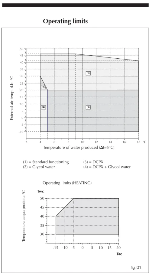
Operating limits
The resulting cooling capacity and the input electrical capacity at non-rated conditions are obtained by multiplying.
Cooling capacity and input power
Correction coefficient for H versions (cool functioning)
Heating capacity and input power
Correction coefficient for H versions (heating functioning)
Pressure drops
Evaporator pressure drops
Water filter pressure drops
Storage tank
Maximun water content of installation
Expansion tank calibration
Available static pressure for plant
Ethylene glycol solution
Correction factors for cooling capacity and power input take into account the presence of glycol. The water flow and pressure drop correction factor should be applied directly to the data obtained for glycol-free operation. The water flow correction factor is calculated to have the same ∆t as it would have without glycol.
The pressure loss correction factor already takes into account the deviating flow rate resulting from the application of the water flow correction factor. Based on fluid considered (water or air) one should enter the graph on the right or left side, from the intersection of the outdoor air temperature or process water lines and the relative curves, a point is obtained through which the vertical line passes showing both the percentage of glycol and the relative correction coefficients. To calculate the percentage of glycol based on the outside air temperature (figure 03A), enter from the left axis and after cutting the curve draw a vertical line which in turn will intersect all other curves. The points obtained from the upper curves represent the coefficients for the correction of the cooling power and input power for the flow rates and pressure drops (remember that these coefficients must be multiplied anyway by the nominal value of the size examined); while the bottom axis advises the percentage value of glycol needed based on the outdoor air temperature considered.
If you want to calculate the percentage of glycol on the basis of the treated water temperature (Figure 03A), you must enter from the right axis and when the curve is intersected draw a vertical line, which in turn intersects all the other curves; The points obtained from the upper curves will represent the coefficients of the cooling capacity and the input power of the flow rates and pressure drops (do not forget that these coefficients must be multiplied by the nominal value of the studied quantity anyway); while the lower axis indicates the percentage value of the glycol needed to produce water at the required temperature. It must be remembered that the initial quantities "Outdoor air temperature" and "Processed water temperature" are not directly connected to each other, therefore it will not be possible to enter the curve for one of these quantities and get the corresponding point on the other curve.
H versions
Check parameters
Protection device calibration
Fouling factors
Correction factors for ∆ t different from the rated value
Calibrations of control parameters and protection devices
ANZ AK 0507-0807-0907-1007-1507-2007
ANZ AK 0207-0257-0307-0417
Accessory compatibility table: (BKW)
Versions with electric heater
Electric absorption
B: for further information, refer to the documentation supplied with the unit, and if necessary contact the appropriate
Advanced control ANZ J - Control unit RE037A
Description of the control unit
- supplementary resistance LED Lit = ON / Unlit = OFF
Control logic for the compensation set
Heat compensation logic (fan coil)
ANZ 0307 H
ANZ 0417H
ANZ 050HA - 080HA
ANZ 0507H - 080H
ANZ 0907H
ANZ 0907HA
Size data
ANZ 050HAK - 050HAJ
ANZ 080HAK - 080HAJ
ANZ 0907HAK - 0907HAJ
ANZ 1007HAK - 1007HAJ
ANZ 150HAK - 150HAJ
ANZ 200HAK - 200HAJ
Índice Español
Contenido del manual
DECLARACIÓN DE CONFORMIDAD
Refrigerador aire - agua y bomba de calor serie ANZ resulta
Normas generales
Descripción y elección de la unidad
Versiones disponibles
Configurador
ATENCIóN: las versiónes K y J han sido diseñadas para la utilización de una resi- stencia elétrica de apoyo que no reemplaza las resistencias antihielo (provistas
Armazón y ventiladores
Componentes eléctricos
Regulación electrónica
Componenti idraulici
Componentes de seguridad y de control
Este accesorio asegura el correcto funcionamiento en refrigeración con temperaturas exteriores inferiores a 20°C a -10°C.Se compone de una tarjeta de control electrónico que varía el número de revoluciones de los ventiladores en función de la presión de condensación leída por el transductor de alta presión para mantenerla lo suficientemente alta como para alimentar correctamente la válvula termostática. La distancia máxima admisible de instalación es de 150 m con cable de 6 polos (modelo solo frío) o cable de 7 polos (bomba de calor) más pantalla con una sección mínima de 0,5 mm2. Permite realizar operaciones básicas de la máquina (encendido/apagado, cambio de modo de función, señalización de alarmas).
La distancia máxima admisible de instalación es de 30 m con cable de 6 polos (modelo sólo frío) o cable de 7 polos (bomba de calor) más pantalla de sección mínima 0,5 mm2. Resistencia eléctrica para el intercambiador de serpentín Evita la congelación del agua en el evaporador durante las paradas de invierno. Permite reducir la corriente de arranque requerida por la máquina en la fase de arranque.
ACCESORIOS
Datos técnicos enfriamiento (versiones sin acumulación)
Indices energéticos
Datos eléctricos
Compresores
Ventiladores
Evaporador
Dimensiones
Datos técnicos calentamiento (versiones sin acumulación)
Datos técnicos enfriamiento (versiones con acumulación)
Datos técnicos calentamiento (versiones con acumulación)
La figura 2 indica los coeficientes multiplicativos a aplicar a los datos nominales de potencia frigorífica disponible y potencia absorbida. La figura 4 indica los coeficientes de corrección, cuando se trabaja con agua glicolada y los coeficientes de corrección a utilizar en función del grado de suciedad del intercambiador. En la página 15 puede encontrar datos sobre la presión y el efecto de sonido de los dispositivos.
En su configuración estándar, los dispositivos no son adecuados para su instalación en un entorno salino. Los límites de caudal de agua máximo y mínimo están indicados por las curvas de los diagramas de caída de presión. En caso de que quiera utilizar la máquina fuera de los límites indicados en el esquema, póngase en contacto con el departamento técnico comercial de AERMEC.
En el caso de que la máquina esté ubicada en una zona con corrientes de aire, se recomienda instalar parabrisas para evitar un mal funcionamiento del dispositivo DCPX.
Límites de funcionamiento
La potencia frigorífica creada y la potencia absorbida en condiciones distintas a las nominales se obtienen multiplicando los valores nominales.
Coeficiente correctivo para las versiones H (funcionamiento en frío)
Coeficiente correctivo para las versiones H (funcionamiento en calor)
Pérdidas de cargado y preponderancias
Pérdida de carga evaporador
Pérdidas de carga filtro agua
Modelos con acumulación
Máximo contenido de agua de la instalación
Calibrado de la vadija de expansión
Prevalencia útil a la instalación
Soluciones de glicol etilénico
Los factores de corrección de potencia frigorífica y absorbida tienen en cuenta la presencia de glicol. Los factores de corrección para el flujo de agua y la caída de presión deben aplicarse directamente a los datos obtenidos para el funcionamiento sin glicol. El factor de corrección del caudal de agua se calcula para mantener el mismo Dt que sería en ausencia de glicol.
El factor de corrección de pérdida de carga ya tiene en cuenta el diferente caudal resultante de la aplicación del factor de corrección de caudal de agua. Según el fluido del que se trate (agua o aire), se debe acceder al gráfico desde el lado derecho o izquierdo, la intersección de las cuadrículas de temperatura exterior o temperatura del agua producida y las curvas correspondientes da el punto por el que debe pasar la línea vertical, que representa tanto el porcentaje de glicol como los coeficientes de corrección correspondientes. En caso de querer calcular el porcentaje de glicol de acuerdo a la temperatura del aire ambiente (Figura 03A), se deberá acceder por el eje izquierdo y cuando se cruce la curva, se dibujará una línea vertical para cruzar las demás curvas; Los puntos obtenidos de las curvas anteriores representan los coeficientes para la corrección de potencia frigorífica y absorbida por envíos y pérdidas de carga (recordar que estos coeficientes se deben multiplicar por el valor nominal del tamaño considerado);
Si desea calcular el porcentaje de glicol en función de la temperatura del agua producida (figura 03A), debe abrirlo por el eje derecho y una vez cortada la curva, se dibujará una línea vertical que a su vez cortará las demás curvas; Los puntos obtenidos de las curvas superiores representan los coeficientes de potencia frigorífica y absorbida, de los envíos y de las pérdidas de carga (recordar que estos coeficientes deben multiplicarse por el valor nominal del tamaño en cuestión); Tenga en cuenta que las medidas iniciales "Temperatura exterior" y "Temperatura del agua producida" no están directamente relacionadas, por lo que no es posible acceder a la curva de una de estas medidas y obtener el punto correspondiente en la otra curva.
Datos sonoros
Versiones H
Parámetros de control
Ajuste de los dispositivos de protección
Factores de incrustación
Factores correctivos para ∆ t distintos del nominal
Calibrados parámetros de control y dispositivos de protección
Versiones con resistencia eléctrica
Resistencia eléctrica BKW (Accessorios)
Consumos eléctricos
Control evolucionado ANZ J - Centralita RE037A El dispositivo de regulación RE037A
A : Reducción set point en calentamiento B : Pendiente
C : no utilizado D : no utilizado
Descripción de la centralita
F : no utilizado G : led cierre válvula
L : led funcionamiento normal M : led funcionamiento en modalidad
Lógica de control para el set de compensación
Lógica de compensación en calor (fan coil)
ANZ 0507 - 0807 Con acumulación y resistencia eléctrica
ANZ 0907 - 1007Con acumulación y resistencia eléctrica