GRUNDFOS DATA BOOKLET
ALPHA2/ALPHA3
Circulator pumps
50/60 Hz
Note: The test was commissioned and paid for by Grundfos Holding A/S.
Table of contents
ALPHA2/ALPHA3
1. General description 3
Type key 3
Model type 3
Performance range 4
2. Applications 5
Pumped liquids 6
ALPHAx, the best choice for heating systems 6
ALPHAx features 8
3. Construction 9
Sectional drawing 9
Material specification 9
Motor and control box 9
Unique air vent system 10
4. Installation and startup 11
Installation 11
Electrical data 11
Startup 11
Liquid temperature 11
System pressure 11
Inlet pressure 11
Setting the pump 11
5. Guide to performance curves 13
Curve conditions 14
6. Performance curves and technical data 15
ALPHAx 15-40 15
ALPHAx 15-50 (N) 16
ALPHAx 15-60 (N) 17
ALPHAx 15-80 (N) 18
ALPHAx 25-40 (N) 19
ALPHAx 25-40 A 20
ALPHAx 25-50 (N) 21
ALPHAx 25-60 (N) 22
ALPHAx 25-60 A 23
ALPHAx 25-80 (N) 24
ALPHAx 32-40 (N) 25
ALPHAx 32-50 (N) 26
ALPHAx 32-60 (N) 27
ALPHAx 32-80 (N) 28
7. Accessories 29
Unions and valve kits 29
Insulating kits 29
ALPHA plugs 29
ALPHAx for the German market 30
ALPHAx for the international market 33
ALPHAx for the UK market 38
ALPHAx for the Austrian and Swiss markets 39
8. Grundfos Product Center 43
General description
ALPHA2/ALPHA3 1
1. General description
Grundfos ALPHA2/ALPHA3, referred to as ALPHAx in the following, is a complete range of circulator pumps with the following features:
• AUTOADAPT function which is suitable for most installations.
• Integrated differential-pressure control enabling adjustment of pump performance to the actual system requirements.
• Automatic night setback, selectable.
• Manual summer mode.
• Dry-running protection.
• ALPHA Reader.
• High-torque start.
• Display showing the actual power consumption in watt or the actual flow in m3/h.
• Motor based on permanent-magnet rotor/compact-stator technology.
ALPHAx is energy-optimised and complies with the EuP Directive, Commission Regulation (EC) No 641/2009, which has been effective as from 1 January 2013.
For ALPHAx pumps, the energy efficiency index (EEI) is ≤ 0.20, categorised as best in class. See page 14.
Grundfos blueflux® technology represents the best from Grundfos within energy-efficient motors and frequency converters. Grundfos blueflux® meets or exceeds legislative requirements for standard electric motors, such as EuP IE3 grade. See page 14.
The installation of an ALPHAx pump will reduce the power consumption considerably, reduce noise from thermostatic radiator valves and similar fittings and improve the control of the system.
ALPHAx offers a host of advantages:
Type key
* Exception: UK version, size 15 = 1 1/2".
Model type
This data booklet covers all models. The model type is stated on the nameplate. See fig. 1.
Fig. 1 Model type on nameplate Energy savings Automatic control of the differential
pressure.
Flexibility Suitable for installation in existing systems.
Night setback Automatic night setback, selectable.
Manual summer mode Summer mode.
Dry-running protection Protection of the pump against dry running during start and normal operation.
ALPHA Reader Support for balancing radiators in a heating system.
High-torque start Improved startup under harsh conditions.
Comfort Low-noise operation.
Safety Built-in electrical and thermal protection of the pump.
User friendliness Simple setting and operation.
Alarms Alarms indicated in the display.
Warnings Warnings indicated in the display.
Example ALPHAx 25 - 40 180
Pump range Standard version L: Limited
Nominal diameter (DN) of suction and discharge ports [mm] (15 = 1"*, 25 = 1 1/2", 32 = 2") Maximum head [dm]
Cast-iron pump housing N: Stainless-steel pump housing A: Pump housing with air separator Port-to-port length [mm]
TM06 1716 2515
General description
ALPHA2/ALPHA3
1
The table below shows the ALPHAx models with built-in functions and features.
Performance range
Fig. 2 Performance range, ALPHAx
Functions/features Model B
2012
Model C 2014
Model D Aug. 2015
ALPHA3 model A Nov. 2015
AUTOADAPT ● ● ● ●
Proportional pressure ● ● ● ●
Constant pressure ● ● ● ●
Constant curve ● ● ● ●
Automatic night setback ● ● ● ●
Manual summer mode ● ● ●
Dry-running protection ● ●
ALPHA Reader ●
High-torque start ● ●
ALPHAx XX-40 ● ● ● ●
ALPHAx XX-50 ● ● ● ●
ALPHAx XX-60 ● ● ● ●
ALPHAx XX-80 ● ● ●
TM05 2548 2114
ALPHA2/
ALPHA3
(ALPHA2/ALPHA3 XX-80) (ALPHA2/ALPHA3 XX-60) (ALPHA2/ALPHA3 XX-50) (ALPHA2/ALPHA3 XX-40)
Applications
ALPHA2/ALPHA3 2
2. Applications
ALPHAx is designed for circulating liquids in heating systems. You can also use pumps with stainless-steel pump housing in domestic hot-water systems.
ALPHAx is suitable for the following systems:
• Systems with constant or variable flows where it is desirable to optimise the pump duty point.
• Systems with variable flow-pipe temperature.
• Systems where night setback is desired.
You can select the appropriate pump type for a heating system according to the following guidelines:
Note: The data are approximate values. Grundfos cannot be held responsible for wrong sizing of pumps in heating systems.
ALPHAx is especially suitable for the following:
• Installation in existing systems where the differential pressure of the pump is too high during periods of reduced flow demand.
• Installation in new systems for fully automatic adjustment of the performance to flow demands without the use of bypass valves or similar expensive components.
Examples of systems
Fig. 3 One-pipe heating system
Fig. 5 Underfloor heating system
Fig. 6 Domestic hot-water recirculation system Range Radiator system
(Δt 20 °C) Underfloor heating
(Δt 5 °C) Pump type
[m2] [m3/h] [m3/h] ALPHAx
80-120 0.4 1.5 XX-40
120-160 0.5 2.0 XX-50
160-200 0.6 2.5 XX-60
200-300 0.8 3.5 XX-80
TM05 2681 03129 0312 TM05 2680 0312TM05 2678 0312
Applications
ALPHA2/ALPHA3
2
Pumped liquids
The pump is suitable for the following liquids:
• clean, thin, non-aggressive and non-explosive liquids, not containing solid particles or fibres
• cooling liquids, not containing mineral oil
• softened water.
The kinematic viscosity of water is = 1 mm2/s (1 cSt) at 20 °C. If you use the pump for a liquid with a higher viscosity, the hydraulic performance of the pump will be reduced.
Example: 50 % glycol at 20 °C means a viscosity of approx. 10 mm2/s (10 cSt) and a reduction of pump performance by approx. 15 %.
Do not use additives that in any way can/will disturb the functionality of the pump.
When selecting a pump, take the viscosity of the pumped liquid into consideration.
ALPHAx, the best choice for heating systems
The heating required in a building varies greatly during the day due to changing outdoor temperatures, solar radiation and heat emanating from people, electric appliances, etc.
Add to this that the need for heating may vary from one section of the building to another and that the
thermostatic valves of some radiators may have been turned down by the users.
These circumstances will cause an uncontrolled pump to produce a too high differential pressure when the heat demand is low.
Possible consequences:
• too high energy consumption
• irregular control of the system
• noise in thermostatic radiator valves and similar fittings.
ALPHAx automatically controls the differential pressure by adjusting the pump performance to the actual heat demand, without the use of external components.
The pump has the following control modes:
• AUTOADAPT control
• proportional-pressure control
• constant-pressure control
• constant-curve control
• balancing control.
AUTO
ADAPTThe integrated AUTOADAPT function is especially developed for the following:
• underfloor heating systems
• two-pipe heating systems.
The AUTOADAPT function (factory setting)
automatically adjusts the pump performance to the actual heat demand, i.e. the size of the system and the changing heat demand. The performance is adjusted gradually over time. You cannot expect an optimum pump setting from day one.
If the power supply fails or is disconnected, the pump stores the AUTOADAPT setting in an internal memory and will resume the automatic adjustment when the power supply has been restored.
Operation
The AUTOADAPT function enables ALPHAx to control the pump performance automatically:
• adjustment of the pump performance to the heat demand in the system
• adjustment of the pump performance to the variations in load over 24 hours.
In AUTOADAPT mode, the pump is set to proportional-pressure control.
Fig. 7 AUTOADAPT performance range
The AUTOADAPT function differs from other control functions as it moves the control curve within a
performance range. The marked area indicates the limits for the movement of the proportional-pressure curve.
See fig. 7.
In a system with an uncontrolled pump, a pressure rise will often cause flow-generated noise in the
thermostatic radiator valves. This noise will be reduced considerably with ALPHAx.
TM03 9504 4107
H
Q Max. curve
Proportional-pressure curve Setpoint
Applications
ALPHA2/ALPHA3 2
Proportional-pressure control
Proportional-pressure control adjusts the pump performance to the actual heat demand in the system, but the pump performance follows the selected performance curve, PP1, PP2 or PP3. See fig. 8 where PP2 has been selected. See Change of performance for further information.
Fig. 8 Three proportional-pressure curves/settings
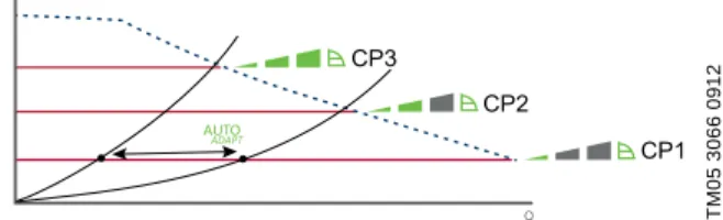
Constant-pressure control
Constant-pressure control adjusts the pump
performance to the actual heat demand in the system, but the pump performance follows the selected performance curve, CP1, CP2 or CP3. See fig. 9 where CP1 has been selected. See Change of performance for further information.
Fig. 9 Three constant-pressure curves/settings The selection of the right constant-pressure setting depends on the characteristics of the heating system in question and the actual heat demand.
Constant-curve control
At constant-curve/constant-speed operation, the pump runs at a constant speed, independent of the actual flow demand in the system. The pump performance follows the selected performance curve, I, II or III. See fig. 10 where II has been selected. See Change of performance for further information.
Fig. 10 Three constant-curve/constant-speed settings The selection of the right constant-curve/
constant-speed setting depends on the characteristics of the heating system in question and the number of taps likely to be opened at the same time.
Advantages of ALPHA pump control
In ALPHAx, control is effected by adapting the differential pressure to the flow (proportional-pressure and constant-pressure control).
Contrary to an uncontrolled pump, the
proportional-pressure-controlled ALPHAx reduces the differential pressure as a result of falling heat demand.
If the heat demand falls, for instance due to solar radiation, the thermostatic radiator valves will close, and, for the uncontrolled pump, the flow resistance of the system will rise, for instance from A1 to A2. See fig.
11.
In a heating system with an uncontrolled pump, this situation will cause a pressure rise in the system by ΔH1.
Fig. 11 Uncontrolled pump
In a system with an ALPHAx pump, the pressure will be reduced by ΔH2 and result in a reduced energy consumption. See fig. 12.
Fig. 12 Pump in proportional-pressure control mode
TM05 3064 0912TM05 3066 0912TM05 3068 0912
PP3
PP2 PP1
Q H
Q H
CP3
CP2
CP1
Q H
TM01 9119 5002TM01 9120 5002
H
Q
ΔH1
1 2
A2
A1
Q1
Q2
H
Q
ΔH2
A2 1
A1
A3
Q1
Q2
Applications
ALPHA2/ALPHA3
2
ALPHAx features
Automatic night setback
You enable the automatic night setback with the button on the control box.
Factory setting: Disabled.
Note: If you have set the pump to speed I, II or III, you cannot enable automatic night setback.
Once you have enabled automatic night setback, the pump automatically changes between normal duty and night setback. The changeover depends on the flow-pipe temperature measured by the integrated temperature sensor.
Function
If automatic night setback is to be used in the system, you must install the pump in the flow pipe.
Changeover between normal duty and night setback depends on the flow-pipe temperature.
The pump automatically changes over to night setback when a flow-pipe temperature drop of more than 10 to 15 °C within approx. two hours is registered. The temperature drop must be at least 0.1 °C/min.
Changeover to normal duty takes place without a time lag when the flow-pipe temperature has increased by approx. 10 °C.
Manual summer mode
You can select the manual summer mode from model C.
You enable the manual summer mode with the button on the control box.
Function
In the manual summer mode, the pump is
automatically started frequently at low speed to avoid blocking rotor as well as sticky valves and non-return valves. The display is turned off.
If any alarms occur during the manual summer mode, no alarms will be shown. When you deactivate the manual summer mode again, only the actual alarms will be displayed.
You deactive the manual summer mode by pressing any of the buttons, and then the pump returns to the previous mode and setting.
If you have enabled the automatic night setback mode before setting the manual summer mode, the pump will return to automatic night setback mode after the manual summer mode.
Dry-running protection
Dry-running protection is active from model D The new active dry-run feature protects the reliable wet-runner design of the ALPHAx pumps.
Dry-running protection protects the pump against dry running during start and normal operation. The user will be informed via an error code in the display.
ALPHA Reader
ALPHA Reader is selectable from ALPHA3
This feature is used for balancing radiators in a heating system in a fast and safe way for the benefit of the installer as well as the end-user.
ALPHA Reader provides read-out of internal data from the pump. See fig. 13. The data will be transmitted to a handheld device.
Fig. 13 ALPHA Reader
High-torque start
High-torque start is active from model D
In case of a blocked rotor, the pump will vibrate with the frequency of around 3 Hz during startup. Any dirt deposits that might prevent the impeller from rotating will be broken up swiftly and the pump will resume normal operation.
TM06 4452 2315
Construction
ALPHA2/ALPHA3 3
3. Construction
ALPHAx is designed for long and trouble-free
operation as a canned-rotor type, i.e. pump and motor form an integral unit without shaft seal and with only two gaskets for sealing. The bearings are lubricated by the pumped liquid. These constructions ensure maintenance-free operation.
The pump is characterised by the following:
• Permanent-magnet rotor/compact-stator motor which contribute to high efficiency and high starting torque.
• Ceramic shaft and radial bearings which contribute to long life.
• Carbon thrust bearing which contributes to long life.
• Stainless-steel rotor can, bearing plate and rotor cladding which contribute to corrosion-free long life.
• Composite impeller which contributes to corrosion-free long life.
• Cast-iron or stainless-steel pump housing which contributes to flexibility.
• Automatic air venting which contributes to easy commissioning.
• Compact design featuring pump head with integrated control box and control panel which fits into most common installations.
Sectional drawing
Fig. 14 Position numbers
Material specification
Motor and control box
The motor is a 4-pole synchronous permanent-magnet motor.
The pump controller is incorporated in the control box, which is fitted to the stator housing with two screws and connected to the stator via a terminal plug.
The control box has an integrated control panel with three push-buttons (pos. 1, 2 and 3) and a 2-digit 7-segment display. See fig. 15.
Fig. 15 Position of push-buttons
The display is on when you have switched on the power supply. The display shows the actual pump power consumption in watt (integer) or the actual flow in m3/h, in steps of 0.1 m3/h, during operation.
TM05 2518 0112
Pos. Description Material EN/DIN AISI/ASTM 1 Controller
complete Composite, PC
9 Rotor can Stainless steel 1.4401 316 Radial bearing Ceramics
11 Shaft Ceramics
Rotor cladding Stainless steel 1.4401 316 12
Thrust bearing Carbon Thrust bearing
retainer EPDM rubber
13 Bearing plate Stainless steel 1.4301 304 16 Impeller Composite, PES
18 Pump housing Cast iron EN-GJL-150 A48-150B Stainless steel 1.4308 351 CF8 Gaskets EPDM rubber
TM05 2519 0112
Pos. Description
1 Push-button for selection of pump setting.
2
Push-button for enabling or disabling of automatic night setback or manual summer mode. You have to activate both settings manually.
3
Push-button for selection of parameter to be shown in the display, i.e. actual power consumption in watt or actual flow in m3/h.
Construction
ALPHA2/ALPHA3
3
Faults preventing the pump from operating properly are indicated by fault codes in the display, for example blocked rotor.
The following faults can be indicated in the display:
• blocked rotor (E1)
• insufficient supply voltage (E2)
• electrical fault (E3).
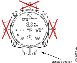
Figures 16 and 17 show the possible control box positions in heating systems as well as in air-conditioning and cold-water systems.
Fig. 16 Possible control box positions, heating systems
Fig. 17 Possible control box position, air-conditioning and cold-water systems
The plug incorporates cable relief and a locking function for securing the connection of the supply cable.
Fig. 18 ALPHA plug with cable relief and ALPHA plug, angled, with fixed cable
Unique air vent system
The pump housing with air separator is installed in systems where the liquid contains so much air that a circulator pump without air separator cannot start or keep up a continuous circulation. The pump housing is available only for upward water flows.
The air-containing liquid is guided from the suction port to the nozzle of the air-separating chamber and caused to circulate considerably in the relatively large chamber, thus creating a relatively lower pressure at the back (top) of the chamber. This lower pressure combined with the reduced velocity of the liquid in the air-separating chamber will cause a separation of air from the liquid. Due to its lower density, the air will escape through an automatic air vent fitted to the air-separating chamber.
The pump housing has an Rp 3/8 tapping for fitting of an air vent. The air vent is not supplied with the pump.
Fig. 19 Pump housing with air-separating chamber
Fig. 20 Air separation
TM05 2520 0112TM05 2700 0112TM05 3073 0612
Standard position
Standard position
1 2 3
TM05 2521 0112TM00 9101 1097
0 1 2 3 4 5 [%]
0 10 20 30 40 50 60 70 80 90 100 [%]
Luftudskillelse i %
Luftmængde i % af pumpemedie Q=0,5 m³/h
Q=1,0 m³/h Q=1,25 m³/h
Air separation as %
Quantity of air as % of pumped liquid Q = 0.5 m3/h
Q = 1.0 m3/h Q = 1.25 m3/h
Installation and startup
ALPHA2/ALPHA3 4
4. Installation and startup
Installation
In most cases, the installation of ALPHAx is reduced to the mechanical installation and connection to the power supply.
Always install the pump with horizontal motor shaft.
Fig. 21 Horizontal motor shaft
Electrical data
Startup
Do not start the pump until you have filled the system with liquid and vented it. Furthermore, the required minimum inlet pressure must be available at the pump inlet. You cannot vent the system cannot through the pump.
The pump is self-venting. Therefore, do not vent the pump before startup.
Liquid temperature
Cast-iron pumps: 2-110 °C.
In domestic hot-water systems, we recommend that you keep the liquid temperature between 45 and 65 °C to eliminate the risk of lime precipitation and legionella bacteria.
To avoid condensation in the control box and stator, the liquid temperature must always be higher than the ambient temperature. See table below.
The ALPHAx pump can, however, run at ambient temperatures higher than the liquid temperature if the plug connection in the pump head is pointing
downwards. See figs 16 and 17.
System pressure
PN 10: Maximum 1.0 MPa (10 bar).
Inlet pressure
To avoid cavitation noise and damage to the pump bearings, the following minimum pressures are required at the pump suction port.
Setting the pump
With the push-button on the control box, you can set the electronically controlled pump to the following:
• AUTOADAPT
• three proportional-pressure curves (PP1, PP2, PP3)
• three constant-pressure curves (CP1, CP2, CP3)
• three constant curves/constant speeds (I, II, III).
Factory setting
The push-buttons on the pump control box have been factory-set as shown in the table below.
These settings are suitable for a large majority of all single-family houses.
TM05 2522 0112
Supply voltage 1 x 230 V ± 10 %, 50/60 Hz, PE.
Motor protection The pump requires no external motor protection.
Enclosure class IPX4D.
Insulation class F.
Relative air humidity Maximum 95 %.
Ambient temperature 0-40 °C.
Temperature class TF110 to CEN 335-2-51.
EMC (electromagnetic compatibility)
2004/108/EC
Standards used: EN 55014-1:2006 and EN 55014-2:1997.
Sound pressure level ≤ 43 dB(A).
Ambient temperature [°C]
Liquid temperature Min.
[°C]
Max.
[°C]
0 2 110
10 10 110
20 20 110
30 30 110
35 35 90
40 40 70
Liquid temperature 75 °C 90 °C 110 °C
Inlet pressure
0.5 m head 2.8 m head 10.8 m head 0.005 MPa 0.028 MPa 0.108 MPa
0.05 bar 0.28 bar 1.08 bar
Pump type Setting Automatic night setback
Manual summer mode ALPHAx XX-40
ALPHAx XX-50 ALPHAx XX-60 ALPHAx XX-80
AUTOADAPT Disabled Disabled
Installation and startup
ALPHA2/ALPHA3
4
Change of performance
The pump performance (flow and head) can be changed by pressing the control box push-button as indicated in fig. 22 and the table below.
Fig. 22 Pump setting in relation to pump performance
TM05 2771 0412
II III I
H
PP3 CP3
CP2 PP1
CP1 PP2
Setting Pump curve Function
AUTOADAPT factory setting
Highest to lowest proportional-pressure curve
The AUTOADAPT function enables the pump to control the pump performance automatically within a defined performance range. See fig. 22.
• Adjustment of the pump performance to the size of the system.
• Adjustment of the pump performance to the variations in load over time.
In AUTOADAPT, the pump is set to proportional-pressure control.
PP1
Lowest
proportional-pressure curve
The duty point of the pump will move up or down on the lowest proportional-pressure curve, depending on the heat demand in the system. See fig. 22.
The head (pressure) is reduced at falling heat demand and increased at rising heat demand.
PP2
Intermediate proportional-pressure curve
The duty point of the pump will move up or down on the intermediate proportional-pressure curve, depending on the heat demand in the system. See fig. 22.
The head (pressure) is reduced at falling heat demand and increased at rising heat demand.
PP3
Highest
proportional-pressure curve
The duty point of the pump will move up or down on the highest proportional-pressure curve, depending on the heat demand in the system. See fig. 22.
The head (pressure) is reduced at falling heat demand and increased at rising heat demand.
CP1
Lowest
constant-pressure curve
The duty point of the pump will move out or in on the lowest constant-pressure curve, depending on the heat demand in the system. See fig. 22.
The head (pressure) is kept constant, irrespective of the heat demand.
CP2
Intermediate constant-pressure curve
The duty point of the pump will move out or in on the intermediate constant-pressure curve, depending on the heat demand in the system. See fig. 22.
The head (pressure) is kept constant, irrespective of the heat demand.
CP3
Highest constant-pressure curve
The duty point of the pump will move out or in on the highest constant-pressure curve, depending on the heat demand in the system. See fig. 22.
The head (pressure) is kept constant, irrespective of the heat demand.
III Speed III
The pump runs on a constant curve which means that it runs at a constant speed.
In speed III, the pump is set to run on the maximum curve under all operating conditions. See fig. 22.
You can obtain quick venting of the pump by setting the pump to speed III for a short period.
II Speed II The pump runs on a constant curve which means that it runs at a constant speed.
In speed II, the pump is set to run on the intermediate curve under all operating conditions. See fig. 22.
I Speed I The pump runs on a constant curve which means that it runs at a constant speed.
In speed I, the pump is set to run on the minimum curve under all operating conditions. See fig. 22.
Automatic night setback and manual summer mode
The pump changes to the curve for automatic night setback, i.e. absolute minimum performance and power consumption, provided that certain conditions are met. In manual summer mode, the pump is automatically started frequently at low speed to avoid a blocking rotor. The display is turned off.
See section ALPHAx features.
Guide to performance curves
ALPHA2/ALPHA3 5
5. Guide to performance curves
Each pump setting has its own performance curve (Q/H curve). However, AUTOADAPT covers a performance range.
A power curve (P1 curve) belongs to each Q/H curve. The power curve shows the pump power consumption (P1) in watt at a given Q/H curve.
The P1 value corresponds to the value that you cab read from the pump display. See fig. 23.
Fig. 23 Performance curves in relation to pump setting
TM05 2578 0312
II III I
Q P1
H
III II
I
PP3 CP3
CP2 PP1
CP1 PP2
Setting Pump curve
AUTOADAPT (factory setting) Setpoint within the marked area
PP1 Lowest proportional-pressure curve
PP2 Intermediate proportional-pressure curve
PP3 Highest proportional-pressure curve
CP1 Lowest constant-pressure curve
CP2 Intermediate constant-pressure curve
CP3 Highest constant-pressure curve
III Constant curve/constant speed III
II Constant curve/constant speed II
I Constant curve/constant speed I
Curve for automatic night setback/manual summer mode
Guide to performance curves
ALPHA2/ALPHA3
5
Curve conditions
The guidelines below apply to the performance curves on pages 15 to 27:
• Test liquid: airless water.
• The curves apply to a density of ρ = 983.2 kg/m3 and a liquid temperature of 60 °C.
• All curves show average values and should not be used as guarantee curves. If a specific minimum performance is required, make individual measurements.
• The curves for speeds I, II and III are marked.
• The curves apply to a kinematic viscosity of = 0.474 mm2/s (0.474 cSt).
• The conversion between head H [m] and pressure p [kPa] has been made for water with a density of ρ = 1000 kg/m3. For liquids with other densities, for example hot water, the discharge pressure is proportional to the density.
• Curves obtained according to EN 16297.
Symbols used on the following pages
Fig. 24 VDE comparison test energy efficiency index ALPHAx has been tested as the "Best in Test" by VDE in a comparison test on energy efficiency performed among six different pump manufacturers.
Note: The test was commissioned and paid for by Grundfos Holding A/S.
For ALPHAx pumps, the average energy efficiency index (EEI) is 0.15 categorised as best in class.
ALPHAx with AUTOADAPT function is the preferred choice for domestic installations and a true efficiency frontrunner.
The energy efficiency index (EEI) is the difference between the annual energy consumption of the ALPHAx and the standard consumption of a typical similar model.
The AUTOADAPT function ensures an energy
consumption that is even lower than the indicated EEI, but due to the calculation method, this is not reflected in the EEI.
The ALPHAx EEI is far below the EuP 2013 and 2015 requirements and even exceeds the best in class benchmark level. See fig. 25.
Fig. 25 EEI limits and the current positioning of the ALPHAx
With an energy efficiency index (EEI) well below the EuP benchmark level, you can achieve energy savings of up to 90 % compared to a typical circulator and thus a remarkably fast return on investment. This means, of course, that ALPHAx more than meets the standards of the EuP legislation.
For more information about the new energy directive, please visit:
TM05 2712 0412 TM05 4002 1912TM05 2683 0412
Index
10 0 20 30 40 50 80
60 90
70 100
EuP 2013
EuP
2015 Benchmark ALPHA2
EEI = 0.27 EEI = 0.23 EEI = 0.20 EEI = 0.15
energy.grundfos.com
Performance curves and technical data
6
6. Performance curves and technical data
ALPHAx 15-40
TM05 1672 4111- TM05 2712 0412 - TM05 2683 0312
Speed P1 [W] I1/1 [A] Connections: See Unions and valve kits, page 29.
AUTOADAPT 4-18 0.04 - 0.18 System pressure: Max. 1.0 MPa (10 bar).
Min. 3 0.04 Liquid temperature: 2-110 °C (TF 110).
Max. 18 0.18 Specific EEI: ≤ 0.15.
The pump incorporates overload protection.
TM05 2364 5011
Pump type Dimensions [mm] Weights [kg] Ship. vol.
[m3]
L1 B1 B2 B3 B4 H1 H2 H3 G Net Gross
0.0 0.2 0.4 0.6 0.8 1.0 1.2 1.4 1.6 1.8 2.0 2.2 2.4 Q [m³/h]
0 1 2 3 4 [m]H
II III I
0.0 0.2 0.4 0.6 0.8 1.0 1.2 1.4 1.6 1.8 2.0 2.2 2.4 Q [m³/h]
0 5 10 15 20 [W]
P1
II III
I
PP1 CP1 PP2
CP2 PP3
CP3
Note: The test was commissioned and paid for by Grundfos Holding A/S.
Performance curves and technical data
6
ALPHAx 15-50 (N)
* UK version: G 1 1/2.
See product numbers and QR codes in section Accessories.
TM05 1673 4111 - TM05 2713 0412 - TM05 2683 0312
Speed P1 [W] I1/1 [A] Connections: See Unions and valve kits, page 29.
AUTOADAPT 4-26 0.04 - 0.24 System pressure: Max. 1.0 MPa (10 bar).
Min. 3 0.04 Liquid temperature: 2-110 °C (TF 110).
Max. 26 0.24 Specific EEI: ≤ 0.16.
The pump incorporates overload protection.
TM05 2364 5011
Pump type
Dimensions [mm] Weights [kg] Ship. vol.
[m3]
L1 B1 B2 B3 B4 H1 H2 H3 G Net Gross
ALPHAx 15-50 130 60.5 60.5 44.5 44.5 35.8 103.5 52 G 1* 1.8 2.0 0.00364
ALPHAx 15-50 N 130 60.5 60.5 44.5 44.5 35.8 103.5 52 G 1* 1.8 2.0 0.00364
0.0 0.2 0.4 0.6 0.8 1.0 1.2 1.4 1.6 1.8 2.0 2.2 2.4 2.6 2.8 Q [m³/h]
0 1 2 3 4 5 [m]H
II III I
0.0 0.2 0.4 0.6 0.8 1.0 1.2 1.4 1.6 1.8 2.0 2.2 2.4 2.6 2.8 Q [m³/h]
0 5 10 15 20 25 [W]P1
III II
I
PP1 CP1 PP3
CP3 CP2 PP2
Performance curves and technical data
6
ALPHAx 15-60 (N)
* UK version: G 1 1/2.
TM05 1674 4111 - TM05 2714 0412- TM05 2683 0312
Speed P1 [W] I1/1 [A] Connections: See Unions and valve kits, page 29.
AUTOADAPT 4-34 0.04 - 0.32 System pressure: Max. 1.0 MPa (10 bar).
Min. 3 0.04 Liquid temperature: 2-110 °C (TF 110).
Max. 34 0.32 Also available with: Stainless-steel pump housing, type N.
The pump incorporates overload protection. Specific EEI: ≤ 0.17.
TM05 2364 5011
Pump type Dimensions [mm] Weights [kg] Ship. vol.
[m3]
L1 B1 B2 B3 B4 H1 H2 H3 G Net Gross
ALPHAx 15-60 130 60.5 60.5 44.5 44.5 35.8 103.5 52 G 1* 1.8 2.0 0.00364
ALPHAx 15-60 N 130 60.5 60.5 44.5 44.5 35.8 103.5 52 G 1* 1.8 2.0 0.00364
0.0 0.2 0.4 0.6 0.8 1.0 1.2 1.4 1.6 1.8 2.0 2.2 2.4 2.6 2.8 3.0 Q [m³/h]
0 1 2 3 4 5 6
II III I
0.0 0.2 0.4 0.6 0.8 1.0 1.2 1.4 1.6 1.8 2.0 2.2 2.4 2.6 2.8 3.0 Q [m³/h]
0 5 10 15 20 25 30 35[W]P1
III II
I [m]H
PP1 CP1 CP3
CP2 PP2 PP3
Note: The test was commissioned and paid for by Grundfos Holding A/S.
Performance curves and technical data
6
ALPHAx 15-80 (N)
* UK version: G 1 1/2.
See product numbers and QR codes in section Accessories.
TM06 1285 2114
Speed P1 [W] I1/1 [A] Connections: See Unions and valve kits, page 29.
AUTOADAPT 4-50 0.04 - 0.44 System pressure: Max. 1.0 MPa (10 bar).
Min. 3 0.04 Liquid temperature: 2-110 °C (TF 110).
Max. 50 0.44 Specific EEI: ≤ 0.18.
The pump incorporates overload protection.
TM05 2364 5011
Pump type Dimensions [mm] Weights [kg] Ship. vol.
[m3]
L1 B1 B2 B3 B4 H1 H2 H3 G Net Gross
ALPHAx 15-80 130 60.5 60.5 44.5 44.5 35.8 103.5 52 G 1* 1.8 2.0 0.00364
PP1 CP1 PP2
CP2 PP3
CP3
Performance curves and technical data
6
ALPHAx 25-40 (N)
TM05 1672 4111- TM05 2712 0412- TM05 2683 0312
Speed P1 [W] I1/1 [A] Connections: See Unions and valve kits, page 29.
AUTOADAPT 4-18 0.04 - 0.18 System pressure: Max. 1.0 MPa (10 bar).
Min. 3 0.04 Liquid temperature: 2-110 °C (TF 110).
Max. 18 0.18 Also available with: Stainless-steel pump housing, type N.
The pump incorporates overload protection. Specific EEI: ≤ 0.15.
TM05 2364 5011
Pump type
Dimensions [mm] Weights [kg] Ship. vol.
[m3]
L1 B1 B2 B3 B4 H1 H2 H3 G Net Gross
ALPHAx 25-40 130 60.5 60.5 44.5 44.5 35.8 103.5 52 G 1 1/2 1.8 2.0 0.00364
ALPHAx 25-40 N 130 60.5 60.5 44.5 44.5 36.8 103.5 52 G 1 1/2 1.8 2.0 0.00364
ALPHAx 25-40 180 60.5 60.5 44.5 44.5 35.9 103.5 52 G 1 1/2 1.8 2.0 0.00364
0.0 0.2 0.4 0.6 0.8 1.0 1.2 1.4 1.6 1.8 2.0 2.2 2.4 Q [m³/h]
0 1 2 3 4 [m]H
II III I
0.0 0.2 0.4 0.6 0.8 1.0 1.2 1.4 1.6 1.8 2.0 2.2 2.4 Q [m³/h]
0 5 10 15 20 [W]P1
II III
I
PP1 CP1 PP2
CP2 PP3
CP3
Note: The test was commissioned and paid for by Grundfos Holding A/S.
Performance curves and technical data
6
ALPHAx 25-40 A
See product numbers and QR codes in section Accessories.
TM05 2016 4211- TM05 2715 0412 - TM05 2683 0312
Speed P1 [W] I1/1 [A] Connections: See Unions and valve kits, page 29.
AUTOADAPT 4-18 0.04 - 0.18 System pressure: Max. 1.0 MPa (10 bar).
Min. 3 0.04 Liquid temperature: 2-110 °C (TF 110).
Max. 18 0.18 Specific EEI: ≤ 0.18.
The pump incorporates overload protection.
TM05 2574 0212
Pump type Dimensions [mm] Weights [kg] Ship. vol.
[m3]
L1 B1 B2 B3 B4 H1 H2 H3 G Net Gross
ALPHAx 25-40 A 180 63.5 98 32 63 50 124 81 G 1 1/2 2.8 3.0 0.00396
0.0 0.2 0.4 0.6 0.8 1.0 1.2 1.4 1.6 1.8 2.0 Q [m³/h]
0 1 2 3 4 [m]H
II III I
0.0 0.2 0.4 0.6 0.8 1.0 1.2 1.4 1.6 1.8 2.0 Q [m³/h]
0 5 10 15 20 [W]P1
IIIII
I
PP1 CP1 CP3
CP2 PP2 PP3
Performance curves and technical data
6
ALPHAx 25-50 (N)
TM05 1673 4111- TM05 2713 0412- TM05 2683 0312
Speed P1 [W] I1/1 [A] Connections: See Unions and valve kits, page 29.
AUTOADAPT 4-26 0.04 - 0.24 System pressure: Max. 1.0 MPa (10 bar).
Min. 3 0.04 Liquid temperature: 2-110 °C (TF 110).
Max. 26 0.24 Also available with: Stainless-steel pump housing, type N.
The pump incorporates overload protection. Specific EEI: ≤ 0.16.
TM05 2364 5011
Pump type Dimensions [mm] Weights [kg] Ship. vol.
[m3]
L1 B1 B2 B3 B4 H1 H2 H3 G Net Gross
ALPHAx 25-50 130 60.5 60.5 44.5 44.5 35.8 103.5 52 G 1 1/2 1.8 2.0 0.00364
ALPHAx 25-50 N 130 60.5 60.5 44.5 44.5 36.8 103.5 52 G 1 1/2 1.8 2.0 0.00364
ALPHAx 25-50 180 60.5 60.5 44.5 44.5 35.9 103.5 52 G 1 1/2 1.8 2.0 0.00364
0.0 0.2 0.4 0.6 0.8 1.0 1.2 1.4 1.6 1.8 2.0 2.2 2.4 2.6 2.8 Q [m³/h]
0 1 2 3 4 5 [m]H
II III I
0.0 0.2 0.4 0.6 0.8 1.0 1.2 1.4 1.6 1.8 2.0 2.2 2.4 2.6 2.8 Q [m³/h]
0 5 10 15 20 25 [W]P1
III II
I
PP1 CP1 PP3
CP3 CP2 PP2
Performance curves and technical data
6
ALPHAx 25-60 (N)
See product numbers and QR codes in section Accessories.
TM05 1674 4111 - TM05 2714 0412 - TM05 2683 0312
Speed P1 [W] I1/1 [A] Connections: See Unions and valve kits, page 29.
AUTOADAPT 4-34 0.04 - 0.32 System pressure: Max. 1.0 MPa (10 bar).
Min. 3 0.04 Liquid temperature: 2-110 °C (TF 110).
Max. 34 0.32 Also available with: Stainless-steel pump housing, type N.
The pump incorporates overload protection. Specific EEI: ≤ 0.17.
TM05 2364 5011
Pump type
Dimensions [mm] Weights [kg] Ship. vol.
[m3]
L1 B1 B2 B3 B4 H1 H2 H3 G Net Gross
ALPHAx 25-60 130 60.5 60.5 44.5 44.5 35.8 103.5 52 G 1 1/2 1.8 2.0 0.00364
ALPHAx 25-60 N 130 60.5 60.5 44.5 44.5 36.8 103.5 52 G 1 1/2 1.8 2.0 0.00364
ALPHAx 25-60 180 60.5 60.5 44.5 44.5 35.9 103.5 52 G 1 1/2 1.8 2.0 0.00364
ALPHAx 25-60 N 180 60.5 60.5 44.5 44.5 36.9 103.5 52 G 1 1/2 1.8 2.0 0.00364
0.0 0.2 0.4 0.6 0.8 1.0 1.2 1.4 1.6 1.8 2.0 2.2 2.4 2.6 2.8 3.0 Q [m³/h]
0 1 2 3 4 5 6
II III I
0.0 0.2 0.4 0.6 0.8 1.0 1.2 1.4 1.6 1.8 2.0 2.2 2.4 2.6 2.8 3.0 Q [m³/h]
0 5 10 15 20 25 30 35[W]P1
III II
I [m]H
PP1 CP1 CP3
CP2 PP2 PP3
Note: The test was commissioned and paid for by Grundfos Holding A/S.
Performance curves and technical data
6
ALPHAx 25-60 A
See product numbers and QR codes in section Accessories.
TM05 2017 4211- TM05 2682 0312- TM05 2683 0312
Speed P1 [W] I1/1 [A] Connections: See Unions and valve kits, page 29.
AUTOADAPT 4-34 0.04 - 0.32 System pressure: Max. 1.0 MPa (10 bar).
Min. 3 0.04 Liquid temperature: 2-110 °C (TF 110).
Max. 34 0.32 Specific EEI: ≤ 0.20.
The pump incorporates overload protection.
TM05 2574 0212
Pump type
Dimensions [mm] Weights [kg] Ship. vol.
[m3]
L1 B1 B2 B3 B4 H1 H2 H3 G Net Gross
ALPHAx 25-60 A 180 63.5 98 32 63 50 124 81 G 1 1/2 2.8 3.0 0.00396
1.0 0.8 0.6 0.4 0.2
0.0 2.4 2.6 2.8 Q [m³/h]
0.0 0.2 0.4 0.6 0.8 1.0 1.2 1.4 1.6 1.8 2.0 2.2 2.4 2.6 2.8 Q [m³/h]
0 1 2 3 4 5 6 [m]H
II III I
1.2 1.4 1.6 1.8 2.0 2.2 0
5 10 15 20 25 30 [W]35P1
III II
I
PP1 CP1 CP3
CP2 PP2 PP3