Our primary North American manufacturing facility for air handling units and inline fans for commercial and residential applications is located in Bouctouche. In addition to quiet units with demand control, Systemair can also supply fans and dampers for fire protection. Systemair's range of air handling units can meet all requirements for healthcare premises, regardless of whether these have to do with air cleanliness, noise level or demand management.
In variable air volume (VAV) systems, the supply of cool air increases as the cooling load increases and the supply of air decreases as the load decreases. The VAV unit controls the air supply volume through the inlet duct velocity pressure sensor to maintain the air flow, as the air conditioner load in the room changes, the thermostat signal will reset the VAV controller to change the supply air volume to suit the room requirements. At any given setting, the regulator will maintain the required air volume regardless of whether the static inlet pressure changes.
Variable air volume units allow the design to take full advantage of load shifting from lights, use, sun and equipment diversity, which typically leads to up to 40%.
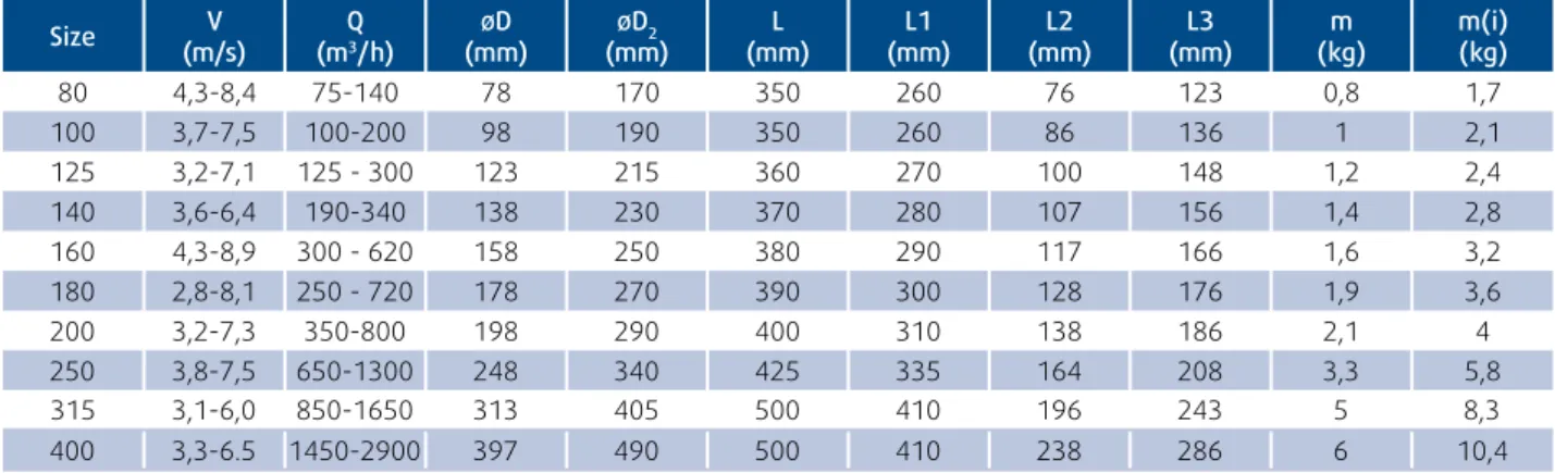
RPK-R
RPK-R-I
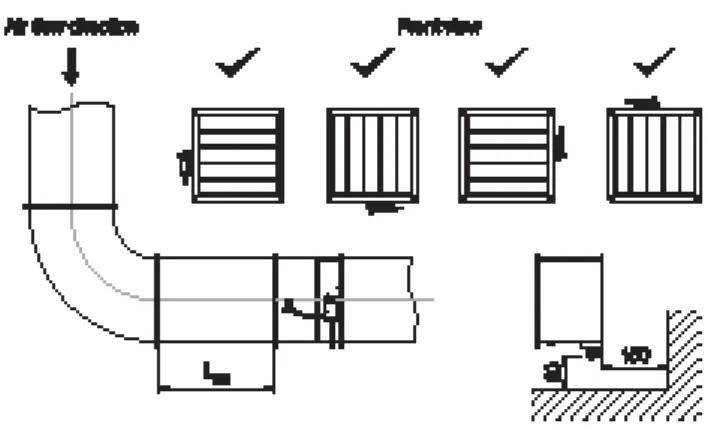
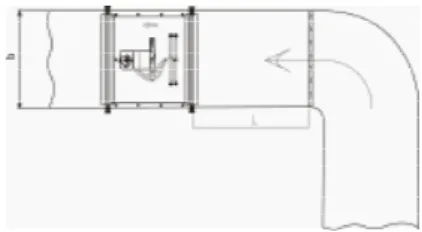
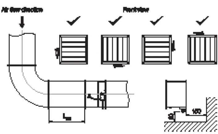
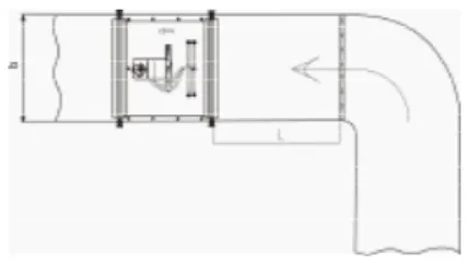
Pressure drop in duct system before RPK(1) ΔPZ1´´ …Pressure drop in duct system behind RPK(1) ΔPZ2´.
RPK-S
RPK-S-I
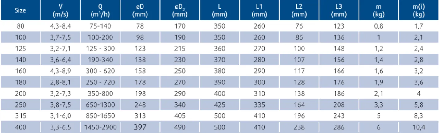
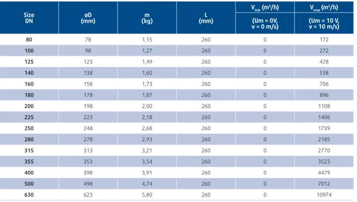
Optima terminal units are ideal for single-zone supply and return control in master and slave settings such as offices, hotel rooms or meeting rooms where the required cooling and heating load varies according to demand. The VAV terminal units are equipped as standard with BLC (Belimo compact) controllers (LMV-D3 or NMV-D3) without any MP or LON communication capability, which can be used independently or in a master and slave setup. VAV and Compact controllers are factory-calibrated to the air volume shown in the table as standard, but can be adjusted to the required on-site settings before shipment in the Vmin and Vmax range on request.
OPTIMA-R-25-353(m3/h)-2297(m3/h)-BLC4 The above order example is set for Vmin and Vmax air volume setting for Ø250 with Belimo compact controller which has NO communication capability. Terminal units are ideal for single zone control with supply and return in master and slave configuration such as offices, hotel rooms or meeting rooms where the required cooling and heating load will vary on demand. The VAV terminal units are standard equipped with BLC (Belimo compact) controllers (LMV-D3 or NMV-D3) without any MP or LON communication capability to be used as stand-alone or in master and slave environment.
OPTIMA-R-I-25-353(m3/h)-2297(m3/h)-BLC4 The example sequence above is set to set the air volume Vmin and Vmax for Ø250 with the Belimo compact controller that has NO overall capability.
OPTIMA-RM
The main function of Optima-RM is the maintenance of the overall parameters of air flow and pressure in the controlled zone - this means maintaining the desired ratio between the air flow on the air supply and on the air extraction of the zone. The zone air extraction flow value is controlled according to the flow value on the zone air supply. The signal from the flow measurement on the zone air supply is connected to the VAV controller on the zone extract as the desired air flow control value.
Thus, for the chosen flow rates, the identical values of the air flow rate on supply and exhaust are achieved (Tab.1). By adjusting the parameters of minimum and maximum air flow from the VAV controller to the exhaust air, it is possible to set the supply/exhaust ratio. Alternatively, gateway communication units can be supplied on request and can later be connected to building management systems to create zone control through bus-ring solutions (only possible if MP-Bus communication is installed).
The LDC effectively reduces the noise level at the outlet of the VAV unit or in the ductwork. Two silencers can be used together in series in installations where noise reduction is a particularly strong requirement, this can be very effective. For the most effective noise reduction, the silencer should be mounted immediately after the VAV connection unit and before the accessories such as Optima-R-MO (Round Multi-outlet units) or after the Accessories such as VBC (Water batteries).
For the most effective noise reduction, the silencer should be installed immediately downstream of the VAV terminal unit and before the accessory such as the Optima-RS-MO (Rectangular to Round Multi-Output Units) or after the accessory such as the VBR (Water). batteries). For the most effective noise reduction, the silencer should be installed immediately downstream of the VAV terminal unit and before the accessories such as the VBR (water batteries). The control units are pre-programmed, but can be configured for a specific application using the display and switches.
The standard color is white, but the frame and center can be delivered in several different colors upon request. The input can be connected to PT1000 type sensors and the sensor can be installed to sense the temperature on the supply pipe to the coil. In busy mode, the controller operates with a heating set point (22 °C) or a cooling set point (24 °C), which can be changed locally with low switches.
The set point can be adjusted up and down (±3°C) with the button on the front of the regulator. Switching between heating and cooling set points takes place automatically in the regulator depending on heating and cooling needs.
RC-CDO
28.8 V Differential pressure sensor
Connection cable The connection is made with the connection cable mounted on the VAV-Compact device. Settings and diagnostics The settings and diagnostics of the connected VAV-Compact controller can be easily and quickly checked and adjusted with the Belimo PC-Tool or with the ZTHGEN service tool. On-board service connection The service connection integrated in the VAV-Compact enables quick connection of the operating device used.
The operating and service equipment Belimo PC-Tool or the ZTH-GEN service tool can be inserted into the VAV-Compact (PP connection) or via the MP-Bus. Factory Settings The OEM VAV-Compact is installed in the VAV unit by the unit manufacturer, who adjusts and tests it according to the application. If desired, individual parameters can be adjusted for specific systems or services with a service tool (eg ZTH-GEN).
VAV – variable volumetric flow The VAV-Compact is supplied with the modulation setpoint by a room temperature controller via Modbus. The operating range (min and max) can be set either locally with PC-Tool or ZTH-GEN or via Modbus. Operating and service equipment Belimo PC-Tool or Service-Tool ZTH-GEN, connected to the VAV-Compact.
Mounting and connection The VAV-Compact device, which is mounted on the device by the OEM, is connected with the prefabricated connection cable. Registers < 100 (running) that can be written are volatile and must therefore be updated periodically. The fault bits can be reset with register 3 (command 4) or with the Belimo PC-Tool.
Setting and diagnostics The setting and the diagnostics of the connected VAV-Compact controller can be checked and set quickly and easily with the Belimo PC-Tool or the Service-Tool ZTH-GEN. On-board service connection The service connection integrated in the VAV-Compact allows the console in use to be connected quickly.
ZTH-GEN
Solution: Use the service connector on the actuator/VAV controller or temporarily disconnect the MP connection on the MP device from the MP bus and connect the ZTH-GEN to the MP connection. The control unit is started and the data of the connected device is read out when the ZTH-GEN is connected to the Belimo actuator/VAV controller. A quick start guide and a sticker with the basic functions for the back of the device are enclosed with the ZTH-GEN.
Volumetric flow and its transport are decisive factors for the energy consumption of fans. Control The energy requirements of the single room or DDC controller are transferred to the COU24-A-MP fan optimizer via analog signals or MP-Bus. Parallel control of supply and exhaust fans with the optimizer is not allowed.
The resulting actual volume flow signal from the master controller is the reference signal from the slave controller. When the supply and extract air VAV unit are connected in parallel, the reference signal is connected in parallel to the setpoint input of both VAV control circuits. The actual volume flow signal (OUT terminal - analog controller) is available as an analog signal independent of the optimiser's operating setting (setpoint input).
The resulting actual volumetric flow signal from the master controller is the reference signal for the slave controller. The actual volumetric flow signals of each connected VAV controller are available at the OUT terminals of the «Analog controller» optimizer connections. The actual volumetric flow signal from the VAV control is available from the optimizer (OUT terminal – analog controller).
When paralleling the supply and exhaust air VAV unit, the reference signal is connected in parallel to the two setpoint inputs of the supply and exhaust air optimizer. The resulting volumetric flow current signal of the main controller, tapped at the OUT terminal of.
MP BUS ®
Setpoint connection for an optimization system (continued) Setpoint connection of an MP master. DDC with MP interface or UK24LON/EIB) In an MP master system, the setpoints for the VAV controllers and the link between the supply and extract air systems are generated by the associated MP master (DDC or UK24LON/EIB). In a horizontal duct, the junction box should point upwards or be turned 90° to one side. I Connection for immersion sensor J Water in. operating pressure, at water temp. operating pressure, at water temp. in/out) Airflow Air.
DXRE
NOVA-R
NOVA-E
TUNE-R Damper
IGK IGC
NOVA-A NOVA-B
NOVA-L
TSO, TSOI Series