Product Manual KPMWC01102-11EN
Date: February 2011 Supersedes:
--
Water cooled chillers
WHB
SE (Standard Efficiency) 034.1 ÷ 159.2
Cooling Capacity from 120 to 570 kW
Refrigerant: R-134a
Index
Features and advantages ... 3
Features and advantages... 3
Seasonal quietness ... 3
Infinitely capacity control ... 3
Code requirements – Safety and observant of laws/directives ... 3
Certifications... 4
Versions ... 4
Sound configuration... 4
General characteristics ... 5
Cabinet and structure ... 5
Screw compressors ... 5
Ecological HFC 134a refrigerant ... 5
Evaporator ... 5
Condenser ... 5
Electronic expansion valve ... 5
Refrigerant Circuit... 5
Electrical control panel ... 6
Standard accessories (supplied on basic unit) ... 7
Nomenclature ... 9
Technical Specifications ... 10
WHB SE ST... 10
Sound levels ... 16
Sound pressure level correction for different distances ... 16
Operating limits... 17
How to use the Correction factors proposed in the previous tables... 18
Water charge, flow and quality ... 20
Water content in cooling circuits ... 21
Standard ratings... 22
WHB SE 034.1÷071.1ST... 22
WHB SE 080.1÷114.2ST... 24
WHB SE 128.2÷159.2 ... 26
Evaporator and condenser pressure drops... 28
WHB SE ST... 28
Dimensions... 29
WHB SE ST / 1 circuit ... 29
WHB SE ST / 2 circuits... 30
Installation notes... 31
Warning ... 31
Warning ... 31
Handling ... 31
Location... 31
Minimum space requirements ... 31
Technical specification for water cooled screw chillers... 32
General... 32
Refrigerant... 32
Performance ... 32
Unit description... 32
Noise level and vibration ... 32
Dimension ... 32
Chiller components... 33
ELWT fluctuation with steps capacity control (4 steps) EWLT fluctuation with stepless capacity control
Features and advantages
Features and advantages
The WHB SE ST water cooled chillers, featuring 1 or 2 single screw compressors, are manufactured to satisfy the requirements of the consultants and the end user. Units are designed to minimise energy costs while maximising the refrigeration capacities.
McQuay’s chiller design experience, combined with outstanding features makes the WHB SE ST chiller unmatched in the industry.
Seasonal quietness
The compressor design with a single screw and twin rotors allows a constant gas flow. This compression process completely eliminates gas pulsations. The oil injection also results in significant mechanical noise reduction.
The twin gas compressor discharge chambers are designed to act as attenuators, based on the harmonic wave principle with destructive interference, thus always resulting equal to zero. The extremely low noise compressor performance affords the use of WHB SE ST chiller for all applications.
The reduced number of vibrations produced from the WHB SE ST chiller offers a surprisingly quiet operation eliminating the noise transmission through the structure and the chilled water piping system.
Infinitely capacity control
Cooling capacity control is infinitely variable by means of a screw compressor controlled by microprocessor system.
Each unit has infinitely variable capacity control from 100%
down to 25% (one compressor unit) and down to 12,5% (two compressors units). This modulation allows the compressor capacity to exactly match the building cooling load without any leaving evaporator water temperature fluctuation. This chilled water temperature fluctuation is avoided only with a stepless control.
With a compressor load step control in fact, the compressor capacity, at partial loads, will be too high or too low compared to the building cooling load. The result is an increase in chiller energy costs, particularly at the part-load conditions at which the chiller operates most of the time.
Units with stepless regulation offer benefits that the units with step regulation are unable to match. The ability to follow the system energy demand at any time and the possibility to provide steady outlet water temperature without deviations from the set-point, are the two points that allow you to understand how the optimum operating conditions of a system can be met only through the use of a unit with step-less regulation.
Code requirements – Safety and observant of laws/directives
All water cooled units are designed and manufactured in accordance with applicable selections of the following:
Construction of pressure vessel 97/23/EC (PED)
Machinery Directive 2006/42/EC
Low Voltage 2006/95/EC
Electromagnetic Compatibility 2004/108/EC
tim e
Compressor Load
Building Load Building Load
Compressor Load
Certifications
All units manufactured are CE marked, complying with European directives in force, concerning manufacturing and safety.
On request units can be produced complying with laws in force in non European countries (ASME, GOST, etc.), and with other applications, such as naval (RINA, etc.).
Versions
WHB SE ST is available in standard efficiency version:
SE: Standard Efficiency
16 sizes, covering a cooling capacity range from 121 up to 571 kW, EER up to 4.41 and ESEER up to 5.37.
The EER (Energy Efficiency Ratio) is the ratio of the Cooling Capacity to the Power Input of the unit.
The Power Input includes: the power input for operation of the compressor, the power input of all control and safety devices.
The ESEER (European Seasonal Energy Efficiency Ratio) is a weighed formula enabling to take into account the variation of EER with the load rate and the variation of water inlet condenser temperature.
ESEER = A x EER100% + B x EER75% + C x EER50% + D x EER25%
A B C D
Coefficient 0.03 (3%) 0.33 (33%) 0.41 (41%) 0.23 (23%)
Condenser water inlet temperature (°C) 30 26 22 18
Sound configuration
WHB SE ST is available in standard sound level configuration:
ST: Standard Noise
General characteristics
Cabinet and structure
The cabinet is made of galvanized steel sheet and painted to provide a high resistance to corrosion. Colour Ivory White (Munsell code 5Y7.5/1) (±RAL7044).The base frame has eye-hook for lifting the unit with ropes for an easy installation. The weight is uniformly distributed along the profiles of the base and this facilitates the arrangement of the unit.
Screw compressors
The compressor is semi-hermetic, single-screw type with gate-rotors made of carbon impregnated engineered composite material. The compressor has one slide managed by the unit microprocessor for infinitely modulating the capacity between 100% to 25%. An integrated high efficiency oil separator maximizes the oil separation and standard start is Wye-delta (Y-Δ) type.
Ecological HFC 134a refrigerant
The compressors have been designed to operate with R-134a, ecological refrigerant with zero ODP (Ozone Depletion Potential) and very low GWP (Global Warming Potential) that means low TEWI (Total Equivalent Warming Impact).
Evaporator
The units are equipped with direct expansion plate to plate type evaporator, one per circuit. This heat exchanger is made of stainless steel brazed plates and is covered with a 10mm closed cell insulation material. The exchanger is equipped with an heater for protection against freezing down to –28°C.
The evaporator is manufactured in accordance to PED approval. The evaporator water outlet connections are provided with Victaulic Kit (as standard).
Condenser
The units are equipped with Direct Expansion shell & tube condenser, with copper tubes rolled into steel tube sheets. The unit has independent condensers, one per circuit. The condenser is manufactured in accordance to PED approval.
Condensers are provided with liquid shut-off valve and spring loaded relief valve.
The condenser water outlet connections are provided with Victaulic Kit (as standard).
Electronic expansion valve
The unit is equipped with the most advanced electronic expansion valves to achieve precise control of refrigerant mass flow.
As today’s system requires improved energy efficiency, tighter temperature control, wider range of operating conditions and incorporate features like remote monitoring and diagnostics, the application of electronic expansion valves becomes mandatory.
Electronic expansion valve proposes features that make it unique: short opening and closing time, high resolution, positive shut-off function to eliminate use of additional solenoid valve, highly linear flow capacity, continuous modulation of mass flow without stress in the refrigerant circuit and corrosion resistance stainless steel body.
Electronic expansion valve strength point is the capacity to work with lower ΔP between high and low pressure side, than a thermostatic expansion valve. The electronic expansion valve allows the system to work with low condenser pressure (winter time) without any refrigerant flow problems and with a perfect chilled water leaving temperature control.
Refrigerant Circuit
Each unit has independent refrigerant circuits and each one includes:
• Single screw compressor with integrated oil separator
• Brazed plate evaporator
• Shell & tube condenser
• Oil pressure transducer
• High pressure switches
Electrical control panel
Power and control are located in the main panel that is manufactured to ensure protection against all weather conditions.
The electrical panel is IP54 and (when opening the doors) internally protected with Plexiglas panel against possible accidental contact with electrical components (IP20). The main panel is fitted with a main switch interlocked door.
Power Section
The power section includes compressors fuses and control circuit transformer.
MicroTech III controller
MicroTech III controller is installed as standard; it can be used to modify unit set-points and check control parameters. A built-in display shows chiller operating status plus temperatures and pressures of water, refrigerant, programmable values, set-points. A sophisticated software with predictive logic, selects the most energy efficient combination of compressors and el ec t r o ni c e x p an s i on v a lv e t o k e ep s t a bl e o per a t in g c o n dit io ns t o m a x im is e c hi l ler e ne r g y ef f ic i e nc y and reliability.
MicroTech III is able to protect critical components based on external signs from its system (such as motor temperatures, refrigerant gas and oil pressures, correct phase sequence, pressure switches and evaporator). The input coming from the high pressure switch cuts all digital output from the controller in less than 50ms, this is an additional security for the equipment.
Fast program cycle (200ms) for a precise monitoring of the system. Floating point calculations supported for increased accuracy in P/T conversions.
Control section - main features
• Management of the compressor stepless capacity.
• Chiller enabled to work in partial failure condition.
• Full routine operation at condition of:
- high ambient temperature value - high thermal load
- high evaporator entering water temperature (start-up)
• Display of evaporator entering/leaving water temperatures.
• Display of condensing-evaporating temperatures and pressures, suction and discharge superheat for each circuit.
• Leaving water evaporator temperature regulation. Temperature tolerance = 0,1°C.
• Compressor and evaporator pumps hour counters.
• Display of Status Safety Devices.
• Number of starts and compressor working hours.
• Optimized management of compressor load.
• Re-start in case of power failure (automatic / manual).
• Soft Load (optimized management of the compressor load during the start-up).
• Start at high evaporator water temperature.
• Return Reset (Set Point Reset based on return water temperature).
• Set point Reset (optional).
• Application and system upgrade with commercial SD cards.
• Ethernet port for remote or local servicing using standard web browsers.
• Two different sets of default parameters could be stored for easy restore.
Safety
device / logic for each refrigerant circuit
• High pressure (pressure switch).
• High pressure (transducer).
• Low pressure (transducer).
• High compressor discharge temperature.
• High motor winding temperature.
• Phase Monitor.
• No pressure change at start.
System
security
• Phase monitor.
• Low Ambient temperature lock-out.
• Freeze protection.
Regulation
type
Proportional + integral + derivative regulation on the evaporator leaving water output probe.
MicroTech
III
MicroTech III built-in terminal has the following features.
• 164x44 dots liquid crystal display with white back lighting. Supports Unicode fonts for multi-lingual.
• Key-pad consisting of 3 keys.
• Push’n’Roll control for an increased usability.
• Memory to protect the data.
• General faults alarm relays.
• Password access to modify the setting.
• Application security to prevent application tampering or hardware usability with third party applications.
• Service report displaying all running hours and general conditions.
• Alarm history memory to allow an easy fault analysis.
Supervising systems (on request)
MicroTech III remote controlMicroTech III is able to communicate to BMS (Building Management System) based on the most common protocols as:
• ModbusRTU
• LonWorks, now also based on the international 8040 Standard Chiller Profile and LonMark Technology
• BacNet BTP certifief over IP and MS/TP (class 4) (Native) Chiller Sequencing
MicroTech III controller allows an easy plug-in sequencing technology based on digital or serial panel Digital Sequencing Panel
This panel is basically a step inserter that switches ON/OFF up to 11 units (chillers or heat pumps operating in the same cooling/heating mode) depending on the selected set point; the units are connected with the panel through standard cables and no serial card is requested.
Serial Sequencing Panel
Basically this panel sequences a chiller plant by switching on/off the units (up to 7 chillers) taking into account their running hours and the requested plant load, in order to optimise the number of working units for each condition; serial cards and shielded cables are requested to connect the panel with the units and, if installed, a BMS.
Standard accessories (supplied on basic unit)
Evaporator Victaulic Kit - Hydraulic joint with gasket for an easy and quick water connection.
20mm Evaporator Insulation Condenser Victaulic kit
Condenser Water side design pressure 16 bar Condenser 2 passes (Δt 4-8°C)
Suction line shut off valve - Suction shut-off valve installed on the suction of the compressor to facilitate maintenance
High Pressure Side Manometers
Y-D starter - Star Delta starter is the standard type
Double set-point - Dual leaving water temperature set-points.
Phase monitor - The phase monitor controls that phases sequence is correct and controls phase loss.
Evaporator flow switch for the water piping
Hour Run meter - Digital compressors hour run meter General fault contactor - Contactor for alarm warning.
Main switch interlock Emergency stop
Options (on request)
Heat pump versionBrine version – Allows the unit to operate down to -8°C leaving liquid temperature (antifreeze required).
Compressor thermal overload relays - Safety devices against compressor motor overloading in addition to the normal protection envisaged by the electrical windings.
Evaporator Water side design pressure 16 bar 20mm Condenser insulation
Condenser double flanges kit
Water pressure differential switch on evaporator Sound Proof System - Compressor sound enclosure.
Rubber type antivibration mounts – Supplied separately, these are positioned under the base of the unit during installation. Ideal to reduce the vibrations when the unit is floor mounted
Fork lift kit
Low pressure side manometers
Dual Pressure Relief Valve on evaporator
Under/Over Voltage – This device control the voltage value of power supply and stop the chiller if the value exceeds the allowed operating limits.
Energy Meter – This device allows to measure the energy absorbed by the chiller during its life. It is installed inside the control box mounted on a DIN rail and show on a digital display: Line-to-Line Voltage, Phase and Average Current, Active and Reactive Power, Active Energy, Frequency.
Condenser power factor correction - Installed on the electrical control panel to ensure it conforms to the plant rules (maximum 0,9).
Current limit display
Witness test – Every unit is always tested at the test bench prior to the shipment. On request, a second test can be carried out, at customer’s presence, in accordance with the procedures indicated on the test form. (Not available for units with glycol mixtures).
Acoustic test – On request, a test can be carried out, at customer’s presence (please contact the factory) (This test is not available for units with glycol mixtures).
Set-point reset, demand limit and alarm from external device – The leaving water temperature set-point can be overwritten with the following options: 4-20mA from external source (by user); outside ambient temperature; evaporator water temperature Δt. Moreover the device allow the user to limit the load of the unit by 4-20mA signal or by network system and the microprocessor is able to receive an alarm signal from an external device (pump etc… - user can decide if this alarm signal will stop or not the unit).
Automatic circuit breakers
Nomenclature
Machine type
WHB = Water Cooled chiller Model series
Letter A,B,…: major modification Efficiency level
SE = Standard Efficiency Unit size
034 ÷ 159.2 Always 3-digit code Number of compressors 1 ÷ 2
Sound configuration
ST = Standard Noise
WHB - SE 034 .1 ST
Technical Specifications
WHB SE ST
TECHNICAL SPECIFICATIONS 034.1 040.1 043.1 051.1
Capacity (1) kW 120 146 155 178
---
% 25 25 25 25
Unit power input (1) kW 27.3 33.3 38.5 44.2
--- 4.40 4.38 4.03 4.03
--- 5.01 4.67 4.67 4.66
Capacity (2) kW 142 172 188 216
Unit power input (2) kW 32.9 40.1 46.4 53.5
--- 4.32 4.29 4.05 4.04
--- ---
Height mm 1020 1020 1020 1020
Width mm 913 913 913 913
Length mm 2684 2684 2684 2684
kg 1177 1233 1334 1366
kg 1211 1276 1378 1415
---
l 14.3 18.1 14.4 16.7
Cooling l/s 5.73 6.98 7.41 8.50
Cooling kPa 15 13 40 38
--- No.
l 20.0 20.1 22.7 25.3
Cooling l/s 7.04 8.57 9.25 10.62
Cooling kPa 20 12 11 11
---
l 13 13 13 13
No. 1 1 1 1
Cooling dB(A) 71.4 71.4 71.4 71.4
Cooling dB(A) 88.6 88.6 88.6 88.6
---
kg. 18 20 33 34
No. 1 1 1 1
Piping connections mm 76.2 76.2 76.2 76.2
Piping connections inc. 21/2" 4" 4" 4"
Safety devices
Notes (1) Notes (2) Notes (3)
Compressor motor protection
Water freeze protection controller High oil filter pressure drop High discharge temperature
One per circuit
Low oil pressure
Low suction pressure (pressure transducer)
Emergency stop button
High discharge pressure (pressure switch)
Low pressure ratio
High discharge pressure (pressure transducer) Compressor
Dimensions Unit
Weight
Water heat exchanger Condenser
Unit
Operating Weight
Type
Quantity
R134a Semi-hermetic single screw compressor Double Pass Shell&Tube
Nominal Water pressure drop Water volume
Nominal water flow rate Number of condenser
Phase monitor
Evaporator water inlet/outlet Condenser water inlet/outlet
Insulation material Closed cell
Type Oil charge
Brased plate, one per circuit Water volume
Nominal water flow rate Type
Closed cell Nominal Water pressure drop
Refrigerant circuit
Sound level Sound Power (3)
Sound Pressure (3) Refrigerant type N. of circuits Refrigerant charge Water heat exchanger
Evaporator
Insulation material Cooling
Casing
Heating EER (1)
ESEER
Heating COP (2)
Version SE - ST Cooling
Capacity control Type Stepless
Minimum capacity
Ivory White
Galvanized and painted steel sheet Colour
Material
Cooling capacity, unit power input in cooling and EER are based on the following conditions: evaporator 12/7°C;
condenser 30/35°C, unit at full load operation.
The values are according to ISO 3744 and are referred to: evaporator 12/7°C, condenser 30/35°C, full load operation.
Heating capacity, unit power input in cooling and COP are based on the following conditions: evaporator 12/7°C; condenser 40/45°C, unit at full load operation.
TECHNICAL SPECIFICATIONS 057.1 071.1 080.1 085.2
Capacity (1) kW 208 256 285 310
---
% 25 25 25 12.5
Unit power input (1) kW 49.3 58.7 68.3 77.0
--- 4.22 4.37 4.18 4.03
--- 4.75 5.20 4.46 4.80
Capacity (2) kW 249 305 340 377
Unit power input (2) kW 59.6 71.7 80.8 92.9
--- 4.18 4.26 4.21 4.06
--- ---
Height mm 1020 1020 1020 2000
Width mm 913 913 913 913
Length mm 2684 2684 2684 2684
kg 1416 1600 1607 2668
kg 1473 1663 1675 2755
---
l 20.3 26.1 26.1 28.8
Cooling l/s 9.94 12.25 13.63 14.81
Cooling kPa 36 28 33 40
--- No.
l 28.7 28.7 32.0 45.4
Cooling l/s 12.30 15.06 16.89 18.49
Cooling kPa 11 16 26 11
---
l 13 16 16 26
No. 1 1 1 2
Cooling dB(A) 71.4 70.0 70.0 74.4
Cooling dB(A) 88.6 87.2 87.2 92.4
---
kg. 36 38 38 66
No. 1 1 1 2
Piping connections mm 76.2 76.2 76.2 76.2
Piping connections inc. 4" 4" 4" 4"
Safety devices
Notes (1) Notes (2) Notes (3)
Cooling capacity, unit power input in cooling and EER are based on the following conditions: evaporator 12/7°C;
condenser 30/35°C, unit at full load operation.
Water freeze protection controller
The values are according to ISO 3744 and are referred to: evaporator 12/7°C, condenser 30/35°C, full load operation.
Heating capacity, unit power input in cooling and COP are based on the following conditions: evaporator 12/7°C; condenser 40/45°C, unit at full load operation.
Phase monitor Emergency stop button Low oil pressure Low pressure ratio High oil filter pressure drop
R134a
High discharge pressure (pressure switch) Low suction pressure (pressure transducer) Condenser water inlet/outlet
High discharge pressure (pressure transducer) Evaporator water inlet/outlet
Nominal water flow rate
Insulation material Closed cell
Water volume Nominal water flow rate
Insulation material Closed cell
Nominal Water pressure drop
Type Brased plate, one per circuit
Operating Weight
Galvanized and painted steel sheet
Dimensions Unit
Ivory White
Capacity control Type Stepless
Minimum capacity
Refrigerant type Heating Heating EER (1)
Semi-hermetic single screw compressor Quantity
Version SE - ST Cooling
COP (2)
Compressor
Type
High discharge temperature Compressor motor protection N. of circuits
Refrigerant circuit Sound level
Refrigerant charge Cooling
Water volume Unit
ESEER
Water heat exchanger Evaporator
Material
Water heat exchanger Condenser
Type
Number of condenser
Casing Colour
Weight
Double Pass Shell&Tube
Sound Pressure (3) Sound Power (3)
One per circuit
Oil charge
Nominal Water pressure drop
TECHNICAL SPECIFICATIONS 094.2 102.2 108.2 114.2
Capacity (1) kW 334 357 386 416
---
% 12.5 12.5 12.5 12.5
Unit power input (1) kW 82.7 88.4 98.6 98.6
--- 4.04 4.04 3.91 4.22
--- 4.84 5.00 4.79 5.17
Capacity (2) kW 405 432 466 499
Unit power input (2) kW 99.9 107 113 119
--- 4.05 4.04 4.12 4.19
--- ---
Height mm 2000 2000 2000 2000
Width mm 913 913 913 913
Length mm 2684 2684 2684 2684
kg 2700 2732 2782 2832
kg 2792 2830 2888 2946
---
l 31.1 33.3 36.9 40.5
Cooling l/s 15.96 17.06 18.44 19.88
Cooling kPa 40 38 38 36
--- No.
l 48.0 50.6 54.0 57.3
Cooling l/s 19.91 21.28 23.15 24.59
Cooling kPa 11 11 11 11
---
l 26 26 26 26
No. 2 2 2 2
Cooling dB(A) 74.4 74.4 74.4 74.4
Cooling dB(A) 92.4 92.4 92.4 92.4
---
kg. 67 68 70 72
No. 2 2 2 2
Piping connections mm 76.2 76.2 76.2 76.2
Piping connections inc. 4" 4" 4" 4"
Safety devices
Notes (1) Notes (2) Notes (3) Weight
Type Water heat exchanger
Evaporator
Double Pass Shell&Tube Water heat exchanger
Condenser Nominal water flow rate Type
The values are according to ISO 3744 and are referred to: evaporator 12/7°C, condenser 30/35°C, full load operation.
Water freeze protection controller High discharge pressure (pressure switch)
High discharge temperature Low oil pressure
Low pressure ratio High oil filter pressure drop Phase monitor
Emergency stop button
Cooling capacity, unit power input in cooling and EER are based on the following conditions: evaporator 12/7°C;
condenser 30/35°C, unit at full load operation.
Heating capacity, unit power input in cooling and COP are based on the following conditions: evaporator 12/7°C; condenser 40/45°C, unit at full load operation.
Low suction pressure (pressure transducer) Compressor motor protection
High discharge pressure (pressure transducer)
R134a Refrigerant charge
Evaporator water inlet/outlet Sound Power (3)
Sound level
N. of circuits Refrigerant circuit
Refrigerant type
Condenser water inlet/outlet Compressor
Type
Sound Pressure (3) Quantity
Oil charge
Semi-hermetic single screw compressor Water volume
Nominal Water pressure drop Insulation material
Number of condenser One per circuit
Closed cell Nominal water flow rate
Nominal Water pressure drop Insulation material
Brased plate, one per circuit
Closed cell Water volume
Operating Weight Unit
Unit Colour Heating COP (2)
ESEER
Material
Ivory White
Galvanized and painted steel sheet Minimum capacity
EER (1)
Stepless Type
Cooling
Version SE - ST Cooling
Dimensions Capacity control
Casing
Heating
TECHNICAL SPECIFICATIONS 128.2 142.2 151.2 159.2
Capacity (1) kW 464 513 541 570
---
% 12.5 12.5 12.5 12.5
Unit power input (1) kW 108 117 127 137
--- 4.30 4.38 4.26 4.16
--- 5.27 5.37 5.25 4.81
Capacity (2) kW 554 610 645 681
Unit power input (2) kW 131 143 152 162
--- 4.22 4.26 4.23 4.22
--- ---
Height mm 2000 2000 2000 2000
Width mm 913 913 913 913
Length mm 2684 2684 2684 2684
kg 3016 3200 3207 3215
kg 3136 3327 3338 3350
---
l 46.4 52.2 52.2 52.2
Cooling l/s 22.17 24.51 25.85 27.23
Cooling kPa 36 28 28 33
--- No.
l 57.3 57.3 60.7 64.0
Cooling l/s 27.33 30.10 31.92 33.78
Cooling kPa 11 16 16 26
---
l 29 32 32 32
No. 2 2 2 2
Cooling dB(A) 73.8 73.0 73.0 73.0
Cooling dB(A) 91.8 91.0 91.0 91.0
---
kg. 74 76 76 76
No. 2 2 2 2
Piping connections mm 76.2 76.2 76.2 76.2
Piping connections inc. 4" 4" 4" 4"
Safety devices
Notes (1) Notes (2) Notes (3)
Stepless
Evaporator water inlet/outlet Nominal Water pressure drop
Insulation material Closed cell
Insulation material
The values are according to ISO 3744 and are referred to: evaporator 12/7°C, condenser 30/35°C, full load operation.
Heating capacity, unit power input in cooling and COP are based on the following conditions: evaporator 12/7°C; condenser 40/45°C, unit at full load operation.
Emergency stop button Low oil pressure
Version SE - ST
Condenser water inlet/outlet Sound Pressure (3) Oil charge
High discharge pressure (pressure switch) High discharge pressure (pressure transducer)
Water freeze protection controller Low pressure ratio
Phase monitor
Low suction pressure (pressure transducer) Compressor motor protection
Cooling capacity, unit power input in cooling and EER are based on the following conditions: evaporator 12/7°C;
condenser 30/35°C, unit at full load operation.
N. of circuits
R134a
High oil filter pressure drop High discharge temperature
Sound level Sound Power (3)
Refrigerant circuit
Refrigerant type Refrigerant charge Compressor
Type Semi-hermetic
single screw compressor Quantity
Water heat exchanger Condenser
Type Double Pass Shell&Tube
Water volume Nominal water flow rate Nominal Water pressure drop
Closed cell One per circuit Number of condenser
Water heat exchanger Evaporator
Type Brased plate, one per circuit
Nominal water flow rate Water volume
Weight Unit
Material
Dimensions Unit
Operating Weight
Galvanized and painted steel sheet COP (2)
EER (1)
Casing Colour Ivory White
Heating Heating ESEER
Cooling
Capacity control Type
Cooling
Minimum capacity
ELECTRICAL SPECIFICATIONS 034.1 040.1 043.1 051.1
--- 3 3 3 3
Hz 50 50 50 50
V 400 400 400 400
Minimum % -10% -10% -10% -10%
Maximum % +10% +10% +10% +10%
A 151 151 195 195
A 47 57 68 75
A 80 96 107 121
A 88 106 118 133
No. 3 3 3 3
V 400 400 400 400
Minimum % -10% -10% -10% -10%
Maximum % +10% +10% +10% +10%
A 80 96 107 121
---
ELECTRICAL SPECIFICATIONS 057.1 071.1 080.1 085.2
--- 3 3 3 3
Hz 50 50 50 50
V 400 400 400 400
Minimum % -10% -10% -10% -10%
Maximum % +10% +10% +10% +10%
A 195 288 288 281
A 85 99 113 135
A 145 161 182 214
A 160 177 200 235
No. 3 3 3 3
V 400 400 400 400
Minimum % -10% -10% -10% -10%
Maximum % +10% +10% +10% +10%
A 145 161 182 107+107
--- Voltage Tolerance
Maximum running current Voltage
Voltage Tolerance
Wye – Delta type (Y – Δ) Maximum running current
Maximum running current Unit
Voltage Tolerance Power Supply
Phase
Version SE - ST
Frequency
Nominal running current cooling Maximum starting current
Voltage
Wye – Delta type (Y – Δ) Maximum current for wires sizing
Starting method Phase
Unit
Maximum current for wires sizing Maximum starting current Nominal running current cooling
Starting method Voltage Compressor
Maximum running current
Version SE - ST
Compressor
Phase Power Supply
Phase Voltage Frequency
Voltage Tolerance
Maximum unit current for wires sizing is based on minimum allowed voltage Maximum current for wires sizing: (compressors full load ampere) x 1,1
Maximum running current is based on max compressor absorbed current in its envelope Notes
Allowed voltage tolerance ± 10%. Voltage unbalance between phases must be within ± 3%
Maximum starting current: starting current of biggest compressor + current of compressors at 75% maximum load Nominal current in cooling mode refers to the following conditions: evaporator 12°C/7°C; condenser 30/35°C
ELECTRICAL SPECIFICATIONS 094.2 102.2 108.2 114.2
--- 3 3 3 3
Hz 50 50 50 50
V 400 400 400 400
Minimum % -10% -10% -10% -10%
Maximum % +10% +10% +10% +10%
A 292 292 311 311
A 143 150 160 169
A 228 242 266 290
A 251 266 293 319
No. 3 3 3 3
V 400 400 400 400
Minimum % -10% -10% -10% -10%
Maximum % +10% +10% +10% +10%
A 107+121 121+121 121+145 145+145
---
ELECTRICAL SPECIFICATIONS 128.2 142.2 151.2 159.2
--- 3 3 3 3
Hz 50 50 50 50
V 400 400 400 400
Minimum % -10% -10% -10% -10%
Maximum % +10% +10% +10% +10%
A 404 417 434 434
A 183 197 212 226
A 306 322 343 364
A 337 354 377 400
No. 3 3 3 3
V 400 400 400 400
Minimum % -10% -10% -10% -10%
Maximum % +10% +10% +10% +10%
A 145+161 161+161 161+182 182+182
--- Wye – Delta type (Y – Δ) Compressor
Phase Voltage
Voltage Tolerance
Maximum running current Starting method Unit
Maximum starting current Nominal running current cooling Maximum running current Maximum current for wires sizing Voltage
Voltage Tolerance Frequency Voltage Tolerance Maximum starting current
Version SE - ST
Power Supply
Phase Frequency Voltage
Maximum running current Unit
Starting method Wye – Delta type (Y – Δ)
Maximum current for wires sizing Maximum running current
Power Supply
Phase
Nominal running current cooling
Compressor
Phase Voltage
Voltage Tolerance
Version SE - ST
Maximum unit current for wires sizing is based on minimum allowed voltage Maximum current for wires sizing: (compressors full load ampere) x 1,1
Maximum running current is based on max compressor absorbed current in its envelope Notes
Allowed voltage tolerance ± 10%. Voltage unbalance between phases must be within ± 3%
Maximum starting current: starting current of biggest compressor + current of compressors at 75% maximum load Nominal current in cooling mode refers to the following conditions: evaporator 12°C/7°C; condenser 30/35°C
Sound levels
WHB SE ST
Power 63 Hz 125 Hz 250 Hz 500 Hz 1000 Hz 2000 Hz 4000 Hz 8000 Hz dB(A) dB(A)
034.1 57.0 61.5 66.5 70.9 66.0 63.6 51.0 48.1 71.4 88.6
040.1 57.0 61.5 66.5 70.9 66.0 63.6 51.0 48.1 71.4 88.6
043.1 57.0 61.5 66.5 70.9 66.0 63.6 51.0 48.1 71.4 88.6
051.1 57.0 61.5 66.5 70.9 66.0 63.6 51.0 48.1 71.4 88.6
057.1 57.0 61.5 66.5 70.9 66.0 63.6 51.0 48.1 71.4 88.6
071.1 58.3 58.3 63.8 68.8 63.3 64.3 53.3 49.8 70.0 87.2
080.1 58.3 58.3 63.8 68.8 63.3 64.3 53.3 49.8 70.0 87.2
085.2 60.0 64.5 69.5 73.9 69.0 66.6 54.0 51.1 74.4 92.4
094.2 60.0 64.5 69.5 73.9 69.0 66.6 54.0 51.1 74.4 92.4
102.2 60.0 64.5 69.5 73.9 69.0 66.6 54.0 51.1 74.4 92.4
108.2 60.0 64.5 69.5 73.9 69.0 66.6 54.0 51.1 74.4 92.4
114.2 60.0 64.5 69.5 73.9 69.0 66.6 54.0 51.1 74.4 92.4
128.2 60.7 63.2 68.4 73.0 67.9 67.0 55.3 52.0 73.8 91.8
142.2 61.3 61.3 66.8 71.8 66.3 67.3 56.3 52.8 73.0 91.0
151.2 61.3 61.3 66.8 71.8 66.3 67.3 56.3 52.8 73.0 91.0
159.2 61.3 61.3 66.8 71.8 66.3 67.3 56.3 52.8 73.0 91.0
Unit size Sound pressure level at 1 m from the unit in semispheric free field (rif. 2 x 10⁻⁵ Pa)
(1) The values are according to ISO 3744 and are referred to: evaporator 12/7° C, condenser 30/35° C, full load operation.
(2) The above sound pressure levels will decrease by 4dB(A) when a compressor sound enclosure (option) is installed.
Sound pressure level correction for different distances
1m 5m 10m 15m 20m 25m
034.1 0.0 -7.9 -12.7 -15.8 -18.1 -19.8
040.1 0.0 -7.9 -12.7 -15.8 -18.1 -19.8
043.1 0.0 -7.9 -12.7 -15.8 -18.1 -19.8
051.1 0.0 -7.9 -12.7 -15.8 -18.1 -19.8
057.1 0.0 -7.9 -12.7 -15.8 -18.1 -19.8
071.1 0.0 -7.5 -12.2 -15.3 -17.5 -19.3
080.1 0.0 -7.9 -12.7 -15.8 -18.1 -19.8
085.2 0.0 -7.5 -12.2 -15.3 -17.5 -19.3
094.2 0.0 -7.5 -12.2 -15.3 -17.5 -19.3
102.2 0.0 -7.9 -12.7 -15.8 -18.1 -19.8
108.2 0.0 -7.5 -12.2 -15.3 -17.5 -19.3
114.2 0.0 -7.5 -12.2 -15.3 -17.5 -19.3
128.2 0.0 -7.5 -12.2 -15.3 -17.5 -19.3
142.2 0.0 -7.5 -12.2 -15.3 -17.5 -19.3
151.2 0.0 -7.5 -12.2 -15.3 -17.5 -19.3
159.2 0.0 -7.5 -12.2 -15.3 -17.5 -19.3
Unit size Distance
(1) The values are dB(A) (pressure level).
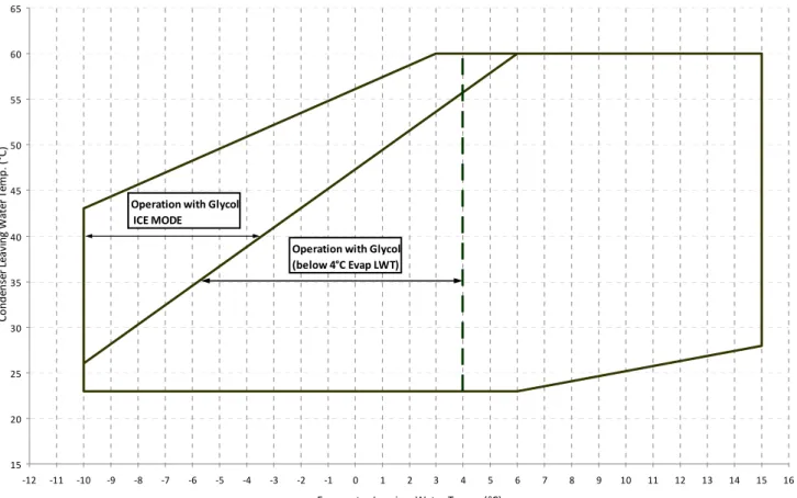
Operating limits
Table 1 - Evaporator/Condenser minimum and maximum water Δt
Max evaporator water Δt °C 8
Min evaporator water Δt °C 4
Min condenser water Δt °C 4
Max condenser water Δt °C 8
Table 2 - Evaporator fouling factors
Table 3 - Condenser fouling factors
Table 4.1 - Minimum glycol percentage for low water temperature
2 0 -2 -4 -6 -8
0.975
0.986 0.992
0.0880 0.957 0.974 0.983
0.962 0.978
1.000
0.1320 0.938
0.0176 1.000
EER correction factor
1.000
Evaporator Leaving Water Temperature (°C) Fouling factors
m2 °C / kW
Cooling capacity correction factor
0.0440
Power input correction factor 0.978
0.957 0.938
1.000 0.986 0.962 1.000
0.974
1.000 0.992 0.983 0.975 Fouling factors
m2 °C / kW
Cooling capacity correction factor
Power input correction factor
EER correction factor 0.0176
0.0440 0.0880 0.1320 15
20 25 30 35 40 45 50 55 60 65
‐12 ‐11 ‐10 ‐9 ‐8 ‐7 ‐6 ‐5 ‐4 ‐3 ‐2 ‐1 0 1 2 3 4 5 6 7 8 9 10 11 12 13 14 15 16
Evaporator Leaving Water Temp. (°C)
Condenser Leaving Water Temp. (°C)
Operation with Glycol ICE MODE
Operation with Glycol (below 4°C Evap LWT)
Table 4.2 - Minimum glycol percentage for low air temperature
-3 -8 -15 -23 -35
10% 20% 30% 40% 50%
-3 -7 -12 -20 -32
10% 20% 30% 40% 50%
Note (1): Minimum glycol percentage to prevent freezing of water circuit at indicated air ambient temperature
Table 5 - Correction factors for low evaporator leaving water temperature
2 0 -2 -4 -6 -8
0.842 0.785 0.725 0.670 0.613 0.562
0.950 0.940 0.920 0.890 0.870 0.840
Note: Correction factors have to be applied at working conditions: evaporator leaving water temperature 7°C
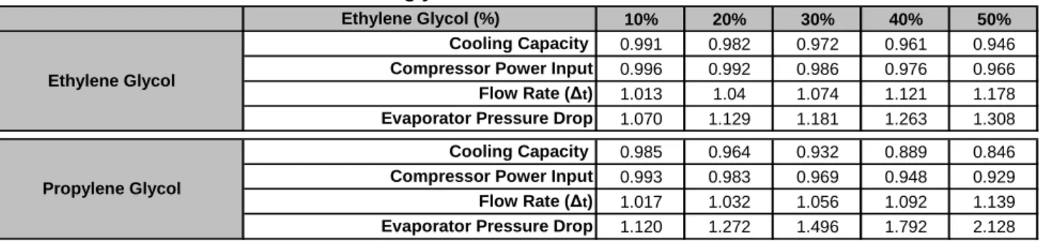
Table 6 - Correction factors for water and glycol mixture
10% 20% 30% 40% 50%
0.991 0.982 0.972 0.961 0.946
0.996 0.992 0.986 0.976 0.966
1.013 1.04 1.074 1.121 1.178
1.070 1.129 1.181 1.263 1.308
0.985 0.964 0.932 0.889 0.846
0.993 0.983 0.969 0.948 0.929
1.017 1.032 1.056 1.092 1.139
1.120 1.272 1.496 1.792 2.128
Air Ambient Temperature (°C) (2) Ethylene glycol (%) (1)
Compressor Power Input
Note (2): Air ambient temperature do exceed the operating limits of the unit, as protection of water circuit may be needed in winter season at non-working conditions
Propylene Glycol
Cooling Capacity Compressor Power Input Flow Rate (Δt) Evaporator Pressure Drop Flow Rate (Δt) Evaporator Pressure Drop Ethylene Glycol
Cooling Capacity Compressor Power Input Ethylene Glycol (%)
Evaporator Leaving Water Temperature (°C) Cooling Capacity
Propylene glycol (%) (1)
Air Ambient Temperature (°C) (2)
How to use the Correction factors proposed in the previous tables
A) Mixture Water and Glycol --- Evaporator leaving water temperature > 4°C
- depending from the type and percentage (%) of glycol filled in the circuit (see table 4.2 and 6) - multiply the Cooling Capacity, the Compressor Power Input by the Correction factor of Table 6
- starting from this new value of Cooling Capacity, calculate the Flow Rate (l/s) and the Evaporatore Pressure Drop (kPa) - now multiply the new Flow Rate and the new Evaporator Pressure Drop by the Correction Factors of Table 6
Example
Unit Size: WHB SE 034.1 ST
Mixture: Water
Working condition: ELWT 12/7°C – CLWT 30/35°C
- Cooling capacity: 121 kW
- Power input: 27.3 kW
- Flow rate (Δt 5°C): 5.78
- Evaporator pressure drop: 15kPa
Mixture: Water + Ethylene Glycol 30% (for a winter air temperature up to -15°C)
Working condition: ELWT 12/7°C – CLWT 30/35°C
- Cooling capacity: 121 x 0.972 = 118 kW
- Power input: 27.3 x 0.986 = 26.9 kW
- Flow rate (Δt 5°C): 5.64 (referred to 118 kW) x 1.074 = 6.06 l/s - Evaporator pressure drop: 16 (referred to 6.06 l/s) x 1.181 = 19kPa
B) Mixture Water and Glycol --- Evaporator leaving water temperature < 4°C
- depending from the type and percentage (%) of glycol filled in the circuit (see table 4.1 and 4.2 and table 6) - depending from the evaporator leaving water temperature (see table 5) - multiply the Cooling Capacity, the Compressor Power Input by the Correction factor of Table 5 and Table 6
- starting from this new value of Cooling Capacity, calculate the Flow Rate (l/s) and the Evaporatore Pressure Drop (kPa) - now multiply the new Flow Rate and the new Evaporator Pressure Drop by the Correction Factors of Table 6
Example
Unit Size: WHB SE 034.1 ST
Mixture: Water
Working condition: ELWT 12/7°C – CLWT 30/35°C
- Cooling capacity: 121 kW
- Power input: 27.3 kW
- Flow rate (Δt 5°C): 5.78
- Evaporator pressure drop: 15kPa
Mixture: Water + Glycol 30% (for a low evaporator leaving temperature of 0/-5°C)
Working condition: ELWT 0/-5°C – CLWT 30/35°C
- Cooling capacity: 121 x 0.641 x 0.972 = 75.4 kW
- Power input: 27.3 x 0.880 x 0.986 = 23.7 kW
- Flow rate (Δt 5°C): 3.60 l/s (referred to 75.4 kW) x 1.074 = 3.87 l/s
- Evaporator pressure drop: 7 kPa (referred to 3.87 l/s) x 1.181 = 9 kPa