R
R407C 407C
ENGLISH
INSTALLATION MANUAL
Air-cooled heat pumps with high-efficiency scroll compressor
he
Español
MANUAL DE INSTRUCCIONES
Bombas de calor condensadas por aire con compresor
scroll de alta eficacia
1 2
3
4 5
This manual contains :
Receipt of the product
Weights and
their distribution on the supports Minimum space requirements
Internal hydraulic circuit External hydraulic circuit recommended
Position and dimensions Plumbing connections
• Plumbing connections Electrical data
Electrical wiring Putting into service
Electrical data Electrical wiring Putting into service Use
Wiring diagrams MAINTENANCE
Receipt of the product 4 Position and fitting of the anti-vibration mountings 5 Plumbing section 7 Electrical wiring 10 Putting into service 11 Improper uses 12 Wiring diagrams 13
Dear Customer,
Thank you for choosing AERMEC. It is the fruit of many years of experience and special design studies and it has been made of the highest grade materials and with cutting edge technology.
In addition, all our products bear the CE mark indicating that they meet the requirements of the European Machine Directive regarding safety. The standard of quality is permanently being monitored and AERMEC products are therefore a synonym for Safety, Quality and Reliability.
If you do not know where our nearest After Sales Service is, you can get this from the dealership where the device was pur-
ENGLISH
TABLE OF CONTENTS
HE S1
S2 S4
Mod. Minimum technical spaces
mm S1 S2 S3 S4
020 150 500 150 500
025 250 500 250 500
030 250 500 250 500
040 300 500 300 500
050 300 500 300 500
080 300 500 300 500
090 300 500 300 500
100 750 300 750 1400 150 750 300 750 1400 200 750 300 750 1400
!
! MAX
Receipt of the product
Positioning
The machines in the HE series must be installed externally in an area that is suitable for the purpose that has the re- quired technical spaces. This is essential both to allow interventions of ordinary and extraordinary maintenance and for operating requirements For the proper functioning of the unit it must be instal- led on a perfectly fl at surface. Make sure that the resting surface is able to bear the weight of the machine. The device is made of galvanised steel sheet and hot painted with polyester powders to resist bad weather. This means that no particular measures have to be taken to protect the unit. If the machine is to be placed in a particularly windy position, wind breaks must be provided to avoid the DCPX operating in an unstable con- dition.
repair operations are possible. The war- ranty of the device does not in any case cover costs incurred as a result of mo- torised ladders, scaffolding or any other
HANDLING
Before moving the unit, examine the sizes, weights, centre of gravi- ty and lifting points, then check that the equipment for lifting and posi- tioning are suitable and comply with safety regulations currently in force.
Particular attention must be paid to all the loading, unloading and lifting opera- tions so as to avoid hazardous situations for people and damage to the structure and operational parts of the machine.
Under no circumstances may objects be placed on top of the unit. Personnel engaged in handling the machine must have the proper personal protection devices. Under no circumstance must anybody or anything stop under the unit even briefl y. During lifting you are advi- sed to fi t anti-vibration mountings and fi x them to the relative holes on the base unit in accordance with the moun- ting schematic supplied with the acces- sories (VT).
lifting systems made necessary to carry out the operations under warranty.
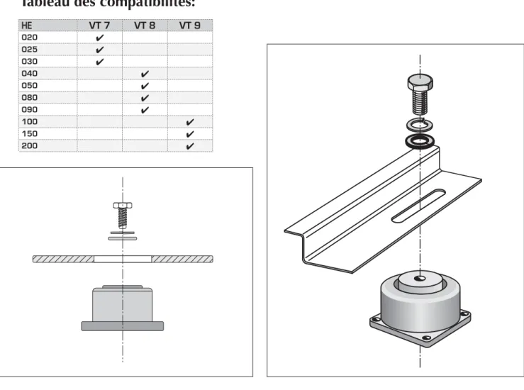
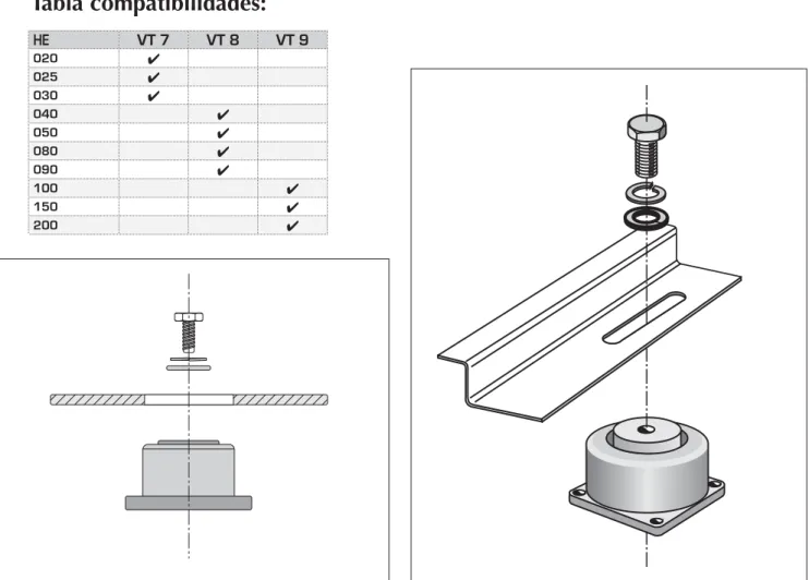
HE VT 7 VT 8 VT 9
020
025
030
040
050
080
090
100
150
200
Tableau des compatibilités:
Position and fitting of the anti-vibration mountings
Anti-vibration mountings can be com- bined with the unit (available as an accessory), thanks to which the vibra- tions produced by the compressor du- ring its functioning are dampened; the following diagrams show how to install
Fitting of the anti-vibration mountings:
these accessories on the unit depending on the model of the unit purchased.Eve- ry kit includes four anti-vibration moun- tings with the nuts and bolts necessary for fi tting them; remember to pay parti- cular attention to the positioning of the
unit during the fi tting of the anti-vibra- tion mountings, furthermore remember that the surface the unit is rested on must be perfectly level and able to support the weight of the unit.
C
A
Bx
By
D
B
Barycentre and position of the anti-vibration mountings:
C
B
Bx
By
D
A
Small base (P)
Grand socle (G)
Version HE H (with accumulation empty)
ANZ Socle Bx (mm) By (mm) A (mm) B (mm) C (mm) D (mm)
020 P 408 435 660 1120
025 P 408 435 660 1120
030 P 408 435 660 1120
040 P 408 435 660 1120
050 P 408 435 660 1120
080 P 408 435 660 1120
090 G 510 555 1072 1167
100 G 707 750 1670 1750
150 G 707 750 1670 1750
200 G 707 750 1670 1750
Version HE H (with accumulation full of water)
ANZ Basamento Bx (mm) By (mm) A (mm) B (mm) C (mm) D (mm)
020 P 408 435 660 1120
025 P 408 435 660 1120
030 P 408 435 660 1120
040 P 408 435 660 1120
050 G 408 435 660 1120
080 G 408 435 660 1120
090 G 510 555 1072 1167
100 G 707 750 1670 1750
150 G 707 750 1670 1750
200 G 707 750 1670 1750
Version HE (with accumulation full of water)
ANZ Basamento Bx (mm) By (mm) A (mm) B (mm) C (mm) D (mm)
020 P 408 435 660 1120
025 P 408 435 660 1120
030 P 408 435 660 1120
040 P 408 435 660 1120
050 G 408 435 660 1120
Version HE (with accumulation empty)
ANZ Basamento Bx (mm) By (mm) A (mm) B (mm) C (mm) D (mm)
020 P 408 435 660 1120
025 P 408 435 660 1120
030 P 408 435 660 1120
040 P 408 435 660 1120
050 G 408 435 660 1120
080 G 408 435 660 1120
090 G 510 555 1072 1167
100 G 707 750 1670 1750
150 G 707 750 1670 1750
200 G 707 750 1670 1750
Plumbing section
hydraulic circuit inside the unit
N.B.
For the correct design of the hydraulic sy- stem comply with local safety regulations currently in force. The following informa- tion constitutes suggestions for the cor- rect installation of the unit.
Standard equipment
The unit comes as standard with In the versions (U):
Plate-type heat exchanger
Differential pressure switch between the inlet and outlet of the evaporator to avoid problems of freezing if there is no fl ow of water.
For the sizes 020 - 025 - 030 - 040 - 050, the differential pressure switch is replaced by a fl ow switch.
Diaphragm type expansion tank with precharge of nitrogen.
The storage tank lowers the number of compressor peaks and standardise the temperature of the water to send to the users.
Circulation pump
In the versions (B):
Plate-type heat exchanger
Differential pressure switch between the inlet and outlet of the evaporator to avoid problems of freezing if there is no fl ow of water.
For the sizes 020 - 025 - 030 - 040 - 050, the differential pressure switch is replaced by a fl ow switch.
Diaphragm type expansion tank with precharge of nitrogen.
The storage tank lowers the number of compressor peaks and standardise the temperature of the water to send to the users.
Circulation pump
The fi gure shows some diagrams of the recommended hydraulic circuit between the HE chiller and the users.
In the case the following are not sup- plied with the unit, you are advised to install:
-Manual cut-off valves
Recommended hydraulic circuit
- Inertia storage tank - Charging assembly
- Flexible high-pressure joints - Expansion tank
- Safety valve - Drain valve N.B.
The hydraulic piping for connection to the machine must be properly scaled for the actual water fl ow rate required by the plant in the functioning.
The installer is responsible for the hydraulic parallel.
The water fl ow rate to the heat exchan- ger must always be constant.
CN
CN EV
1
3 2
4
5
6 7 8
9
11 12
14
10
13
10
11 13
14
HE U (singolo anello)
impianto a singolo circuito
ATTENZIONE:
• L’acquisto ed il montaggio di tutti i componenti esterni all’unità sono a carico dell’utente;
• Le valvole di intercettazione manuale tra l’unità ed il resto dell’impianto sono da considerarsi come componente consigliato;
• Si raccomanda un periodico controllo e/o manuten- zione del filtro acqua montato sulle unità;
!
LEGENDA:
Scambiatore lato aria Scambiatore lato acqua Valvola termostatica Compressore ZH Pompa di circolazione Vaso d’espansione Filtro acqua Serbatoio d’accumulo Valvola di sicurezza Rubinetti Collettore
Valvola unidirezionale Valvola solenoide Pannelli radianti 1
2 3 4 5 6 7 8 9 10 11 12 13 14
CN
CN EV
1
3 2
4
5
6 7 8
9
11 12
14
10 13
14
5 5
10
11 13
CN
CN EV
1
3 2
5 8
9
11 12
13 14
10 5
11 13
14
HE U (singolo anello)
impianto a doppio circuito
HE B (doppio anello)
ATTENZIONE:
• L’acquisto ed il montaggio di tutti i componenti esterni all’unità sono a carico dell’utente;
• Le valvole di intercettazione manuale tra l’unità ed il resto dell’impianto sono da considerarsi come componente consigliato;
• Si raccomanda un periodico controllo e/o manu- tenzione del filtro acqua montato sulle unità;
!
LEGENDA:
Scambiatore lato aria Scambiatore lato acqua Valvola termostatica Compressore ZH Pompa di circolazione Vaso d’espansione Filtro acqua Serbatoio d’accumulo Valvola di sicurezza Rubinetti Collettore 1
2 3 4 5 6 7 8 9 10 11
LEGENDA:
Scambiatore lato aria Scambiatore lato acqua Valvola termostatica Compressore ZH Pompa di circolazione Vaso d’espansione Filtro acqua Serbatoio d’accumulo Valvola di sicurezza Rubinetti Collettore
Valvola unidirezionale Valvola tre vie Pannelli radianti 1
2 3 4 5 6 7 8 9 10 11 12 13 14
Plumbing connection positions
A
E D
FGH
A5 A2 A3A4
B C
A1
HE 020 - 025 - 030 - 040 - 050
Version (U)
HE U In Out A (mm) B (mm) C (mm) D (mm) E (mm) F (mm) G (mm) H (mm)
020 A5 A4 430 230 70 108 188 235 285 325
025 A5 A4 430 230 70 108 188 235 285 325 030 A5 A4 430 230 70 108 188 235 285 325 040 A5 A4 430 230 70 108 188 235 285 325
050 A5 A4 430 230 70 108 188 235 285 325
HE 100 - 150 - 200
A
A1
Version (B)
HE B In Out A (mm) B (mm) C (mm) D (mm) E (mm) F (mm) G (mm) H (mm)
020 A1 A4 430 230 70 108 188 235 285 325
025 A1 A4 430 230 70 108 188 235 285 325 030 A1 A4 430 230 70 108 188 235 285 325 040 A1 A4 430 230 70 108 188 235 285 325
050 A1 A4 430 230 70 108 188 235 285 325
Version (U)
HE U In Out A (mm) B (mm) C (mm) D (mm) E (mm) F (mm)
080 A1 A5 46 210 280 340 388 440
090 A1 A5 46 210 280 340 388 440
Version (B)
HE B In Out A (mm) B (mm) C (mm) D (mm) E (mm) F (mm)
080 A4 A5 46 210 280 340 388 440 090 A4 A5 46 210 280 340 388 440
Version (U)
HE U In Out A (mm) B (mm) C (mm) D (mm) E (mm)
100 A1 A2 57 100 160 300 415
150 A1 A2 57 100 160 300 415 200 A1 A2 57 100 160 300 415
Version (B)
HE B In Out A (mm) B (mm) C (mm) D (mm) E (mm)
100 A1 A2 57 100 160 300 415
150 A1 A2 57 100 160 300 415 200 A1 A2 57 100 160 300 415
A
A1
HE 080 - 090
factory and to start it up it is neces- sary to have a power supply that works according to the indications on the rating plate of the unit, with cut off with protective devices on the line.
The cable cross sections and the scaling of the line main switch are purely indi- cative.
It will be up to the installation engineer to properly dimension the power line depending on the length, type of cable, unit consumption and physical position.
020 025 030 040 050
SEZ A mm2 2,5 2,5 4 4 6
SEZ B mm2 1 1 1 1 1
Terra mm2 2,5 2,5 4 4 6
IL A 13 16 20 20 25
All the electrical wirings must comply with the regulations in force at the time of the installation.
The diagrams and schematics in this documentation must only be used as an aid for the setting up of the electrical lines. Refer to the wiring diagram sup- plied with the device, for installation requirements.
N.B.
Check that all power cables are cor- rectly secured to the terminals when
switched on for the first time and after 30 days of use. Afterwards, check the connection of the power cables every six months. Slack terminals could cause the cables and components to ove- rheat.
Cross sections recommended for the maximum length of 50 m. The cross section of the cable and the dimension of the line main switch are purely indi- cative.
020 025 030 040 050 080 090 100 150 200
SEZ A mm2 1,5 1,5 2,5 2,5 2,5 2,5 4 4 6 10
SEZ B mm2 1 1 1 1 1 1 1 1 1 1
Terra mm2 1,5 1,5 2,5 2,5 2,5 2,5 4 4 6 10
IL A 8 8 10 10 13 13 16 20 25 32
HE U - HE B (230V single phase)
HE U - HE B (400V three phase)
020H 025H 030H 040H
SEZ A mm2 2,5 4 4 6
SEZ B mm2 1 1 1 1
Terra mm2 2,5 4 4 6
IL A 16 20 20 25
HE U - HE B (230V single phase)
020H 025H 030H 040H 050H 080H 090H 100H 150H 200H
SEZ A mm2 1,5 1,5 2,5 2,5 2,5 2,5 4 4 6 10
SEZ B mm2 1 1 1 1 1 1 1 1 1 1
Terra mm2 1,5 1,5 2,5 2,5 2,5 2,5 4 4 6 10
IL A 8 8 8 13 13 13 16 20 25 32
HE U - HE B (400V three phase)
Electrical wiring
Putting into service
Before putting the unit
Before start-up check that:
– the system has been fi lled and the air has been bled;
– the electrical wirings have been made properly;
– the line voltage is within the admit- ted tolerance limits (±10% of the rated value);
WARNING:
At least twenty-four hours before the starting up of the unit (or at the end of each long downtime) the unit must be powered up in such a way as to allow the heating elements of the compressor casing to make any refrigerant in the oil evaporate.
If this precaution is not performed the compressor could be seriously dama- ged and the guarantee would no longer be valid.
Filling/emptying of the system
During the winter period, if the system needs to shut down, the water in the heat exchanger might freeze causing irreparable damage to the heat exchan- ger itself, the complete emptying of the cooling circuits and sometimes the damage of the compressors.
There are three solutions to avoid free- zing:
The complete drainage of the water from the heat exchanger at the end of the season and refilling at the beginning of the next season.
Functioning with glycol water with a glycol percentage chosen on the basis of the minimum temperature temperature expected. In this case the different yields and absorption of the chiller, the scaling of the pumps and yield of the terminals must be taken into account.
Use of the heat exchange heating elements (available as accessory KR). In this case the element must always be powered for the entire winter period (machine in standby).
Improper uses
Important safety infor- mation
The machine must not exceed the pres- sure and temperature limits indicted in the table shown in the paragraph
“Operating limits” technical manual.
Correct functioning is not guaranteed after a fire; before starting up the machi- ne again, contact an authorised after sales centre.
The machine is fitted with safety valves that in the case of excessive pressure can discharge hot gases into the atmo- sphere.
Wind, earthquakes and other natural phenomena of
exceptional intensity have not been considered.
If the unit is used in aggressive atmo- sphere or with aggressive water consult head office.
Following extraordinary maintenance carried out on refrigeration circuits, with the replacement of components, carry out the following operations befo- re starting up the machine again:
Pay the closest attention when resto- ring the refrigerant load indicated on the machine's rating plate (inside the electrical panel).
Open all the taps on the refrigerating circuit.
Correctly connect the power supply
and the grounding.
Check the plumbing connections.
Check that the water pump works properly.
Clean the water filters.
Check that the condenser coils are not dirty or clogged.
Check the proper rotation of the fan unit.
The device is designed and built to ensu- re the maximum safety in its immediate vicinity (IP24) as well as to resist atmo- spheric agents. The fans are protected with unwanted intrusion of bodies throu- gh the protection grilles. The accidental opening of the electrical panel with the
machine in operation is prevented by the door lock sectioning device. Do not rest tools or heavy objects on the side heat exchanger coils so as not to ruin the fins.
N.B.
:
Do not introduce objects or allow them to fall through the grilles of the fan motors.
Do not lean on the heat exchanger coil: Cutting surfaces.
Danger:
Voltage
Danger:
Temperature
Danger:
Moving parts Danger:
Cut off the power Danger!!!
Wiring diagrams
KEY
AA Auxiliary start up relay AE External alarm
AP High pressure pressure switch AT Auxiliary thermostat relay BP Low pressure pressure switch CD Triangle compressor contactor C/F Hot/ cold changeover switch CCP Compressor contact CM Operating condenser CMP Motor pump contactor
CP Compressor
CV Fan contactor
CVC Condensing fan contactor CVE Evaporating fan contactor DCP Low ambient temperature device IA Auxiliary ON / OFF switch IL Line main switch
L Power phase
LB Shutdown light LF Operating light
MP Compressor protection module MTA Auxiliary magnetho-thermal switch MTCP Compressor magnetho-thermal MTMP Magnetho-thermal pump switch
MV Fan motor
N Feedin neutral
Pa Start up and release button PD Differential pressure switch PE Earth connection
R Casing heating element
RE Antifreeze heating element ( accessories KR - RA) RP Pump antifreeze heating element (5A 250V) SCV Fan control card
SWI Water inlet probe
KEY SS Coil probe
SUW Water outlet probe
TCP Compressor thermal protection TMP Thermal pump switch
TEB By-pass timer
TEC Compressor start-up timer TER Self start timer
TR transformer
TER Cold regulation thermostat VIC Cycle inversion valve VSL Liquid cut-off solenoid valve VSB By-pass solenoid valve TGP Pressing gas thermostat
Optional components Components not supplied
Connections to be wired on job site
N.B.
The wiring diagrams are subject to change, you should refer to the wiring
g , g .
% 0
, )
3%:!
0
# 4 -
0
#
#
#
- 0
# 3 2
#
2
-
# 3
!
! 4 -
7
# 2
0
#
#
!
2 4
6
6
!
,
.
!
0
#
$
% . )
, .
,
"
-
# 6 -
! -
% . ,
"
.
% .
$
! / ,
- #
! -
Power supply
HE 020 - 025 U / HE 020 - 025 B (single phase 1~230V-50Hz)
g , g .
% 0
, )
Z ( 6
3%:!
0
# 4 -
0
#
#
#
- 0
# 3 2
#
2
% 2 / 3 3
% 2 0 - /
#
-
#
3
!
! 4 -
6
#
,
"
- 6 -
! -
% . ,
"
% .
-
#
! -
) 2 / 4
! , ) 4 .
% 6
,
"
- 6 -
! -
% . ,
"
% .
-
#
! -
7
# 2
! : -
% 4 3 ) 3
% 2
2
% 4 2
!
# 0
#
#
!
% 2 / 4
! - 2 /
&
3
! 2 4
2 4
6
6
!
,
.
6
#
g 6
# 0
#
$
8 0
#
$ / ) 2 / 3 3
%
#
#
!
% . ) ,
,
"
- 6 -
! -
% . ,
"
.
% .
.
! -
$
! / ,
,
"
- 6 -
! -
% . ,
"
% .
! -
Power supply
HE 030 - 040 - 050 U / HE 030 - 040 - 050 B (single phase 1~230V-50Hz)
6(Z g ,
g .
% 0
, )
3%:! 0#4-
0
#
#
#
- 0
# 3 2
#
2
% 2 / 3 3
% 2 0 - /
#
-
#
3
0
R A B
0
!
!
!
- 6 -
! -
% . ,
"
!
! 4 -
6
# 3
% 2 / 4
! , ) 4 .
% 6
-
#
9
$ . '
7
# 2
! : -
% 4 3 ) 3
% 2
2
% 4 2
!
# 0
#
#
!
2 4
6
% 2 / 4
! - 2 /
&
3
! 2 4
6
,
.
!
Power supply
HE 020H - 025H U / HE 020H - 025H B (single phase 1~230V-50Hz)
6(Z
g ,
g .
% 0
, )
3%:!
0
# 4 -
0
#
#
#
- 0
# 3 2
#
2
% 2 / 3 3
% 2 0 - /
#
-
#
3
0
R A B
0
!
!
!
! 4 -
!
,
"
- 6 -
! -
% . ,
"
% .
-
#
! - 6
# 3
) 2 / 4 / -
) 2 / 4
! , ) 4 .
% 6
,
"
- 6 -
! -
% . ,
"
% .
-
#
! -
9
$ . '
7
# 2
! : -
% 4 3 ) 3
% 2
2
% 4 2
!
# 0
#
#
!
2 4
6
% 2 / 4
! - 2 /
&
3
! 2 4
6
,
.
!
Power supply
HE 030H - 040H U / HE 030H - 040H B (single phase 1~230V-50Hz)
6(Z ,
,
,
g .
% 0
, )
3%:!
0
# 4 -
0
#
#
- 0
# 3 2
#
% 2 / 3 3
% 2 0 - /
#
!
! 4 -
6
#
,
"
- 6 -
! -
% . ,
"
% .
-
#
! -
) 2 / 4
! , ) 4 .
% 6
,
"
- 6 -
! -
% . ,
"
% .
-
#
! -
7
# 2
! : -
% 4 3 ) 3
% 2
2
% 4 2
!
# 0
#
#
!
% 2 / 4
! - 2 /
&
3
! 2 4
2 4
6
6
!
,
.
6
# 0
#
$
8 0
#
$ / ) 2 / 3 3
%
#
#
!
% . ) ,
,
"
- 6 -
! -
% . ,
"
.
% .
.
! -
$
! / ,
,
"
- 6 -
! -
% . ,
"
% .
! -
Power supply
HE 030 - 040 - 050 U / HE 030 - 040 - 050 B
6(Z
,
,
,
g .
% 0
, )
3%:!
0
# 4 -
0
#
#
- 0
# 3 2
#
% 2 / 3 3
% 2 0 - /
#
!
! 4 -
7
# 2
! : -
% 4 3 ) 3
% 2
2
% 4 2
!
# 0
#
#
!
2 4
6
% 2 / 4
! - 2 /
&
3
! 2 4
6
!
,
.
!
0
#
$
8 0
#
$ / ) 2 / 3 3
%
#
#
!
% . )
, .
,
"
-
# 6 -
! -
% . ,
"
.
% .
$
! / ,
- #
! -
Power supply
HE 025 U / HE 025 B
,
,
,
.
% 0
Z ( 6
, )
3%:!
0
# 4 -
0
#
#
- 0
# 3 2
#
% 2 / 3 3
% 2 0 - /
#
!
! 4 -
6
#
,
"
- 6 -
! -
% . ,
"
% .
-
#
! -
) 2 / 4
! , ) 4 .
% 6
,
"
- 6 -
! -
% . ,
"
% .
-
#
! -
0 -
#
0 - -
6 5
! 0 - / 0
7
# 2
! : -
% 4 3 ) 3
% 2
2
% 4 2
!
# 0
#
#
!
2 4
6
% 2 / 4
! - 2 /
&
3
! 2 4
6
,
g .
!
#6
#6
0
#
$
8 0
#
$ / ) 2 / 3 3
%
#
#
!
% . ) ,
,
"
- 6 -
! -
% . ,
"
.
% .
.
! -
$
! / ,
,
"
- 6 -
! -
% . ,
"
% .
! -
Power supply
HE 090 U / HE 090 B
,
,
,
.
% 0
Z ( 6
, )
3%:!
0
# 4 -
0
#
#
- 0
# 3 2
#
% 2 / 3 3
% 2 0 - /
#
!
! 4 -
6
#
,
"
- 6 -
! -
% . ,
"
% .
-
#
! -
) 2 / 4
! , ) 4 .
% 6
,
"
- 6 -
! -
% . ,
"
% .
-
#
! -
0 -
#
0 - -
6 5
! 0 - / 0
7
# 2
! : -
% 4 3 ) 3
% 2
2
% 4 2
!
# 0
#
#
!
2 4
6
% 2 / 4
! - 2 /
&
3
! 2 4
6
,
g .
!
6
#
g 6
# 0
#
$
8 0
#
$ / ) 2 / 3 3
%
#
#
!
% . ) ,
,
"
- 6 -
! -
% . ,
"
.
% .
.
! -
$
! / ,
,
"
- 6 -
! -
% . ,
"
% .
! -
Power supply