It has been developed for this purpose, as long as: the installation, use and maintenance of the unit are carried out according to the instructions in this manual and on the labels affixed to the unit, internally and externally. Disposal of the Humidifier Parts: The humidifier consists of metal and plastic parts.
Accessories
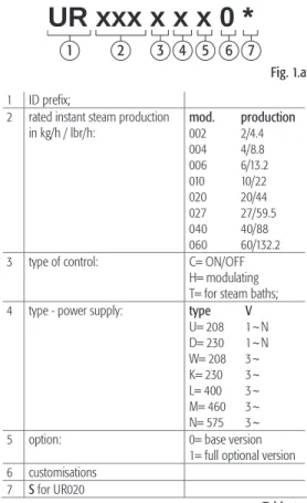
The code that defines the model of the humidifier of the electric heater consists of 10 characters, with the following meaning (Fig. 1a).
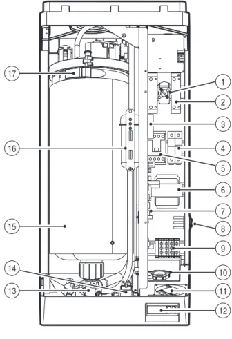
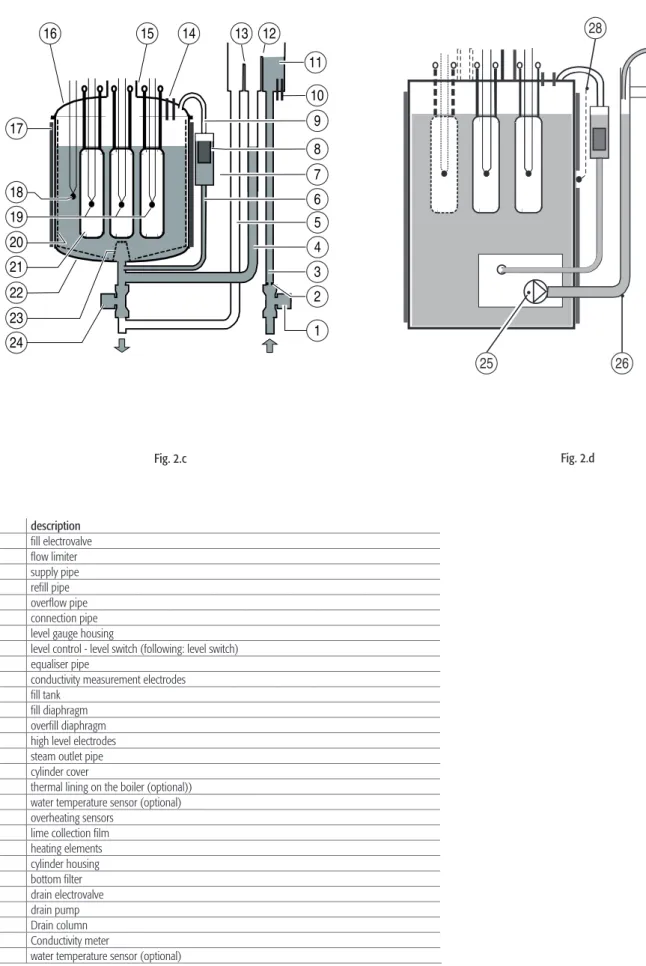
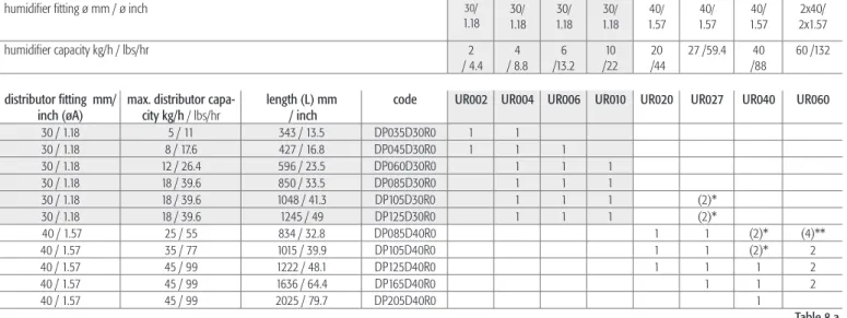
DESCRIPTION OF THE MAIN COMPONENTS AND FUNCTIONS 8
- Overfi ll device
- Control of steam production
- Measurement of supply water conductivity- alarm
- Automatic draining
- Foam elimination procedure
- Safety thermostat (Motor Protector)
- Autotest procedure
- Measurement of the water temperature and pre-heating (not available in the version with type
- Dehumidifi cation request signal (not available in the version with type C control module) .11
This is a device used to prevent water from escaping from the cylinder above a safety level, for example due to a failure of the control module (see HUMIDIFIER CONTROLLER for more details) or a leak from the charging solenoid valve. This procedure is used to repeatedly activate and deactivate (with the fill valve open) the drain valve for 1 second at the beginning of the drain cycles.
CONTROL PRINCIPLES 12
Modulating control (control module H)
Also in this case, the controller modulates steam production as a function of the %rH measurement performed by the main relative humidity transducer, but in addition its entity is limited if the relative humidity %rH2 measured by the second compensating transducer installed in the air duct behind the humidifier exceeds maximum desired value. To prevent the relative humidity measured by the transducer in the air duct downstream of the humidifier from exceeding a value considered excessive, the control module with autonomous control and another transducer connected allows the programming of the high output relative humidity alarm threshold P9. .
Setting the alarm thresholds (type H or T control module)
If this threshold is exceeded, after a programmable delay P4, an alarm condition is activated by closing the contact of the corresponding relay on the main control panel. For steam bath applications where the control probe measures temperature rather than humidity, the same considerations apply as for the Type H control module with modulating operation and autonomous control.
ASSEMBLY 14
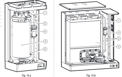
Dimensions and weights
Removing and replacing the front casing
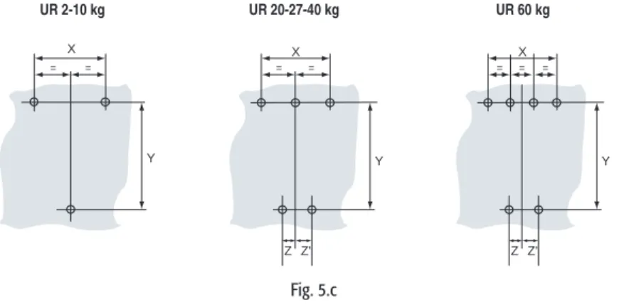
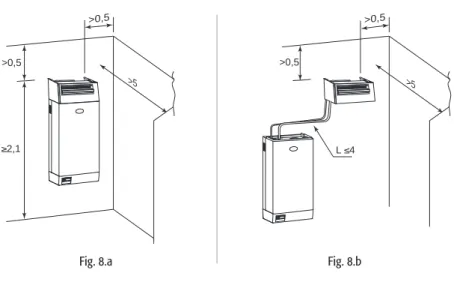
POSITIONING THE UNIT 15
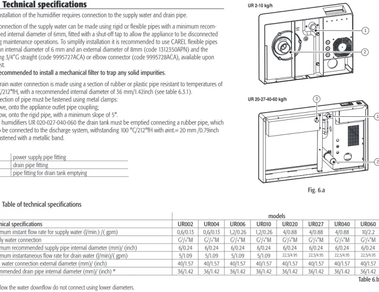
WATER CONNECTIONS 16
Characteristics of the drain water
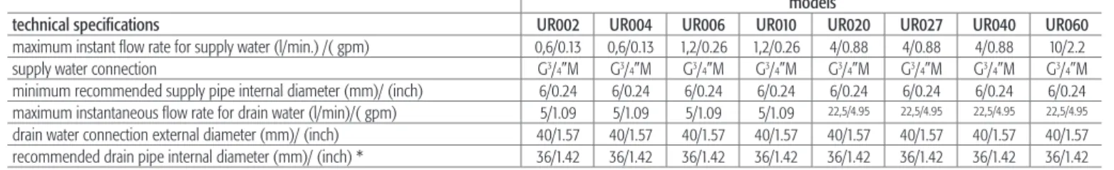
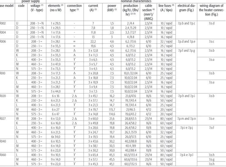
Technical specifi cations
Checks
ELECTRICAL CONNECTIONS 18
- Main control board
- Description of the terminal block and connections (functions and electrical specifi cations)
- Auxiliary connections
- Other auxiliary contacts
- Checks
- Wiring diagrams for the connection of the heating
- Single-phase wiring diagram for 2-4kg/h (4.4-8.8lbr/h) humidifi ers with type C control module
- Single-phase wiring diagram for 6kg/h (13.2lbr/h) humidifi ers with type C control module .25
- Three-phase wiring diagram for humidifi ers with type H or T control module
- Three–phase electrical diagram for 20 (44lbr/h) ( 208-230-400-460-5756V) 27-40Kg/h (59.5-
- Three–phase electrical diagram for 20 (44lbr/h) ( 208-230-400-460-5756V) 27-40Kg/h (59.5-
- Three–phase electrical diagram for 60Kg/h (132.2lbr/h) humidifi ers with type C control modu-
- Three–phase electrical diagram for 60Kg/h (132.2lbr/h)humidifi ers with type H control module
- Three–phase electrical diagram for 27Kg/h (59.5lbr/h)humidifi ers with type H control module
- Three-phase electrical diagram for 60kg/h (132.2lbr/h) humidifi ers with type H control module
- Three-phase electrical diagram for 60kg/h (132.2lbr/h) humidifi ers with type C control module
Before connecting probes or an external controller, set parameters A2 and A6 according to the control signal (see HUMIDIFIER CONTROLLER). The control module can be connected to the RS485 serial line or alternatively to the CAREL Humivisor remote control panel marked MT or to a remote supervisor. Even in this case, the humidifier can be connected via RS485 to the CAREL Humivisor MT remote control panel or a remote controller.
The reference (zero) of the external regulator must be connected to terminal 6I on terminal I, and the control signal to terminal 5I (Figure 5.e). To avoid control interference, the ground of the external controller must be connected to the ground of the controller. With this configuration (see Figure 7.f), the main control panel connected to the HT humidity probe performs full control based on the measured humidity.
The control can be connected to non-CAREL active probes; see Using Probes of Different Brands. The control signal must be connected to terminal 5I, whose reference (GND) is represented by terminal 6I. Connection to the alarm switch (250 Vac; maximum load: 8 A resistive - 2 A inductive) is made using the removable terminal block H, as in fig.
The connection to the dehumidification contact (250 Vac; maximum load: 8 A resistive - 2 A inductive) is made using the removable terminal block G, as shown in Fig.
STEAM DISTRIBUTION 37
- Steam distribution in cold rooms
- Ducted steam distribution: linear and concentrated jet distributors (OEM)
- Concentrated jet steam distribution (OEM) (only for humidifi ers up to 10 Kg/h/22 lbr/h)
- Positioning linear distributors in the air duct
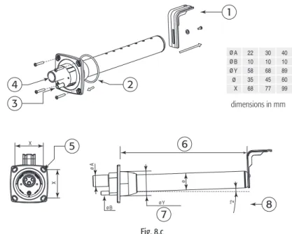
- Installation of the steam pipe
- Installing the condensate return pipe
- Checks
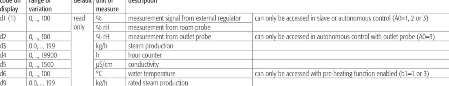
For the distribution of steam in the air ducts, the steam distributor must be properly proportional to the power of the humidifier and the cross-section of the ducts. Distributors must be as long as possible in relation to the dimensions of the air duct and placed away from bends, branches, cross-section changes, grilles, filters, fans. Refer to the placement and distances between the manifold and the duct walls and/or between two manifolds as shown in the following drawings.
The shape of the pipe must be such as to prevent the accumulation of condensate and, as a result, noise (in the form of bubbling) and loss of efficiency; the pipe run must use gravity to drain the recondensed steam back into the cylinder or manifold. Fasten the ends of the hoses to the connections on the humidifier and the steam distributor with screw clamps so that they do not loosen due to temperature. Due to the re-condensation of part of the steam produced, condensate forms in the steam supply pipe and inside the manifold, which must be drained to prevent bubbling and loss of efficiency.
To avoid the release of non-condensable steam through the condensate pipe, a trap should be created by twisting a part of the drain pipe. The end of the condensate pipe can be connected to the nearest drain, with a minimum slope of 5° to help lowering (see Fig. 8.h).
START-UP 41
Removing the heating element centring spring (only for three-phase models)
Start-up
THE HUMIDIFIER CONTROLLER 42
Type H or T control module, numeric LED display, modulating action
7 LED for multiplying by a thousand the value shown on the screen 8 LED indicating the activation of the dehumidification relay. When the humidifier is turned on, the turn-on sequence occurs, signaled by the flashing of the LEDs, as described below. In case of an active alarm, the LED next to the ALARM sign lights up and the display shows the corresponding code.
Pressing the SEL button displays the unit of measurement of the displayed measurement for one second. Pressing the Δ button displays the measurement from probe 1 (if present), preceded by the corresponding unit of measurement by 1 second. Pressing the ∇ button will display the measurement from probe 2 (if present), preceded by the corresponding unit of measurement by 1 second.
In the event of an alarm condition, LED 9 (see Fig. 10.a) starts flashing, while the display shows the alphanumeric alarm code alternating every 2 seconds with the programmed value of the functional parameter. If more than one alarm is displayed, the display will show all associated codes sequentially at 2 second intervals.
READING AND PROGRAMMING THE PARAMETERS OF THE TYPE H OR T
- Display of SW release
- Reading and programming the control parameters - reading the measurements
- Reading and programming the confi guration parameters
- Validity of the modifi cations to the parameters
- Recalling the default parameters (factory settings)
- Resetting the hour counter
- Displaying and modifying the unit of measure
- Automatic total drain for inactivity
- User-adjustable duration of dilution drain
- User-adjustable max. allowed no. of evaporation cycles between 2 dilution drains
- Reduced fi lls to restore water level after evaporation
- PWM fi lls after dilution and high-level/foam drains
Press the SEL button to display the value of the selected parameter; 3. unit of measure of the button Δ or ∇ to change the value; holding down one of the buttons increases the scrolling speed (see Figure 11.e);. These parameters can only be accessed with a password to prevent unwanted configuration changes.
Press the SEL button to display the value of the selected parameter; unit of measurement of 5. Press the SEL button to confirm the displayed value; the identification code Ax, bx or Cx of the 7 selected. We recommend setting bD= 0 after a very careful assessment of water quality and consequences.
The steam flow is negatively affected by the greater amount of fresh water introduced after the drain. The duration of the filling can be reduced by the new user parameter bA which defines the new duration as a % of the internally set standard duration: new duration= standard duration x bA / 100.
THE REMOTE CONTROL (OPTIONAL ACCESSORY) 52
Programming from the remote control
To activate or deactivate the access code for using the remote control, enter the configuration mode of the control module with password 77 (see Reading and programming the configuration parameters). Assigning parameter C2 to a value other than 0 (from 01 to 99) will activate this number as the access code that must be entered each time the remote is used to program that device. If parameter C2 is reset to 0, the remote control can be used without the need for the access code.
When not in the programming phase, the SEL (limited to the display of the measuring unit), PRG (limited to the function of alarm reset) and only the display buttons are always active. All devices placed within the range of the remote control will display their own password. To access the programming/reading routine, use the numeric keypad (Fig. 12.b) to enter the password for the machine to be operated.
Any zeros must be included (ex: if the display shows 05, press the 0 and then the 5 button). The values in the memory of the controller are changed automatically when you exit the programming phase.
Exiting the programming phase
SHUTTING DOWN THE UNIT 55
For proper operation, the steam production cylinder must be cleaned periodically, at intervals related to the amount of salts or impurities dissolved in the feed water. This operation is necessary because the scale deposits that form hinder the exchange of heat between the elements and the water. IMPORTANT WARNING: Do not use detergents or solvents to clean the parts in the cylinder and all other lines.
Remove the non-stick coating (optional), if present, from the inner wall of the cylinder and remove 12. For the power connections, follow: Electrical diagram of the heating element connection corresponding to the heads.
ALARMS AND TROUBLESHOOTING 58
Troubleshooting
HUMIDIFIER TECHNICAL SPECIFICATIONS 61
Replacing the components
If required as an option, the inner wall of the cylinder is coated with a non-stick film to avoid lime depositing on the inner walls of the cylinder. To replace the elements, remove the cylinder following the procedure described in Cylinder-Cylinder Maintenance and loosen the lock nuts from the threaded tails of the elements. Before reassembling the elements, check the condition of the gaskets and replace them if necessary.
These measure 10.3 x 38 mm and are housed in the fuse cartridge; to check the condition of the fuses, check their continuity using a tester. Dimension of the fuse 27x60 mm fast, housed in fuse bearing bases that can be selected. With insufficient ventilation, the temperature of the electrical panel can rise excessively until, up to 65°C, power to the solid state relay is cut off by a special Klixon (heat sensor, used in this application as a circuit breaker - hereafter: circuit breaker), with manual reset (indicated by S2 in the wiring diagram) and without an activation signal.
Whether the thermal protection located in the din rail near the SSR relays has worked, or. In case of malfunction, the thermal protection can be replaced by removing the transparent polycarbonate protection of the solid state relays and unscrewing the fixing screws.
Spare parts
Disposal of the parts of the humidifi er