In addition, the CE mark guarantees that our equipment fully complies with the requirements of the European Machinery Directive in terms of safety. The installation instructions, together with all related documentation, must be given to the user of the system, who assumes the responsibility of keeping the instructions so that they are always at hand in case of need. The validity of the guarantee will be invalid in case of non-compliance with the above-mentioned indications.
This device is not suitable for use by persons (including children) with reduced physical, sensory or mental capabilities or those who lack experience or expertise, unless they have been given supervision or instruction concerning use of the device by a person who responsible for their safety. It is forbidden to carry out any technical or maintenance operation before the unit has been disconnected from the electrical mains by turning off the main switch of the system and the main power switch on the control panel. It is forbidden to touch the device when you are barefoot and with parts of the body that are wet or damp.
It is forbidden to open the access doors to the internal parts of the device without first switching off the main switch of the system. It is forbidden to spread or leave the packaging materials, and they must be kept out of the reach of children, as they represent a potential source of danger.
Notes regarding the documentation
Use in compliance with destination
AERMEC units are built according to the recognized technical standards and safety regulations. Despite this, dangers may arise for the user or third parties, as well as damage to the device and other objects, in the case of improper use and use that is not in accordance with what is intended.
Preservation of the documentation
Fundamental safety regulations
Product identification
Descrizione dell'unità
- Models available
- Versions available
- Silenced motorcondensers (CL)
- Configurator
01 Low static pressure storage tank and single pump 02 Low static pressure storage tank and reserve pump 03 High static pressure storage tank and single pump 04 High static pressure storage tank and reserve pump. P2 Without storage tank with low static pressure pump and reserve pump P3 Without storage tank with high static pressure.
Description of the components
- Nrl 0280-0300-0330-0350
- Nrl 0500-0550-0600-0650-0700
- Cooling circuits, hydraulic (A - E)
- Cooling circuits, hydraulic (HA - HE)
- Cooling circuit
- Frame and fans
- Hydraulic components
- Control and safety components
- Electric components
High efficiency achieved with copper tubes and aluminum fins blocked by mechanical expansion of the tubes. Used to check the refrigerant gas load and the possible presence of moisture in the cooling circuit. The mechanical valve, with external compensator located at the outlet of the evaporator, modulates the gas flow to the evaporator depending on the heat load to ensure a correct heating level of the intake gas.
Depending on the features of the pump selected, it provides a static pressure that is useful to overcome system pressure drops. Water filter (installed as standard) This allows blocking and eliminating any dirt present in the hydraulic circuits. Automatic, mounted on the upper part of the hydraulic plant; it discharges any air pockets present in it.
Its operation is controlled by the antifreeze probe placed in the plate evaporator. Activation occurs when the temperature of the water is +3°C, while it is disconnected with water temperature of +5°C.
Accessories
TP2 Allows viewing of the compressor inlet pressure value on the microprocessor board display (one per circuit). Placed on the low-pressure side of the refrigerant circuit, it inhibits the operation of the compressor if abnormal operating pressures occur. TP3 Allows viewing of compressor flow pressure values on the microprocessor board display (one per circuit).
Placed on the high-pressure side of the refrigeration circuit, it prevents compressor operation if abnormal operating pressures occur. according to standard according to standard according to standard according to standard according to standard. E according to standard according to standard according to standard according to standard according to standard. HE according to standard according to standard according to standard according to standard according to standard.
MULTICHILLER Control system for controlling, switching on/off the single chillers in a plant where several units are installed in parallel, always ensuring constant flow to the evaporators. This is a manual pressure switch electrically wired in series with the existing automatic high pressure switch on the compressor discharge pipe.
Technical data
Technical data for versions (A - E)
Aermec determines sound power values in accordance with standard 9614-2, in accordance with that required by Eurovent certification. Sound pressure measured under free field conditions with reflective surface (directivity factor Q=2) at a distance of 10 mt from the external surface of the unit, in accordance with ISO 3744 regulations.
Technical data for versions (HA - HE)
Technical data for versions (C)
Operational limits
Cooling mode functioning
Heating mode functioning
Motorcondensing functioning
Corrective coefficients
- Cooling capacity and input power
- Heating capacity and input power
- For ∆t different to the nominal
- Deposit factors
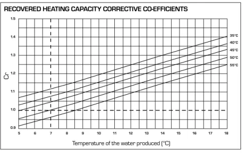
The heat capacity efficiency and electrical input power under conditions deviating from normal conditions are obtained by multiplying the nominal values (Pt, Pa) by the respective coefficient corrections (Ct, Ca). The following diagram shows how to obtain corrective coefficients; the produced hot water temperature referred to is shown in accordance with each curve, assuming a water temperature difference of 5°C between the condenser inlet and outlet. For different deposit factor values, the data in the performance tables is multiplied by the indicated coefficients.
Ethylene glycol solution
How to interpret glycol curves
Pressure drops
Total pressure drops
Total pressure drops
Storage tank
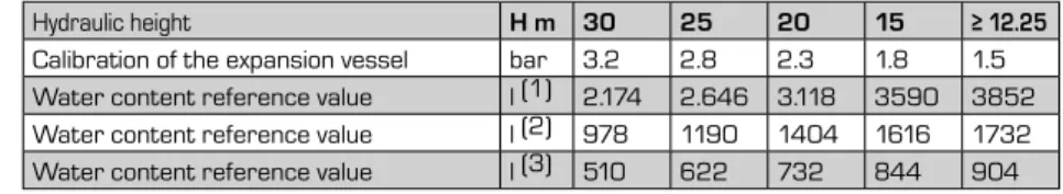
Minimum/maximum water content in the system
The values in the table refer to three maximum and minimum water temperature conditions. If the effective water capacity of the hydraulic system (including storage tank) is greater than shown in the table while it is active, an additional expansion vessel is required. From tables 12.3 it is possible to obtain the maximum content values for the system also for operating conditions with glycolyzed water.
Calibration of the expansion tank The standard preload value of the expansion tank is 1.5 bar, and their volume is 24 liters. The pan calibration should be adjusted using the user's maximum level difference (H) (see diagram) using the following formula. For example: if the level difference (H) is equal to 20 m, the calibration value of the tank will be 2.3 bar.
Minimum water content in case of process applications or applications with low outdoor temperatures and low load.
Capacity control
Desuperheater
Pressure drops
Total recovery
Nrl (T)
Pressure drops
Dimensionement cooling lines version (C)
Sound data
Calibration of control and safety parameters
Dimensions
- Nrl 0280 - 0300 - 0330 - 0350
- Minimum technical spaces nrl 0280 - 0300 - 0330 - 0350
- Anti-vibration mounts position
- Nrl 0500 - 0550 - 0600 - 0650 - 0700
- Minimum technical spaces 0500 - 0550 - 0600 - 0650 - 0700
- Anti-vibration mounts position
- Percentage of wieght distribution on supports
- Percentage of weight distribution on supports
- Percentage of wieght distribution on supports
- Percentage of weight distribution on supports
- Percentage of wieght distribution on supports
- Percentage of weight distribution on supports
PERCENTAGE OF WEIGHT DISTRIBUTION IN VERSIONS SUPPORT (TOGETHER WEIGHT) (E - HE) SUPPORT (TOGETHER WEIGHT) VERSIONS (E - HE). WEIGHT DISTRIBUTION PERCENTAGE ON SUPPORT (MACHINE WORK) VERSIONS (HA - HE) (MACHINE WORK) VERSIONS (HA - HE).
Safety warnings and installation regulations
Receiving the product
Handling
Positioning
Handling example
Hydraulic circuits
Hydraulic circuit inside nrl "00"
Hydraulic circuit inside nrl"P1-P2-P3-P4"
Hydraulic circuit inside nrl "01-02-03-04-05-06-07-08"
Hydraulic circuit inside nrl "09-10"
Filter maintenance
Procedure to follow to clean the filter
Position of hydraulic connections
Position of hydraulic connections motorcondensing version
Electrical connections
- Unit electric lines and data
- Electrical data
- Connection to the electric power supply mains
- Electric connections
Make sure the electrical line you are connecting to is not live. The figures below show the different parts used to make opening the panel easy and the different line connections.
Commissioning
Preliminary operations
Commissioning
Collect information and data and understand the status of the unit's efficiency to avoid possible malfunctions. Keep a maintenance log on the machine (not supplied with the machine, the responsibility of the user) so that you can keep track of the maintenance performed. This makes it easy to properly organize work and facilitate troubleshooting on the machine.
In the logbook you record the date, the type of work carried out (routine maintenance, inspection or repair), a description of the work, any measures taken, etc. Check the watertight integrity of the cooling circuit and that the pipes are not damaged. Check the operation of the evaporator resistance and the compressor crankcase.
Check that the screws on the fan grilles and on the fan housings, the compressors and the electrical box are tight, as well as on the outer panels of the unit. The disposal of the gas refrigerant, the glycolated water mixture, if any, and the recovery of any other material or substance must be carried out by qualified personnel in accordance with the specific regulations in force, to avoid injury to persons or damage to property. prevent. as well as the pollution of the environment. If the person is unconscious, place the person in a stable side position and consult a doctor.
Accidental opening of the electrical control panel while the machine is running is prevented by the door block isolating switch. The machine must not exceed the pressure and temperature limits indicated in the table presented in the paragraph "Operating limits" of the technical manual. Proper operation of the unit is not guaranteed after a fire; before restarting the car, have it checked by an authorized after-sales service center.
The machine is equipped with safety valves that can release high-temperature gas into the atmosphere in case of excessive pressure. Be as careful as possible when restoring the refrigerant charge indicated on the machine nameplate (inside the electrical control panel). Ensure sufficient air exchange and/or exhaust system in the workplace.
System loading unloading
Maintenance
Before starting any service or cleaning operation, be sure to disconnect the power supply from the unit.
Disposal
Disconnecting the unit
Dismantling and disposal
In case of direct contact with the liquid, warm the frozen parts with water and consult a doctor.
Improper use
Important safety information
Eye contact Flush the eyes with running water for at least 15 minutes, keeping the eyelids open.
R410A refrigerant gas
However, it can ignite if mixed with air under pressure and exposed to a strong source of ignition. The vapors are heavier than air and can cause suffocation by reducing the oxygen available for breathing. Contains gases fluorados de efecto invernadero regulados by el Protocolo de Kyoto R410A (Potencial de calentamiento atmosférico 1980).
Contém gás para o efeito fluorescente correspondente ao protocolo de Kyoto R410A (Potentiel de rêchement planétaire 1980). Contém gás flúor e tem efeito disciplinar do protocolo de Kyoto R410A (Potenziale di ricamento globale 1980). Contém gases fluorados com efeito de estufa abrangidos pelo Protocolo de Quioto R410A (Potencial de Aquecimento Global 1980).