The builder (builder, developer or installer of the final equipment) assumes all responsibility and risk in connection with the configuration of the product to achieve the expected results in relation to the specific final installation and/or furnishing. In this case, subject to specific agreements, CAREL acts as an advisor for the success of the installation/start-up/use of the machine, but in no case assumes responsibility for the correct operation of the humidifier and the final installation, if the warnings and recommendations in this manual or in other technical documentation for the product is not followed. Only qualified personnel who are aware of the necessary precautions and are able to perform the required actions correctly may install, operate or perform technical service on the product.
Do not use abrasive chemicals, solvents or aggressive detergents to clean the interior and exterior of the humidifier, unless specifically indicated in the user manual.
General description
Operating principle
Cabinet part numbers
Hose part numbers
Blower unit part numbers
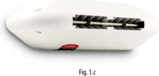
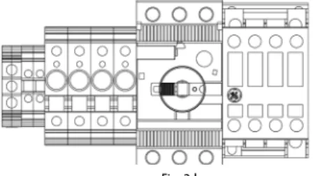
Main components
Dimensions and weights
Packaging and shipment
IP rating and standards
CABINET INSTALLATION 11
Cabinet water connections
The use of demineralized water is also required to comply with standards UNI8883, VDI6022 and VDI3803. The drain point located at the bottom of the cabinet must be connected externally (3/4" GAS F fitting) to an open drain with drain plug. Also remember that the cabinet cannot be installed on the floor without a support which keeps the cabinet raised, at least 20-30 cm.
Cabinet electrical installation
Changing the oil cap
DISTRIBUTION SYSTEM INSTALLATION 13
Mounting single blower units on the wall / ceiling
Then make the water connections by connecting the supply water line on the right or left side of the blower and the water return line on the opposite side. Carel also supplies an additional kit (including a special plate bent at 90°) to mount single blower units on the ceiling.
Mounting double blower units on the ceiling
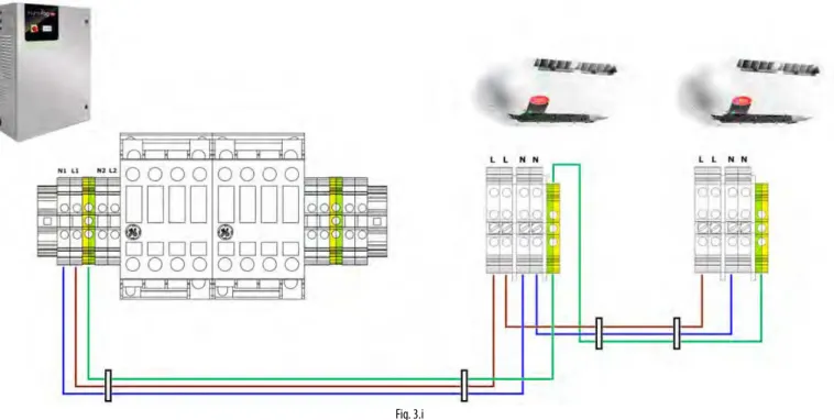
Blower unit electrical connection
ELECTRONIC CONTROLLER SET UP
- Analogue signal from the main probe and limit probe
- Analogue signal from the main probe and limit probe
- Analogue signal from an external controller
- Digital signal from humidistat or external controller
- Serial or Ethernet communication
- Alarm relay output
- Unit status digital output
- Production percentage analogue outputs
Important: Unlike the first zone, the connection to the c.pCOe extension related to the second zone can supply power to probes that require up to 21 Vdc. As an alternative to the main probe, a signal from an external controller can be used. The latter processes the request to send to the humiFog Direct via an analog signal that varies from 0 to 100%.
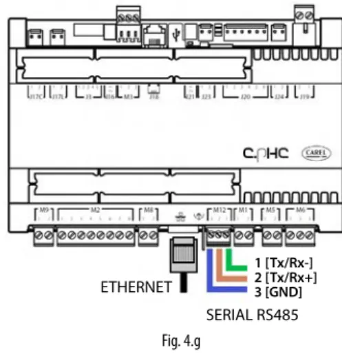
The external signal for the first zone is connected to the c.pHC controller via inputs 1 [IN a] and 2 [GND] on connector M2. The external signal for the second zone is connected to the controller c.pCOe via the inputs U1 [IN a] and [GND] on terminal J2. Make sure you configure the humiFog Direct (via the on-screen displays) so that it can be controlled by an ON/OFF signal from an external controller or device.
Modbus and BACnet communication protocols are available as standard: no auxiliary cards need to be installed in the c.pHC controller. The Ethernet port can also be used for the Webserver function (see Chapter 8), in order to monitor and control the humiFog Direct via a local network, without the need for a supervisor. The digital output for communicating an alarm status is connected to contacts 1-2-3 on terminal M6 on the c.pHC.
The c.pHC controller provides an analog output (0-10 V) corresponding to the percentage of production provided by the humiFog Direct. Important: if several GND contacts are connected to the same connector, they are equivalent to each other and can be used indifferently.
START-UP AND USER INTERFACE 19
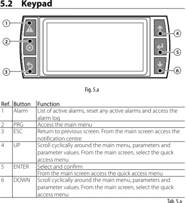
- Keypad
- Configuration wizard
- Main screen
- Graphic area 2 – Request / Probe reading
- Graphic area 3 – Notification centre
- Graphic area 4 – Unit status
- Graphic area 5 – Quick access menu
- Graphic area 6 – Zone status icon
- Alarms
This section of the main screen shows the external request signal or value measured by the main control probes for zones 1 and 2. The unit of measure shown next to the value depends on the selected control mode. Automatic start The unit started production automatically after a power failure. High temperature The water temperature in the bypass has.
Production The unit is switched on and supplies pressurized water to one or both zones. Manual Mode The unit is controlled in manual mode based on the controls sent on screens De01-De05. Backup ready The unit is ready to start operation as a backup for another unit on the network of cabinets (humidification capacity extended to a maximum of four single zone units).
This function is useful if you need to check and/or maintain the fan units in one of the two zones: while the PAUSE zone is in standby, the RUNNING zone can continue to mist on demand. Once the PAUSED zone is enabled again, nebulization immediately resumes as requested, without filling the water line. Each set point is linked to the amplitude of the proportional band within which the unit modulates the atomization.
This is a read-only menu distributed on different screens that shows the main data of the humiFog Direct device. If there are active alarms, these are displayed on the corresponding screen, accessible by pressing the dedicated button (triangle with exclamation mark).
OPERATION OPTIONS 22
- Scheduler
- Proportional control to an external signal (modulating operation)
- Autonomous control with humidity probes
- Modulation of production
Once the time periods for a day have been defined, press to copy the currently displayed time periods (daily) to the next day. The maximum production Pmax corresponds to the maximum value of the external signal Y and is the nominal production of the humidifier. When using a main humidity control probe and an optional limit humidity probe, the atomization is related to the %rH reading of the relative humidity probe and increases as the reading deviates from the setpoint St.
Maximum production Pmax corresponds to the case where the humidity value read by the probe is BP away (proportional band) from the set point. When using a main temperature sensor and an optional limit temperature sensor, the atomization is related to the temperature measurement. Maximum production Pmax corresponds to the case that the temperature value read by the probe is BP away (proportional band) from the set point.
For "Limited Humidity" or "Limited Temperature" control, a wire probe can be connected as a main probe and a wire probe as a limit. Only a group of main probes can be defined for "humidity (two probes)" or "temperature (two probes)" regulation. Wired probes can be connected to the main probe input (M2.1) and the limit probe input (M2.5), which will be used as a second probe, with a calculated average.
When using wireless probes (up to four), only a group of main probes can be defined, with the average calculated depending on the defined weight. When the atomization stops, the pump remains active and the water is recirculated through an internal bypass circuit in the pump unit, instead of being delivered to the fan units.

MASTER/SLAVE NETWORK OF HUMIDIFIERS 25
- Description of the Master/Slave system
- Network switch for Master/Slave connection
- Type of Master/Slave system installation
- Master/Slave system configuration
Connect the units that make up the Master/Slave system to the local Ethernet network via a switch. Units will join the Master/Slave (online) system immediately after being added to the network.). Note: the master unit will always (automatically) be the one with the lowest IP address from the units connected to the probes or external signal.
The “Capacity” parameter identifies the maximum production demand for the Master/Slave system and can therefore be set by the user. In contrast, the "Maximum Capacity" (read-only) parameter indicates the sum of the dimensions of each unit added to the system; this value is therefore the maximum value available for the Master/Slave system. The activation logic of the units in the Master/Slave system can be set, choosing between "Grouped" or "Balanced", on screen Dd03.
To remove a device from the Master/Slave system and thus reduce the number of available devices in the system, use the "Disconnect Device" function on screen Dd06. Note: once the device has been disconnected, it will no longer be visible in the Master/Slave system, as its IP address will be removed from the list. The units in the Master/Slave system can also be selected one by one showing maximum production, unit status, operating hours, current production request and any alarms.
Even if it is not absolutely necessary, to ensure the backup function, an external control signal must be sent to all units in the Master/Slave system; if you use probes on the other side, each unit must be equipped with a probe. During maintenance or cleaning on a unit in a Master/Slave system, you can disable the backup function for maintenance purposes.
CONNECTIVITY 28
Supervisor connection
Connecting to the serial port activates the selected protocol (Modbus or BACnet) on the displays. The default values (baudrate stop bits / no parity) should work in almost all cases, unless otherwise specified by the supervisor network installer. If connecting via Ethernet, follow the procedure (described in paragraph 8.1.1) to look up the unit's IP address, then determine whether the communication protocol will be BACnet and/or Modbus.
Important: if you use the BACnet protocol on a serial port, it cannot be used on the Ethernet port (and vice versa). The Modbus protocol on the other hand can be used simultaneously on both ports. For all other information, see the manual for the monitor used and/or contact the network manager of the monitor.
List of Modbus parameters
List of BACnet parameters
WIRELESS PROBES, INSTALLATION
Wireless probe installation
ALARM TABLE 32
- Special maintenance
- Pump maintenance
- Maintenance warning and alarm, reset hour counter
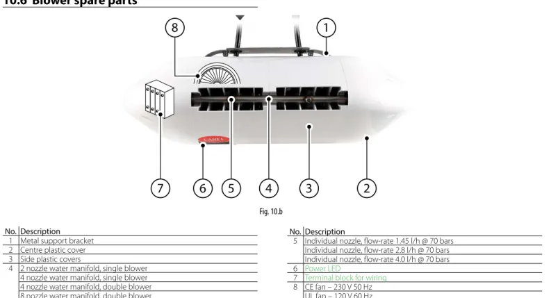
- Blower spare parts
- Cabinet spare parts
Routine maintenance is recommended every three months, and mainly involves visual inspection of the correct operation of key components. To check the level visually, use a mirror that allows a view of the side of the pump facing the cabinet wall. Check that there are no water leaks inside the cabinet and in the distribution line and equipment.
The pump is the most complex mechanical device in the cabinet, but also the heart of the high-pressure system. The passage of 3000 operating hours is signaled by the electronic controller via the alarm "3000 hours of maintenance" on the screen. Remove the yellow cap on the top of the pump and unscrew the oil drain plug at the bottom (steel hexagonal plug).
Fill the pump housing with SAE 15W40 mineral oil, up to the level indicated by the circular marker on the side of the pump (the required oil content is approximately 350 ml). The gaskets and valves must be replaced every 3000 hours, as indicated on the display by the "3000 hour maintenance" alarm. The alert can be easily reset by pressing the "Alarm" button on the user interface (top left button).
After 3000 hours of operation, on the other hand, the humiFog Direct displays a "3000 hours of maintenance" alert and the unit shuts down. In this case it is necessary to intervene in the unit, changing the oil and replacing the gaskets and valves of the pump (as described in paragraph 9.3.1 and 9.3.2).
APPENDIX 38
Two-zone cabinet wiring diagram
Datasheets
Double fan (for installation in the middle of the corridor) CE version DLA04DB*00 DLA08DB*00. Double fan (for installation in the middle of the corridor) UL version DLA04UB*00 DLA08UB*00.

![Fig. 4.d7 [GND]](https://thumb-eu.123doks.com/thumbv2/pubdocco/291104.35622/16.892.545.806.869.1147/fig-d-gnd.webp)