INDOOR UNIT
Outdoor unit service manual MUZ-BT∙VG Series (OBH850) MXZ-F∙VF Series (OBH890)
PARTS CATALOG (OBB849) CONTENTS
1. TECHNICAL CHANGES
···22. PART NAMES AND FUNCTIONS
···33. SPECIFICATION
···4
4. NOISE CRITERIA CURVES
···5
5. OUTLINES AND DIMENSIONS
···66. WIRING DIAGRAM
···77. REFRIGERANT SYSTEM DIAGRAM
···9
8. SERVICE FUNCTIONS
···10
9. MICROPROCESSOR CONTROL
··· 1310. TROUBLESHOOTING
··· 1711. DISASSEMBLY INSTRUCTIONS
··· 31SERVICE MANUAL
MSZ-BT25VG/VGK
No. OBH849
REVISED EDITION-B
OBH849 REVISED EDITION-A is void.
Revision B:
• MSZ-BT20/25/35/50VGK - E1 , ET1
have been added.
Models
MSZ-BT20VG
-
E1 , ER1, ET1MSZ-BT20VGK
-
E1 , ET1MSZ-BT25VG
-
E1 , ER1, ET1MSZ-BT25VGK
-
E1 , ET1MSZ-BT35VG
-
E1 , ER1, ET1MSZ-BT35VGK
-
E1 , ET1MSZ-BT50VG
-
E1 , ER1, ET1MSZ-BT50VGK
-
E1 , ET1Use the specified refrigerant only
Never use any refrigerant other than that specified.
Doing so may cause a burst, an explosion, or fire when the unit is being used, serviced, or disposed of.
Correct refrigerant is specified in the manuals and on the spec labels provided with our products.
We will not be held responsible for mechanical failure, system malfunction, unit breakdown or accidents caused by failure to follow the instructions.
TECHNICAL CHANGES 1
MSZ-BT20VG -
E1 , ER1 , ET1MSZ-BT25VG -
E1 , ER1 , ET1MSZ-BT35VG -
E1 , ER1 , ET1MSZ-BT50VG -
E1 , ER1 , ET1MSZ-BT20VGK -
E1 , ET1MSZ-BT25VGK -
E1 , ET1MSZ-BT35VGK -
E1 , ET1MSZ-BT50VGK -
E1 , ET11. New model
<Preparation before the repair service>
Prepare the proper tools.
Prepare the proper protectors.
Provide adequate ventilation.
After stopping the operation of the air conditioner, turn off the power-supply breaker and remove the power plug.
Discharge the capacitor before the work involving the electric parts.
<Precautions during the repair service>
Do not perform the work involving the electric parts with wet hands.
Do not pour water into the electric parts.
Do not touch the refrigerant.
Do not touch the hot or cold areas in the refrigeration cycle.
When the repair or the inspection of the circuit needs to be done without turning off the power, exercise great caution not to touch the live parts.
Revision A:
• MSZ-BT20/25/35/50VG - ER1 have been added.
Revision B:
• MSZ-BT20/25/35/50VGK - E1 , ET1 have been added.
PART NAMES AND FUNCTIONS 2
MSZ-BT20VG MSZ-BT25VG MSZ-BT35VG MSZ-BT50VG MSZ-BT20VGK MSZ-BT25VGK MSZ-BT35VGK MSZ-BT50VGK
ACCESSORIES
Model
MSZ-BT20VG MSZ-BT20VGK MSZ-BT25VG MSZ-BT25VGK MSZ-BT35VG MSZ-BT35VGK MSZ-BT50VG MSZ-BT50VGK
Installation plate 1
Installation plate fixing screw 4 × 25 mm 5
Wireless remote controller 1
Felt tape (For left or left-rear piping) 1
Battery (AAA) for remote controller 2
Remote controller Operation indicator lamp
Remote control receiving section
Emergency operation switch Spec name plate
Horizontal vane
Air inlet
Air fi lter (Air purifying fi lter)
Air cleaning fi lter (Silver-ionized air purifi er fi lter, option)
Front panel
Air outlet Heat exchanger
Wi-Fi interface
(Only for MSZ-BT·VGK)
SPECIFICATION 3
Indoor model MSZ-BT20VG
MSZ-BT20VGK MSZ-BT25VG
MSZ-BT25VGK MSZ-BT35VG
MSZ-BT35VGK MSZ-BT50VG MSZ-BT50VGK
Power supply Single phase 230 V, 50 Hz
Electrical data
Power input 1
Cooling
W 19 31
Heating 24 37
Running current 1
Cooling
A 0.20 0.31
Heating 0.25 0.35
Fan motor
Model RC0J30-CV
Current 1 Cooling
A 0.20 0.31
Heating 0.25 0.35
Dimensions W × H × D mm 838 × 280 × 235
Weight kg 9.0
Special remarks
Air direction 5
Airflow Cooling
Super High
m3/h
654 792
High 522 660
Med. 408 540
Low 312 456
Super Low 252 378
Heating
Super High 714 846
High 540 714
Med. 408 594
Low 300 468
Super Low 252 360
Sound level Cooling
Super High
dB(A)
43 46
High 37 38 40
Med. 30 31 36
Low 22 33
Super Low 19 29
Heating
Super High 43 44 48
High 37 43
Med. 30 38
Low 23 33
Super Low 20 29
Fan speed Cooling
Super High
rpm
990 1,150
High 840 1,000
Med. 700 860
Low 580 760
Super Low 500 660
Heating
Super High 1,060 1,210
High 860 1,060
Med. 700 920
Low 560 770
Super Low 500 640
Fan speed regulator 5
Remote controller model ZH19A
NOTE: Test conditions are based on ISO 5151.
Cooling: Indoor Dry-bulb temperature 27°C Wet-bulb temperature 19°C
NOISE CRITERIA CURVES 4
MSZ-BT25VG MSZ-BT25VGK
MSZ-BT35VG
MSZ-BT35VGK MSZ-BT50VG
MSZ-BT50VGK
10 20 30 40 50 60 70 80 90
63 125 250 500 1000 2000 4000 8000
OCTAVE BAND SOUND PRESSURE LEVEL,dB re 0.0002 MICRO BAR
BAND CENTER FREQUENCIES,Hz NC-60
NC-50
NC-40
NC-30
NC-20 NC-70 COOLING
FUNCTION SPL(dB(A)) LINE 46
HEATING 44
10 20 30 40 50 60 70 80 90
63 125 250 500 1000 2000 4000 8000
NC-60
NC-50
NC-40
NC-30
NC-20 NC-70
OCTAVE BAND SOUND PRESSURE LEVEL,dB re 0.0002 MICRO BAR
BAND CENTER FREQUENCIES,Hz COOLING
FUNCTION SPL(dB(A)) LINE 46
HEATING 48
10 20 30 40 50 60 70 80 90
63 125 250 500 1000 2000 4000 8000
NC-60
NC-50
NC-40
NC-30
NC-20 NC-70
OCTAVE BAND SOUND PRESSURE LEVEL,dB re 0.0002 MICRO BAR
BAND CENTER FREQUENCIES,Hz COOLING
FUNCTION SPL(dB(A)) LINE 43
HEATING 43
Test conditions
Cooling: Dry-bulb temperature 27°C Wet-bulb temperature 19°C Heating: Dry-bulb temperature 20°C
Wet-bulb temperature 15°C
INDOOR UNIT
WALL
MICROPHONE 0.8m
1m
MSZ-BT20VG MSZ-BT20VGK
10 20 30 40 50 60 70 80 90
63 125 250 500 1000 2000 4000 8000
NC-60
NC-50
NC-40
NC-30
NC-20 NC-70
OCTAVE BAND SOUND PRESSURE LEVEL,dB re 0.0002 MICRO BAR
BAND CENTER FREQUENCIES,Hz COOLING
FUNCTION SPL(dB(A)) LINE 43
HEATING 43
OUTLINES AND DIMENSIONS 5
Unit: mm
100.5
242.5
225 225
199.537.5
100.5
52.5
167.5 167.5
366.5 327.5 91.5
3 37.5199.5 219.5 242.523.5
46 18.5
167
838
2355
280
50
(5) 351.5
66.52.5
64
43
57
42 57
164
100 12.5
126.5 98
40
57
677.5 111
(49.5)
MIN 37mm IN CASE OF LEFT, LEFT REAR,OR LEFT UNDER PIPING (USING SPACER), MIN 125mm
MIN 20mm
MIN 7mm
MIN 30mm
INSTALLATION PLATE
11×20 OBLONG HOLE 11×26 OBLONG HOLE
INDOOR UNIT WALL HOLE ø65
AIR OUT
AIR IN INSTALLATION PLATE PIPING
DRAIN HOSE
MSZ-BT20/25/35VG MSZ-BT20/25/35VGK
PIPING
INSULATION ø37 O.D
LIQUID LINE ø6.35 - 0.39m (FLARED CONNECTION ø6.35) GAS LINE ø9.52 - 0.34m (FLARED CONNECTION ø9.52) DRAIN HOSE INSULATION ø29CONNECTED PART ø16 O.D MSZ-BT50VG MSZ-BT50VGK
PIPING
INSULATION ø37 O.D
LIQUID LINE ø6.35 - 0.39m (FLARED CONNECTION ø6.35) GAS LINE ø9.52 - 0.34m (FLARED CONNECTION ø12.7) DRAIN HOSE INSULATION ø29 CONNECTED PART ø16 O.D
MSZ-BT20VG MSZ-BT25VG MSZ-BT35VG MSZ-BT50VG
MSZ-BT20VGK MSZ-BT25VGK MSZ-BT35VGK MSZ-BT50VGK
MSZ-BT20VG-
E1 , ER1MSZ-BT25VG-
E1 , ER1MSZ-BT35VG-
E1 , ER1MSZ-BT50VG-
E1, ER1WIRING DIAGRAM 6
MSZ-BT20VG-
ET1MSZ-BT25VG-
ET1MSZ-BT35VG-
ET1MSZ-BT50VG-
ET1UZAKTAN KUMANDA ALICI DEVRE KARTI İÇ ÜNİTE TERMİNAL
KARTI
DIŞ ÜNİTEYE
VARİSTÖR
TERMİNAL BLOĞU RESİSTÖR İÇ ÜNİTE ELEKTRONİK
KONTROL KARTI
Konektör Terminal bloğu NOTLAR:
1. Dış ünite elektronik kablolaması için dış ünite elektronik kablo devre şemasını referans alınız.
2. Sadece bakır beslemekablosu kullanın 3. Sembolleri gösterir
ODA SICAKLIK TERMİSTÖRÜ BORU SICAKLIK
TERMİSTÖRÜ (ANA) BORU SICAKLIK
TERMİSTÖRÜ (YARDIMCI)
SİGORTA (T3.15AL250V) FAN MOTORU KANAT MOTORU
(YATAY)
RÖLE
PARÇA ADI
MSZ-BT20VGK-
E1MSZ-BT25VGK-
E1MSZ-BT35VGK-
E1MSZ-BT50VGK-
E1MSZ-BT20VGK-
ET1MSZ-BT25VGK-
ET1MSZ-BT35VGK-
ET1MSZ-BT50VGK-
ET1İÇ ÜNİTE TERMİNAL
KARTI İÇ ÜNİTE ELEKTRONİK
KONTROL KARTI
VARİSTÖR
TERMİNAL BLOĞU RESİSTÖR
ODA SICAKLIK TERMİSTÖRÜ BORU SICAKLIK TERMİSTÖRÜ (ANA)
BORU SICAKLIK TERMİSTÖRÜ (YARDIMCI)
SİGORTA (T3.15AL250V)
FAN MOTORU
KANAT MOTORU (YATAY) PARÇA ADI
RÖLE
REFRIGERANT SYSTEM DIAGRAM 7
Unit: mm
MSZ-BT20VG MSZ-BT25VG MSZ-BT20VGK MSZ-BT25VGK
Indoor
heatexchanger Flared connection
Room temperature thermistor
RT11 Flared connection
Refrigerant pipe ø9.52 (with heat insulator)
Refrigerant pipe ø6.35 (with heat insulator) Indoor coil
thermistor RT12
Indoor coil thermistor RT13
Refrigerant flow in cooling Refrigerant flow in heating
MSZ-BT35VG MSZ-BT50VG MSZ-BT35VGK MSZ-BT50VGK
Indoor
heatexchanger Flared connection
Room temperature thermistor RT11
Flared connection
Refrigerant pipe ø6.35 (with heat insulator) Indoor coil
thermistor RT12
Refrigerant pipe ø 9.52 (MSZ-BT35VG/VGK) ø12.7 (MSZ-BT50VG/VGK) (with heat insulator)
Indoor coil thermistor RT13
Refrigerant flow in cooling Refrigerant flow in heating
MSZ-BT20VG MSZ-BT25VG MSZ-BT35VG MSZ-BT50VG MSZ-BT20VGK MSZ-BT25VGK MSZ-BT35VGK MSZ-BT50VGK
8-1. TIMER SHORT MODE
For service, the following set time can be shortened by bridging the timer short mode point on the electronic control P.C.
board. (Refer to 10-7.)
• The set time for the ON/OFF timer can be reduced to 1 second for each minute.
• After the breaker is turned on, the time for starting the compressor, which normally takes 3 minutes, can be reduced to 1 minute. Restarting the compressor, which takes 3 minutes, cannot be reduced.
SERVICE FUNCTIONS 8
8-2. HOW TO SET REMOTE CONTROLLER EXCLUSIVELY FOR A PARTICULAR INDOOR UNIT
A maximum of 4 indoor units with wireless remote controllers can be set.To operate the indoor unit individually with each remote controller, assign a number to each remote controller according to the number of the indoor unit.
Set according to the following procedure:
(1) Turn the breaker OFF for the unit.
(2) With the remote controller powered OFF, hold down UNIT button on the remote controller for 2 seconds to enter the pairing mode.
Setting number is displayed in the remote controller.
(3) Press UNIT button again and assign a number to each remote controller.
Each press of UNIT button advances the number in the following order: 1→2→3→4.
(4) Press to OPERATION SELECT( ) button complete the pairing setting.
After you turn the breaker ON, the remote controller that first sends a signal to an indoor unit will be regarded as the remote controller for the indoor unit.
Once they are set, the indoor unit will only receive the signal from the assigned remote controller afterwards.
The setting of indoor unit will be cancelled, if the breaker is turned OFF or the power supply is shut down.
8-3. AUTO RESTART FUNCTION
When the indoor unit is controlled with the remote controller, the operation mode, the set temperature, and the fan speed are memorized by the indoor electronic control P.C. board. “AUTO RESTART FUNCTION” automatically starts operation in the same mode just before the shutoff of the main power.
Operation
If the main power has been cut, the operation settings remain.
After the power is restored, the unit restarts automatically according to the memory.
(However, it takes at least 3 minutesfor the compressor to start running.)
How to disable “AUTO RESTART FUNCTION”
Turn off the main power for the unit.
Cut the jumper wire to JR77 on the indoor electronic control P.C. board. (Refer to 10-7.)
NOTE:
• The operation settings are memorized when 10 seconds have passed after the indoor unit was operated with the remote controller.
• If main power is turned OFF or a power failure occurs while AUTO START/STOP timer is active, the timer setting is can- celled.
• If the unit has been turned OFF with the remote controller before power failure, the auto restart function does not work as the power button of the remote controller is OFF.
• To prevent the breaker from tripping OFF due to the rush of starting current, systematize other home appliance not to turn ON at the same time.
• When some air conditioners are connected to the same supply system, if they are operated before power failure, the starting current of all the compressors may flow simultaneously at restart.
Therefore, the special counter-measures are required to prevent the main voltage-drop or the rush of the starting current by adding to the system that allows the units to start one by one.
JR77 Indoor electronic control P.C. board
CN111CN151
GND
CN112
34 56
2 1
• Ensure that the Router supports the WPA2-AES encryption setting before starting the Wi-Fi interface setup.
• The End user should read and accept the terms and conditions of the Wi-Fi service before using this Wi-Fi interface.
• To complete connection of this Wi-Fi interface to the Wi-Fi service, the Rout- er may be required.
• This Wi-Fi interface will not commence transmission of any operational data from the system until the End user registers and accepts the terms and con- ditions of the Wi-Fi service.
• This Wi-Fi interface should not be installed and connected to any Mitsubishi Electric system which is to provide application critical cooling or heating.
• At the time of relocation or disposal, reset the Wi-Fi interface to the factory default.
ERR NETMODE UNIT RESET MODE
Wi-FiINTERFACE MODELMAC-123IFB-E MAC IDSSID KEY
: AABBCC112233 : 1812280001 : ME-A123456789 : ABCDEF123456 VOLTAGE CURRENT: 12.7V: 0.16A MITSUBISHI ELECTRIC CORPRATION
WiFi.ASSY DWG No.
DK00J098B01 MADE IN CHINAJG79C123H01>PP<
34 56
1 2
This Wi-Fi interface communicates the status information and controls the commands from the MELCloud by connecting to an indoor unit.
(1) MODE switch
• The MODE switch is used for selecting modes in configurations.
(2) RESET switch
• Hold down the RESET switch for 2 seconds to reboot the system.
• Hold down the RESET switch for 14 seconds to initialize the Wi-Fi interface to the factory default.
(1) Open the front panel and remove the Wi-Fi interface.
(2) Set up a connection between the Wi-Fi interface and the router.
Refer to the SETUP MANUAL and SETUP QUICK REFERENCE GUIDE provided with the unit.
For SETUP MANUAL, please go to the website below.
http://www.melcloud.com/Support
(3) Put the Wi-Fi interface back and close the front panel after the setup is completed.
(4) For MELCloud User Manual, please go to the website below.
http://www.melcloud.com/Support NOTE:
Mitsubishi Electric’s Wi-Fi interface is designed for communication to Mit- subishi Electric’s MELCloud Wi-Fi service.
Third party Wi-Fi interfaces cannot be connected to MELCloud.
Mitsubishi Electric is not responsible for any (i) under performance of a sys- tem or any product; (ii) system or product fault; or (iii) loss or damage to any system or product; which is caused by or arises from connection to and/or use of any third party Wi-Fi interface or any third party Wi-Fi service with Mitsubishi Electric equipment.
For the latest information regarding MELCloud from Mitsubishi Electric Corporation, please visit www.MELCloud.com.
NOTE:
When the Wi-Fi interface is reset to the factory default, ALL the configuration information will be lost. Take great care in implementing this operation.
No. Item Description
1 MODE switch It selects modes.
2 RESET switch It resets the system and ALL settings.
3 ERR LED (Orange) It shows the network error state.
4 NET LED (Green) It shows the network state.
5 MODE LED (Orange) It shows the Access point mode state.
6 UNIT LED (Green) It shows the indoor unit state.
Wi-Fi interface introduction
Wi-Fi interface Front panel
Wi-Fi interface Front panel
8-4. Wi-Fi INTERFACE SETTING UP (MSZ-BT·VGK)
WIRELESS REMOTE CONTROLLER
NOTE: Last setting will be stored after the unit is turned OFF with the remote controller. Indoor unit receives the signal of the remote controller with beeps.
Operation Indicator lamp
The operation indicator at the right side of the indoor unit indicates the operation state.
•The following indication applies regardless of shape of the indication.
INDOOR UNIT DISPLAY SECTION
button
Signal transmitting section
Operation display section
Temperature buttons
OFF/ON (stop/operate) FAN speed
control button
Operation select button
ECONO COOL button
UNIT button TIME, TIMER set buttons
forward button backward button RESET button CLOCK button
NIGHT MODE button Distance of signal : About 6 m
Beep(s) is (are) heard from the indoor unit when the signal is received.
ON-timer button OFF-timer button
i save button VANE control button Battery replacement
indicator
MICROPROCESSOR CONTROL 9
Indication Operation state Room temperature
The unit is operating to reach the set temperature
About 2°C or more away from set temperature The room temperature is
approaching the set tem- perature
About 1 to 2°C from set temperature
Standby mode (only during
multi system operation) -
Lit Blinking Not lit
MSZ-BT20VG MSZ-BT25VG MSZ-BT35VG MSZ-BT50VG
MSZ-BT20VGK MSZ-BT25VGK MSZ-BT35VGK MSZ-BT50VGK
9-2. DRY ( ) OPERATION
(1) Press OFF/ON (stop/operate) button.
OPERATION INDICATOR lamp of the indoor unit turns on with a beep tone.
(2) Select DRY mode with Operation select button.
(3) The set temperature is determined from the initial room temperature.
1. Coil frost prevention
Coil frost prevention works the same way as that in COOL mode. (9-1.1.) 2. Low outside temperature operation
Low outside temperature operation works the same way as that in COOL mode. (9-1.2.)
9-1. COOL ( ) OPERATION
(1) Press OFF/ON (stop/operate) button.
OPERATION INDICATOR lamp of the indoor unit turns on with a beep tone.
(2) Select COOL mode with Operation select button.
(3) Press Temperature buttons (TOO WARM or TOO COOL button) to select the desired temperature. The setting range is 16 - 31°C.
1. Coil frost prevention
The compressor operational frequency is controlled by the temperature of the indoor heat exchanger to prevent the coil from frosting.
When the temperature of indoor heat exchanger becomes too low, the coil frost prevention mode works.
The indoor fan operates at the set speed and the compressor stops. This mode continues until the temperature of indoor heat exchanger rises.
2. Low outside temperature operation
When the outside temperature is lower, low outside temperature operation starts, and the outdoor fan slows or stops.
9-3. FAN( )OPERATION
(1) Press OFF/ON (stop/operate) button.
OPERATION INDICATOR lamp of the indoor unit turns ON with a beep tone.
(2) Select FAN mode with Operation select button.
(3) Select the desired fan speed. When AUTO, it becomes Low.
Only indoor fan operates. Outdoor unit does not operate.
9-4. HEAT ( ) OPERATION
(1) Press OFF/ON (stop/operate) button.
OPERATION INDICATOR lamp of the indoor unit turns on with a beep tone.
(2) Select HEAT mode with Operation select button.
(3) Press Temperature buttons (TOO WARM or TOO COOL button) to select the desired temperature.
The setting range is 10 ~ 31°C.
1. Cold air prevention control
When the compressor is not operating or is starting, and the temperature of indoor heat exchanger and/or the room tem- perature is low or when defrosting is being done, the indoor fan will stop or rotate in Very Low speed.
2. High pressure protection
The compressor operational frequency is controlled by the temperature of the indoor heat exchanger to prevent the con- densing pressure from increasing excessively.
When the temperature of indoor heat exchanger becomes too high, the high pressure protection works.
The indoor fan operates following the cold air prevention control. This mode continues until the temperature of indoor heat exchanger falls.
3. Defrosting
Defrosting starts when the temperature of outdoor heat exchanger becomes too low.
The compressor stops once, the indoor/outdoor fans stop, the 4-way valve reverses, and the compressor re-starts.
This mode continues until the temperature of outdoor heat exchanger rises or the fixed time passes.
9-5. MULTI SYSTEM OPERATION
FOR MULTI SYSTEM AIR CONDITIONER OUTDOOR UNIT: MXZ seriesMulti system air conditioner can connect 2 or more indoor units with 1 outdoor unit.
• When you try to operate 2 or more indoor units with 1 outdoor unit simultaneously, one for the cooling and the others for heating, the operation mode of the indoor unit that operates first is selected. Other indoor units cannot operate, and operation indicator lamp blinks as shown in the figure below. In this case, please set all the indoor units to the same operation mode.
• When indoor unit starts the operation while the defrosting of outdoor unit is being done, it takes a few minutes (max.
10 minutes) to blow out the warm air.
• In the heating operation, though indoor unit is not operating, it may get warm or the sound of refrigerant flow may be heard. It is not malfunction. The reason is that the refrigerant continuously flows into it.
OPERATION INDICATOR
Lit Blinking Not lit
(7) SWING ( ) mode
By selecting SWING mode with VANE control button, the horizontal vane swings vertically.
(8) ECONO COOL ( ) operation (ECONOmical operation)
When ECONO COOL button is pressed in COOL mode, set temperature and the air flow direction is automati- cally changed by the microprocessor. However, the temperature on the LCD screen on the remote controller is not changed. Also the horizontal vane swings in various cycle.
SWING operation makes you feel cooler than set temperature. So, even though the set temperature is higher, the air conditioner can keep comfort. As a result, energy can be saved.
To cancel this operation, select a different mode or press one of the following buttons in ECONO COOL operation:
ECONO COOL, VANE control button.
(5) STOP (operation OFF) and ON TIMER standby
In the following cases, the horizontal vane returns to the closed position.
(a) When OFF/ON (stop/operate) button is pressed (POWER OFF).
(b) When the operation is stopped by the emergency operation.
(c) When ON TIMER is ON standby.
(6) Dew prevention
During COOL or DRY operation with the vane angle at Angle 3 to 5 when the compressor cumulative operation time exceeds 1 hour, the vane angle automatically changes to Angle 2 for dew prevention.
9-6. AUTO VANE OPERATION
1. Horizontal vane(1) Vane motor drive
These models are equipped with a stepping motor for the horizontal vane. The rotating direction, speed, and angle of the motor are controlled by pulse signals (approximately 12 V) transmitted from indoor microprocessor.
(2) The horizontal vane angle and mode change as follows by pressing VANE control button.
(AUTO) (1) (2) (3) (4) (5) (SWING)
(3) Positioning
To confirm the standard position, the vane moves until it touches the vane stopper. Then the vane is set to the selected angle.
Confirmation of standard position is performed in the following cases:
(a) When the operation starts or finishes (including timer operation).
(b) When the test run starts.
(c) When standby mode (only during multi system operation) starts or finishes.
(4) VANE AUTO ( ) mode
In VANE AUTO mode, the microprocessor automatically determines the vane angle to make the optimum room tem- perature distribution.
Horizontal position
In COOL and DRY operation
Vane angle is fixed to Horizontal position.
In HEAT operation
Vane angle is fixed to Angle 5.
5
9-7. TIMER OPERATION (ON/OFF TIMER)
1. How to set the timer(1) Press or during operation to set the timer.
(2) (ON timer) : The unit turns ON at the set time.
(OFF timer) : The unit turns OFF at the set time.
(3) Press (forward) and (backward) to set the time of timer.
9-8. EMERGENCY/TEST OPERATION
In the case of test run operation or emergency operation, use EMERGENCY OPERATION switch in the right side of the indoor unit. Emergency operation is available when the remote controller is missing or has failed, or when the batteries in the remote controller are running down. The unit will start and OPERATION INDICATOR lamp will light up.
The first 30 minutes of operation is the test run operation. This operation is for servicing. The indoor fan runs at High speed and the temperature control does not work.
After 30 minutes of test run operation, the system shifts to EMERGENCY COOL/HEAT MODE with a set temperature of 24°C. The fan speed shifts to Medium. The coil frost prevention works even in the test run or the emergency operation.
In the test run or emergency operation, the horizontal vane operates in VANE AUTO ( ) mode.
Emergency operation continues until EMERGENCY OPERATION switch is pressed once or twice or the unit receives any signal from the remote controller. In the latter case, normal operation will start.
NOTE: Do not press EMERGENCY OPERATION switch during normal operation.
Operation mode COOL/HEAT Set temperature 24°C
Fan speed Medium
Horizontal vane Auto
The operation mode is indicated by the Operation Indicator lamp as following Operation Indicator lamp
EMERGENCY COOL
↓
EMERGENCY HEAT
↓
STOP
Lit Not lit EMERGENCY OPERATION switch
9-9. 3-MINUTE TIME DELAY OPERATION
When the system turns OFF, compressor will not restart for 3 minutes as 3-minute time delay function operates to protect compressor from overload.
10-1. CAUTIONS ON TROUBLESHOOTING
1. Before troubleshooting, check the following1) Check the power supply voltage.
2) Check the indoor/outdoor connecting wire for miswiring.
2. Take care of the following during servicing
1) Before servicing the air conditioner, be sure to turn OFF the main unit first with the remote controller, and after confirm- ing the horizontal vane is closed, turn OFF the breaker and/or disconnect the power plug.
2) Be sure to turn OFF the power supply before removing the front panel, the cabinet, the top panel, and the P.C. board.
3) When removing the P.C. board, hold the edge of the board with care NOT to apply stress on the components.
4) When connecting or disconnecting the connectors, hold the connector housing. DO NOT pull the lead wires.
TROUBLESHOOTING 10
Lead wiring Connector housing
<Incorrect> <Correct>
3. Troubleshooting procedure
1) Check if the OPERATION INDICATOR lamp on the indoor unit is blinking ON and OFF to indicate an abnormality.
To make sure, check how many times the OPERATION INDICATOR lamp is blinking ON and OFF before starting ser- vice work.
2) Before servicing, check that the connector and terminal are connected properly.
3) When the electric control P.C. board seems to be defective, check the copper foil pattern for disconnection and the components for bursting and discoloration.
4) When troubleshooting, Refer to 10-2, 10-3 and 10-4.
NOTE: 1. If RESET button is not pressed, the remote controller may not operate correctly.
2. This remote controller has a circuit to automatically reset the microprocessor when batteries are replaced.
This function is equipped to prevent the microprocessor from malfunctioning due to the voltage drop caused by the battery replacement.
3. Do not use the leaking batteries.
Press RESET button with a thin instrument, and then use the remote controller.
Remove the front lid and insert batteries.
Then reattach the front lid.
4. How to replace batteries
Weak batteries may cause the remote controller malfunction.
In this case, replace the batteries to operate the remote controller normally.
1.
Remove the front lid.2.
Insert the negative pole of AAA alkaline batteries fi rst.3.
Install the front lid.4.
Press RESET.1.
Press CLOCK.3.
Press CLOCK again.2.
Press the TIME buttons to set the time.Each press changes the clock 1 minute forward/backward (10 minutes when pressed longer).
MSZ-BT20VG MSZ-BT25VG MSZ-BT35VG MSZ-BT50VG
MSZ-BT20VGK MSZ-BT25VGK MSZ-BT35VGK MSZ-BT50VGK
10-2. FAILURE MODE RECALL FUNCTION
Outline of the functionThis air conditioner can memorize the abnormal condition which has occurred once.
Even though LED indication listed on the troubleshooting check table (10-4.) disappears, the memorized failure details can be recalled.
1. Flow chart of failure mode recall function for the indoor/outdoor unit
Does left lamp of OPERATION INDICATOR lamp on the indoor unit blink at the interval of 0.5 sec- onds?
Blinks: Either indoor or outdoor unit is abnormal.
Beep is emitted at the same timing as the blinking of left lamp of OPERATION INDICATOR lamp. 2
Indoor unit is normal.
But the outdoor unit might be abnormal because there are some abnor- malities that can not be recalled with this way.
Check if outdoor unit is abnormal according to the detailed outdoor unit failure mode recall function.
No
Yes Judgment of indoor/outdoor abnormality
Before blinking, does left lamp of OPERATION INDICA- TOR lamp stay ON for 3 seconds?
Stays ON for 3 seconds (without beep):
The outdoor unit is abnormal.
The indoor unit is abnormal.
Check the blinking pattern, and identify the abnormal point by referring to the table of indoor unit failure mode recall function. (Refer to 10-2.2)
Make sure to check at least 2 consecutive blinking cycles. 2 Releasing the failure mode recall function
Release the failure mode recall function by the following procedures.
Turn OFF the power supply and turn it ON again.
Press RESET button of the remote controller.
The outdoor unit is abnormal.
Check the blinking pattern, and identify the abnormal point by referring to the table of outdoor unit failure mode recall function. (Refer to outdoor unit service manual.)
Make sure to check at least 2 consecutive blinking cycles. 3
Repair the failure parts.
Deleting the memorized abnormal condition
After repairing the unit, recall the failure mode again according to "Setting up the failure mode recall function" mentioned above.
Press OFF/ON (stop/operate) button of the remote controller (the set temperature is displayed) with the remote controller headed towards the indoor unit.
Press EMERGENCY OPERATION switch so that the memorized abnormal condition is deleted.
Release the failure mode recall function according to "Releasing the failure mode recall function"
mentioned above.
Yes (Blinks)
No (OFF)
NOTE: 1. Make sure to release the failure mode recall function after it is set up, otherwise the unit cannot operate properly.
2. If the abnormal condition is not deleted from the memory, the last abnormal condition is kept memorized.
The cause of abnormality cannot be found because the abnormality does not recur.
Setting up the failure mode recall function Turn ON the power supply.
<Preparation of the remote controller>
While pressing Operation select button and button on the remote controller at the same time, press RESET button.
First, release RESET button.
Hold down the other 2 buttons for another 3 seconds. Make sure that the indicators on the LCD screen shown in the right figure are all displayed. Then release the but- tons.
Press OFF/ON (stop/operate) button of the remote controller (the set temperature is displayed) with the remote controller headed towards the indoor unit. 1 Operational procedure
1 Regardless of normal or abnormal condition, a short beep is emitted once the signal is received.
NOTE: It takes up to 1 minute to indicate the outdoor unit abnormality.
Even if the OPERATION INDICATOR lamp is not lighting, keep checking at least 1 minute or longer.
WEEKLY TIMER
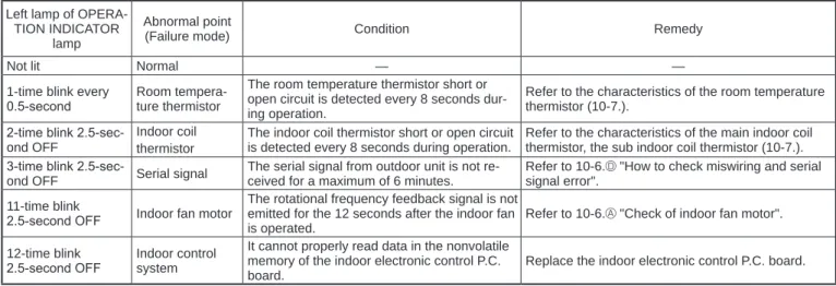
2. Table of indoor unit failure mode recall function Left lamp of OPERA-
TION INDICATOR lamp
Abnormal point
(Failure mode) Condition Remedy
Not lit Normal — —
1-time blink every
0.5-second Room tempera- ture thermistor
The room temperature thermistor short or open circuit is detected every 8 seconds dur- ing operation.
Refer to the characteristics of the room temperature thermistor (10-7.).
2-time blink 2.5-sec- ond OFF
Indoor coil thermistor
The indoor coil thermistor short or open circuit is detected every 8 seconds during operation.
Refer to the characteristics of the main indoor coil thermistor, the sub indoor coil thermistor (10-7.).
3-time blink 2.5-sec-
ond OFF Serial signal The serial signal from outdoor unit is not re- ceived for a maximum of 6 minutes.
Refer to 10-6. "How to check miswiring and serial signal error".
11-time blink
2.5-second OFF Indoor fan motor
The rotational frequency feedback signal is not emitted for the 12 seconds after the indoor fan is operated.
Refer to 10-6. "Check of indoor fan motor".
12-time blink
2.5-second OFF Indoor control system
It cannot properly read data in the nonvolatile memory of the indoor electronic control P.C.
board.
Replace the indoor electronic control P.C. board.
NOTE: Blinking patterns of this mode differ from the ones of TROUBLESHOOTING CHECK TABLE (10-4.).
10-3. INSTRUCTION OF TROUBLESHOOTING
Indoor unit operates.
Outdoor unit does not operate.
If blinking of OPERATION INDICATOR lamp cannot be checked, it can be checked with failure mode recall function.
Indoor unit operates.
Outdoor unit does not operate normally.
Indoor unit does not receive the signal from remote controller.
OPERATION INDICATOR lamp on indoor unit is blinking ON and OFF.
Outdoor unit operates only in Test Run operation.
Outdoor unit does not operate even in Test Run operation.
Unit does not operate nor- mal operation in COOL or HEAT mode.
Indoor unit does not operate, when EMERGENCY OPERATION switch is pressed.
Indoor unit operates, when EMERGENCY OPERATION switch is pressed.
Check room temperature thermistor.
Refer to 10- 7. "Test point diagram and voltage".
Refer to "How to check inverter/com- pressor".
Refer to
"Check of R.V.
coil".
Refer to 10-6.
"Check of remote controller and indoor electronic control P.C. board".
1. Check indoor/outdoor connect- ing wire.
2. Check if the power is supplied to indoor unit.
• If power supply voltage is detected, refer to 10-6. "Check of indoor P.C. board and indoor fan motor".
• If power supply voltage is not detected, refer to outdoor unit service manual.
Left lamp blink on and off at 0.5-second intervals Cause:
Indoor/Outdoor unit
• Miswiring or trouble of serial signal
Left lamp 2-time blink Cause:
Indoor unit
• Trouble of room temperature / indoor coil thermistor
Left lamp 3-time blink Cause:
Indoor unit
• Trouble of indoor fan motor
Left lamp 4-time blink Cause:
Indoor unit
• Trouble of indoor unit control system
Left lamp 5-time blink Cause:
Outdoor unit
• Outdoor power sys- tem abnor- mality
Left lamp 6-time blink Cause:
Outdoor unit
• Trouble of thermistor in outdoor unit
Left lamp 7-time blink Cause:
Outdoor unit
• Trouble of outdoor control system
Left lamp 14-time blink or more Cause:
Outdoor unit
• Other ab- normality Start
"Test Run operation"
means the operation within 30 minutes after EMERGENCY OPERA- TION switch is pressed.
Refer to outdoor unit service manual.
1. Check of the unit.
2. Check of Wi-Fi interface (MSZ-BT·VGK)
Follow the procedure below if the air conditioner cannot be monitored or controlled with a device such as a smartphone.
Connect the Wi-Fi interface and the router by referring to SETUP QUICK REFERENCE GUIDE and SETUP MANUAL. If the connection failed, check the following and connect the Wi-Fi interface and the router again:
- Make sure that communication distance is not too far between the Wi-Fi interface and the router. Move the router closer to the Wi-Fi interface.
- Make sure that the router uses WPA2-AES encryption.
- Make sure that the number of the connected devices to the router does not exceed the limit.
If the NET lamp is not blinking, the Wi-Fi interface and the router are not communicating properly. Move the router and check whether the communication has been improved.
The following characters cannot be used with SSID, so please change if you are using. [ " , ' , < , > , & ]
Communication between the Wi-Fi interface and the router (or MELCloud) has been failed.
The following characters cannot be used with SSID, so please change if you are using. [ " , ' , < , > , & ]
Refer to the SETUP MANUAL at the following URL.
http://www.melcloud.com/Support
Check the instruction manuals for the router and the device such as a smartphone, and enable the Internet access.
There is a problem in communication between the air conditioner and the Wi-Fi interface. Check whether the air conditioner can be oper- ated with a remote controller.
If the air conditioner does not operate, Check indoor/outdoor connect- ing wire and the power supply. (Check the indoor power P.C. board and the indoor electronic control P.C. board)
If the indoor/outdoor wire is connected and the power supplied, hold down the RESET switch of Wi-Fi interface for 2 seconds. The com- munication with the air conditioner is normal if the UNIT lamp starts blinking. (It may take a few minutes to blinking.)
If the problem persists, check the cable and the connector of Wi-Fi interface.
If all else failed, replace the Wi-Fi interface.
If not improve it even if replace the Wi-Fi interface, replace the indoor electronic control P.C. board.
Start
Is the UNIT lamp on the Wi-Fi interface blinking?
Can the device such as a smartphone be connected to the Internet through the router?
Has pairing of the Wi-Fi interface and the router been successfully completed?
Is the NET lamp on the Wi-Fi interface blinking?
Is the ERR lamp on the Wi-Fi interface blinking? If the problem persists, go through this procedure again from the beginning.
Yes
Yes
Yes
Yes
No No
No
No
No
Yes
No. Abnormal
point Operation indicator lamp Symptom Condition Remedy
1 Miswiring or serial signal
Left lamp blinks.
0.5-second ON 0.5-second OFF
Indoor unit and outdoor unit do not operate.
The serial signal from the outdoor unit is not received for 6 minutes.
• Refer to 10-6. "How to check miswiring and serial signal error".
2
Indoor coil thermistor
Left lamp blinks.
2-time blink
2.5-second OFF
The indoor coil or the room tem- perature thermistor is short or open circuit.
• Refer to the characteristics of indoor coil thermistor, and the room temperature ther- mistor (10-7.).
Room tem- perature thermistor
3 Indoor fan motor
Left lamp blinks.
3-time blink
2.5-second OFF
The rotational frequency feedback signal is not emitted during the indoor fan operation.
• Refer to 10-6. "Check of indoor fan motor".
4 Indoor con- trol system
Left lamp blinks.
4-time blink
2.5-second OFF
It cannot properly read data in the nonvolatile memory of the indoor electronic control P.C. board.
• Replace the indoor electronic control P.C. board.
5 Outdoor power sys- tem
Left lamp blinks.
5-time blink
2.5-second OFF
It consecutively occurs 3 times that the compressor stops for overcurrent protection or start-up failure protection within 1 minute after start-up.
• Refer to "How to check of inverter/compressor".
Refer to outdoor unit service manual
• Check the stop valve.
6 Outdoor thermistors
Left lamp blinks.
6-time blink
2.5-second OFF
The outdoor thermistors short or open circuit during the compressor operation.
• Refer to "Check of outdoor thermistor".
Refer to outdoor unit service manual.
7 Outdoor control sys- tem
Left lamp blinks.
7-time blink
2.5-second OFF
It cannot properly read data in the nonvolatile memory of the inverter P.C. board or the outdoor elec- tronic control P.C. board.
• Replace the inverter P.C.
board or the outdoor elec- tronic control P.C. board.
Refer to outdoor unit service manual.
8 Other ab- normality
Left lamp blinks.
14-time blink or more
2.5-second OFF
An abnormality other than above mentioned is detected.
• Check the stop valve.
• Check the 4-way valve.
• Confirm the abnormality in detail using the failure mode recall function for outdoor unit.
10-4. TROUBLESHOOTING CHECK TABLE
Before taking measures, make sure that the symptom reappears for accurate troubleshooting.
When the indoor unit has started operation and detected an abnormality of the following condition (the first detection after the power ON), the indoor fan motor turns OFF and OPERATION INDICATOR lamp blinks.
Lit Blinking Not lit OPERATION INDICATOR
10-5. TROUBLE CRITERION OF MAIN PARTS
Part name Check method and criterion Figure
Room temperature thermistor (RT11) Indoor coil thermistor (RT12, RT13)
Measure the resistance with a tester.
Refer to 10-7. "Test point diagram and voltage", "Indoor electronic control P.C. board", for the chart of thermistor.
Indoor fan motor (MF) Check 10-6. "Check of indoor fan motor".
Vane motor (MV)
Measure the resistance between the terminals with a tester.
(Temperature: 10 - 30°C)
Color of the lead wire Normal
RED-SKY 262 ~ 328 Ω
SKY
SKY RED
SKY SKY ROTOR
OPERATION INDICATOR
No. Abnormal
point Operation indicator lamp Symptom Condition Remedy
1
MXZ type Operation mode setting
Left lamp lights and right lamp blinks.
2.5-second OFF
Outdoor unit operates but indoor unit does not operate.
The operation mode of the each indoor unit is differently set to COOL (includes DRY, FAN) and HEAT at the same time, the operation mode of the indoor unit that has operated at first has the priority.
• Unify the operation mode.
Refer to outdoor unit service manual.
Lit Blinking Not lit
A Check of indoor fan motor 10-6. TROUBLESHOOTING FLOW
The indoor fan motor error has occurred, and the indoor fan does not operate.
Turn OFF the power supply.
Is there any foreign matter that interferes the rotation of the line flow fan?
Yes
No
Remove the foreign matter and adjust the line flow fan.
NOTE: Pay enough attention to the high voltage on the fan motor connector CN211.
Turn ON the power supply, wait 5 seconds or more, and then press EMERGENCY OPERATION switch.
Measure the supply voltage as follows within 12 seconds after EMER- GENCY OPERATION switch is pressed.
If more than 12 seconds passes, turn OFF the power supply and turn it ON again, then measure the voltage.
<Indoor electronic control P.C. board>
1. Measure the voltage between CN211 (+) and (–).
2. Measure the voltage between CN211 (+) and (–).
If more than 12 seconds passes after EMERGENCY OPERATION switch is pressed, the voltage measured at 2. above goes 0 V DC although the indoor P.C. board is normal.
Does the voltage between CN211 (+) and (–) on the power P.C. board rise to the range of 3 to 6 V DC within 12 seconds after EMERGENCY OPERATION switch is pressed?
Replace the indoor fan motor.
Yes
No
The indoor fan motor error has occurred, and the indoor fan repeats "12-second ON and 30-second OFF" 3 times, and then stops.
Measure the voltage between CN211 (+) and (–) while the fan motor is rotating.
Is it unchanged holding 0
or 15 V DC? No
(Changed) Yes
(Unchanged) Replace the indoor fan motor.
Is there 325 V DC between CN211 (+)
and (–) ? Yes
Replace the indoor electronic control P.C. board.
Replace the indoor electronic control P.C. board.
No
B Check of remote controller and indoor electronic control P.C. board
Check if the remote controller is exclusive for this air conditioner.1 Look at the image of the signal transmitting section of the remote controller through the monitor of a digital camera or a camera phone. It is normal if the LED of the signal transmitting section lights up when the OPERATE/STOP (ON/OFF) button on the remote controller is pressed. However, it may be difficult to see the illuminated LED of the signal transmitting section with a smartphone camera.
2 If the inverter fluorescent light is turned on when the room is cool, the unit may have difficulty receiving the signal from the remote controller or may not be able to operate with it; if the inverter fluorescent light is turned on when the room is warm, the unit may be able to operate with the remote controller.
Replace the indoor electronic control P.C. board. (Including the receiver) Does the unit operate with the remote
controller? OK
Yes
No (Not clear)
Replace the batteries. (Refer to 10-1.4.) Press OFF/ON (stop/operate) button
on the remote controller.
Is LCD display on the remote controller visible?
Remove the batteries, then set them back and press RESET button. (Refer to 10-1.4.) Check if the unit operates with the remote controller.
Yes No
Turn ON a radio to AM and press OFF/
ON (stop/operate) button on the remote controller. 1
Is noise heard from radio?
Yes
No Replace the remote controller.
Are there any fluorescent lights of inverter or rapid-start type within the
range of 1 m? 2 Yes
• Reinstall the unit away from lights.
• Attach a filter on receiving part.
No
C Check of indoor P.C. board and indoor fan motor
Turn OFF the power supply.
Remove indoor fan motor connector CN211 and vane motor connector CN151 from the indoor electronic control P.C. board and turn ON the power supply.
Does the unit operate with the remote controller?
Does OPERATION INDICATOR lamp light up by pressing EMERGENCY OPERATION switch?
Yes No
Measure the resistance of indoor fan motor.
Refer to 10-5.
Short circuit:
Replace the indoor fan motor.
Turn OFF the power supply.
Check both “parts side” and “pattern side” of the indoor power P.C. board visually.
Replace the varistor (NR11) and fuse (F11). 1
Are the varistor (NR11) burnt and the fuse (F11)
blown? No
No Yes
Yes
Be sure to check both the fuse and the varistor in any case.
Is the fuse (F11) blown only?
Measure the resistance between CN211 (+) and (-) of indoor fan motor connector. 2, 3
Yes
Is the resistance 1MΩ or more? Replace the fuse (F11) and the indoor fan motor. 3
No
Replace the fuse (F11). 1
Measure the resistance of resistor (R111)
on the indoor power P.C. board. No
Replace the indoor electronic control P.C. board and the indoor fan motor.
Replace the indoor electronic control P.C. board.
Measure the resistance of the vane motor coil.
Refer to 10-5.
Short circuit:
Replace the vane motor and the indoor electronic control P.C. board.
1. Please replace the fuse after removing the indoor power P.C. board from the electrical box.
2. The fan motor connector's lead wire is red, whereas is black.
3. Connect "+" of the tester to fan motor connector's lead wire, and “-” to lead wire, otherwise the resistance cannot be measured properly.
Is the resistance of resistor (R111) approximately 4 Ω ?
Indoor electronic Yes control P.C. board
12 VDC 5 VDC
D How to check miswiring and serial signal error
MUZ TypeTurn the power supply OFF.
Is there rated voltage in the power supply?
Yes No
Check for incorrect indoor-outdoor connecting wiring.
Check the power supply.
Is there rated voltage between outdoor terminal block S1 and S2?
Yes
Check for miswiring, broken wires, and loose wire connection between the power supply and outdoor terminal block S1 and between the power supply and outdoor terminal block S2.
Wait for 2 or more minutes after the power supply is turned on.
Touch S2 and S3 with tester probes and start the emergency operation.
When the emergency operation starts, does the rated voltage occur for 2 seconds between indoor terminal block S2 and S3?
No
Does the indoor left OPERATION INDICATOR lamp blink continuously 6 minutes after the
emergency operation starts? No Does the outdoor LED light up?
Replace the indoor electronic control P.C.
board.
Yes
Does the outdoor LED blink 6 times?
Confirm that the thermostat is OFF and wiring is not loose.
No
Does DC (6 V or more) occur between indoor terminal block S2 and S3?
Yes
Replace the outdoor inverter P.C. board.*1
No
Replace the indoor electronic control P.C. board.
*1 Electric charge may remain immediately after the power supply is turned OFF.
Perform the procedure 3 minutes after the power off operation.
Replace the outdoor inverter P.C. board.*1
Yes No
Was the indoor unit ever connected to the Multi (MXZ) series and operated (turned on)?
The connection information to the Multi series is stored in the indoor unit. Refer to “Deleting the memorized abnormal condition” described in 12-2.1 to clear the error history. When the error history is being cleared, the connection information also will be initialized. The indoor unit will be compatible with a low-standby-power model after initialization.
OK Yes
Turn ON the power supply.
• Turn OFF inverter-controlled lighting equipment.
• Turn OFF the power supply and then turn ON again.
• Press EMERGENCY OPERATION switch.
Is serial signal error indicated 6 minutes later?
Yes
• Reinstall either the unit or the light away from each other.
• Attach a filter on remote control receiving section of the indoor unit.
No
No
No
Yes Yes