LiebertHPMExtendedUnit---PD---273541---19.04.2010
Liebert HPM Extended High Efficiency
Chilled Water Room Cooling Units
Precision Cooling for Business--Critical Continuity
PRODUCT DOCUMENTATION
Introduction
Liebert HPM Extended
LiebertHPM Extended
is the new series of high energy efficient floor mount precision cooling units developed by
Emerson Network Powerto allow maximum cooling capacity at minimized operative costs.
Liebert HPM Extendedseries has been designed mainly for data center application but offers flexibility of application also in other technological environments. This series offers units with rated cooling capacity from 34 to 200 kW.
Complete environmental control and reliability are paramount to ensure faultless operation of data centers or any other critical technical applications.
Emerson Network Powerproducts have traditionally set the industry standards. But today’s world requires more than just environmental control and reliability; it requires increasingly higher levels of overall performances. While still offering unmatched environmental control and reliability, the new
Liebert HPM Extendedrange improves the standard in Precision Air Conditioning in terms of energy efficiency, space requirements and sound emissions.
The
Liebert HPM Extendedis available in two versions:
DLiebert Extended DOWN with fans module installed in the raised floor;
DLiebert Extended UP with fans module installed above the raised floor. The unit itself consists of two separate modules where one module includes filter, heat exchanger section and control and second separate module with high efficient EC fans.
Liebert Extended DOWN Liebert Extended UP
The product conforms to European Union directives 2006/42/EC; 2004/108/EC; 2006/95/EC; 97/23/EC.
Units are supplied complete with a Test Certificate Conformity Declaration and Component List.
Liebert HPM Extended units are CE marked as they comply with the European directives concerning mechanical, electrical, electromagnetic and pressure equipment safety.
The Quality Management System of Emerson Network Power S.r.l.
High Performance Air Conditioning has been approved
by Lloyd’s Register Quality Assurance to the standard ISO
9001:2008
Contents
Contents 1 Features and Benefits 2 Model Configuration 3 Operating Range 4 Technical Data
5 Air Flow Characteristics 6 Sound Pressure Level 7 Technical Specifications 8 Filter Section
9 Microprocessor Controls 10 Dimensional Data /
Connections
11 All Options / Accessories
12 Hydraulic Circuits
1 Features and Benefit
Features and Benefit
The new Liebert HPM Extended
The EC fan technology in---built in a separate module and maximized heat exchanger and filter surface ensure maximum cooling capacity at minimized operating costs. Flexibility in terms of installation is achieved by using separate module with inbuilt EC fans. According to available raised floor height we can decide from two options: Liebert HPM Extended DOWN with fans in the raised floor and Liebert HPM Extended UP with fans above the raised floor.
Low sound levels are the result of fan design, optimized airflows and doubled skin insulated panels.
Attention to design detail means low operational costs including product maintenance through high levels of reliability and a service friendly design.
Energy Efficiency --- EC Fan Standard
EC Fan (Plug---in Electronically Commutated Fan)
The largest capacity Liebert HPM Extended units can be supplied with an exclusive fan type, this enables you to greatly increase the unit’s efficiency and therefore significantly reduce operating costs.
EC fans [Electronically Commutated DC motors] have the added advantage of higher fan shaft motor efficiency: from 45% of 1--- phase motors, to 65% of 3---phase motors and to 85---90% of EC fans.
As an example, a chilled water Liebert HPM Extended requires about 50%lower power input with this option, respect the market average value.
Additional benefits are that, on start up, the Liebert HPM Extended
peak inrush current is lower than the operating current. This means the EC fan option features a true soft start. Also compared to AC fan supplied by the frequency converter, the advantages are evident and the input power is clearly inferior: from 13 to 38% as a function of the working point.
The internal electronics of the EC fan are integrated into Emerson Network Power’ controls.
The EC fan design allows a new approach in regulating environmental parameters within HPAC applications. To name a few:
D constant air volume
D constant external static pressure
D sound emission optimization
D power input optimization
D cooling capacity regulation (on request)
This enables each system to be optimized for the installation.
These features are available from standard Liebert HPM Extended units supplied with the EC fan option and we can summarized that with two words: versatility and efficiency.
Heat Exchanger Section: Net Sensible Capacity matters
Efficiency is a fundamental requirement in all applications today. Even more so for technological applications where the operational costs are by far the most significant consideration. Sensible Heat Ratio (SHR) values of greater than 0.90 are required to reduce to a minimum the energy spent controlling humidity during normal operating conditions.
Heat exchanger design and a correct air distribution within the unit are two of the most important factors required to achieve optimum performance.
Liebert HPM Extended units feature a very high coil heat exchanger surface respect the exchanged power. Using the index [frontal Surface x Rows / refrigeration Power] values of over 100 mm2/W are obtained.
Sophisticated design and development tools, such as Particle Image Velocimetry and Computational Fluid Dynamics are used by Emerson Network Power to identify the best components layout in order to achieve an even and pressure---equalized airflow distribution within the unit which optimisms the entire coil surface area in the heat exchanging process.
Easy maintenance
All components are easily accessible from the front of the unit and through the raised floor. The service compartment facilitates checking and setting of refrigeration circuit, without changing aeraulic conditions.
The access to the fan is executed with the greatest care for easier interventions (maintenance and/or fan replacement).
2 Model Configuration
Model Configuration
Digit Nomenclature (CW unit)
The unit is fully defined by seventeen digits.
1 2 3 4
7 8 9 10 11 12 13 14 15 16 17Digit 1 Family L Large M Medium
Digit 2 and 3
Size: Cooling Capacity “kW”
(approx.)
Nominal Cooling Capacity
5
6Digit 4
Air distribution E Downflow with fans
under the unit
Digit 5 Version C Chilled Water
L 15 E C
Digit 6 --- Fan 1 EC fan
Digit 7 --- Main Power Supply 0 400V / 3Ph / 50Hz
Digit 8 --- Free
Digit 9 --- Humidification 0 None
Digit 10 ---Microprocessor Control
A ICOM & Coldfire Display Small with Temperature Control B ICOM & Coldfire Display Small with Temperature and
Humidity Control
C ICOM & Coldfire Display Large with Temperature Control D ICOM & Coldfire Display Large with Temperature and
Humidity Control
2 ICOM & Inner Display with Temperature Control 3 ICOM & Inner Display with Temperature and Humidity
Control Digit 11 ---Free
Digit 12 ---Air Filter Efficiency A G2
0 G4 1 F5
2 G4 with Clogged Filter 3 F5 with Clogged Filter Digit 13 ---CW Valve All models
0 3 way valve --- high closing pressure 1 2 way valve --- high closing pressure 2 3 way valve
3 2 way valve Digit 14 ---Paint
2 BLACK Emerson 7021 Colour
Digit 15 ---Configuration extended design 0 Extended DOWN
1 Extended UP Digit 16 ---Packing C PLP and Wooden Crate P PLP and Pallet
S Seaworthy
Digit 17 ---Requirements
X Special Emerson Network Power 0 Standard Emerson Network Power
Model Configuration
Digit Nomenclature (Base unit)
The base unit is fully defined by eight digits.
Digit 1 and 2 Version
BFBase Frame for Liebert HPM Extended DOWN
BMBase Module for Liebert HPM Extended UP
1 2 3 4
7 8Digit 3 Family L Large M Medium
Digit 4 and 5 Size
5
6B F L 1 5
Digit 6 --- Free Digit 7 --- Packing C PLP and Wooden Crate P PLP and Pallet
S Seaworthy
Digit 8 --- Requirements
X Special Emerson Network Power 0 Standard Emerson Network Power
Model Configuration
Configuration of Liebert HPM Extended design (15° Digit)
All units are available in the two configurations shown below.
Liebert HPM Extended DOWN
Fan in the raised floor Liebert HPM Extended UP Fan above the raised floor
Chilled water units Chilled water circuit
The unit is provided with a 2 or 3---way modulating valve (1), complete with incremental motor for the control of water flow to the coil (2); the opening or closing signals, generated by the electronic controler, manage the valve actuator movement in order to maintain the desired conditions. The room air is cooled passing through the coil (2) (air/water heat exchanger), moved by the motor fan (3).
The iCOM Control (or CDL Graphic Display / opt.) controls all parameters. It is possible to adjust, for instance: set points, proportional or proportional+integral temperature, integrating factor and valve characteristics. It is also possible to manually adjust the valve with a suitable wrench.
Chilled Water (from Customer)
3 2
1
3 Operating Range
Operating Range
Liebert HPM Extended units are provided for operating within the following working ranges (the limits concern new units on which correct installation have already been made):
All versions
Room air conditions from: 16°C, 60% R.H.
to: 42°C, 25% R.H
Storage conditions from: --- 20°C
to: 50°C
Power supply tolerances V±10%, Hz±2
Chilled water circuit
Inlet water temperature min. 2°C
Water pressure max. 16 bar
Max. differential pressures on the modulating valve (2 or 3 ways) --- Max. differential pressure through the closed valve: Δpcv
--- Max. differential pressure across the valve for modulating service:Δpms
Models Δpcv(kPa) Δpms(kPa)
M44 EC high closing pressure 360 360
M77 EC high closing pressure 234 234
L10 EC high closing pressure 310 310
L15 EC high closing pressure 310 310
L20 EC high closing pressure 310 310
M44 EC 150 150
M77 EC 70 70
4 Technical Data
Technical Data
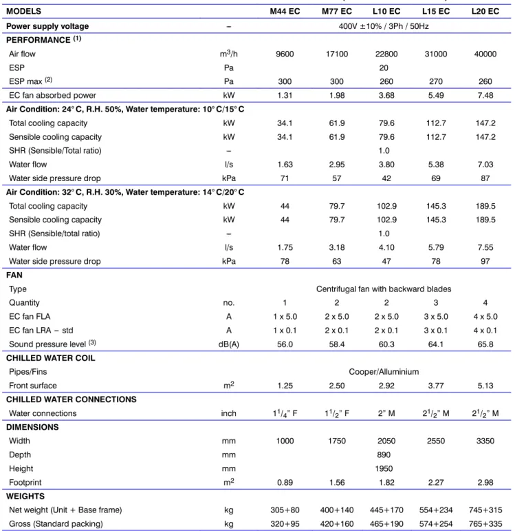
Tab. 4a --- Chilled water unit with base frame --- Liebert HPM Extended DOWN (Fans in the raised floor)
MODELS M44 EC M77 EC L10 EC L15 EC L20 EC
Power supply voltage --- 400V ±10% / 3Ph / 50Hz
PERFORMANCE(1)
Air flow m3/h 9600 17100 22800 31000 40000
ESP Pa 20
ESP max(2) Pa 300 300 260 270 260
EC fan absorbed power kW 1.31 1.98 3.68 5.49 7.48
Air Condition: 24° C, R.H. 50%, Water temperature: 10° C/15° C
Total cooling capacity kW 34.1 61.9 79.6 112.7 147.2
Sensible cooling capacity kW 34.1 61.9 79.6 112.7 147.2
SHR (Sensible/Total ratio) --- 1.0
Water flow l/s 1.63 2.95 3.80 5.38 7.03
Water side pressure drop kPa 71 57 42 69 87
Air Condition: 32° C, R.H. 30%, Water temperature: 14° C/20° C
Total cooling capacity kW 44 79.7 102.9 145.3 189.5
Sensible cooling capacity kW 44 79.7 102.9 145.3 189.5
SHR (Sensible/total ratio) --- 1.0
Water flow l/s 1.75 3.18 4.10 5.79 7.55
Water side pressure drop kPa 78 63 47 78 97
FAN
Type Centrifugal fan with backward blades
Quantity no. 1 2 2 3 4
EC fan FLA A 1 x 5.0 2 x 5.0 2 x 5.0 3 x 5.0 4 x 5.0
EC fan LRA --- std A 1 x 0.1 2 x 0.1 2 x 0.1 3 x 0.1 4 x 0.1
Sound pressure level(3) dB(A) 56.0 58.4 60.3 64.1 65.8
CHILLED WATER COIL
Pipes/Fins Cooper/Alluminium
Front surface m2 1.25 2.50 2.92 3.77 5.13
CHILLED WATER CONNECTIONS
Water connections inch 11/4” F 11/2” F 2” M 21/2” M 21/2” M
DIMENSIONS
Width mm 1000 1750 2050 2550 3350
Depth mm 890
Height mm 1950
Footprint m2 0.89 1.56 1.82 2.27 2.98
WEIGHTS
Net weight (Unit + Base frame) kg 305+80 400+140 445+170 554+234 745+315
Gross (Standard packing) kg 320+95 420+160 465+190 574+254 765+335
(1) AT THE FOLLOWING STANDARD CONDITIONS: ambient conditions 24° C db; 50% R.H.(17° C wb). The air flow of the units refers to the standard configuration with G4 class filter.
Note:Cooling capacities are gross. To obtain the net cooling capaicities the fan heat load must be substracted.
(2)Max. external static pressure for the indicated air flow.
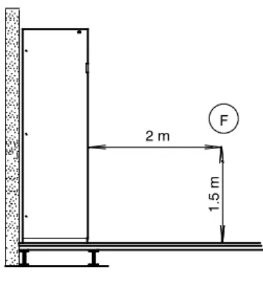
(3)Measured at 1,5 m height and 2 m front distance, in free field, at standard operating conditionswith working fan(s).
Technical Data
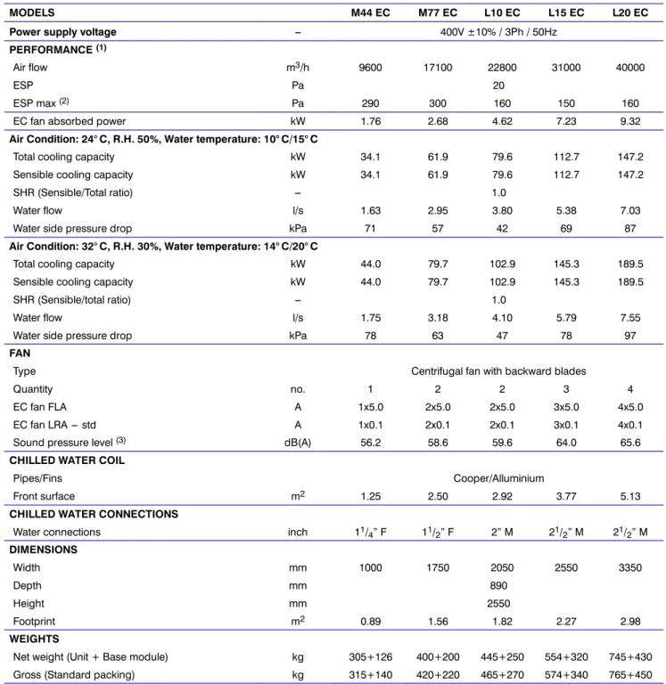
Tab. 4b --- Chilled water unit with base module --- Liebert HPM Extended UP (Fans above the raised floor)
MODELS M44 EC M77 EC L10 EC L15 EC L20 EC
Power supply voltage --- 400V ±10% / 3Ph / 50Hz
PERFORMANCE(1)
Air flow m3/h 9600 17100 22800 31000 40000
ESP Pa 20
ESP max(2) Pa 290 300 160 150 160
EC fan absorbed power kW 1.76 2.68 4.62 7.23 9.32
Air Condition: 24° C, R.H. 50%, Water temperature: 10° C/15° C
Total cooling capacity kW 34.1 61.9 79.6 112.7 147.2
Sensible cooling capacity kW 34.1 61.9 79.6 112.7 147.2
SHR (Sensible/Total ratio) --- 1.0
Water flow l/s 1.63 2.95 3.80 5.38 7.03
Water side pressure drop kPa 71 57 42 69 87
Air Condition: 32° C, R.H. 30%, Water temperature: 14° C/20° C
Total cooling capacity kW 44.0 79.7 102.9 145.3 189.5
Sensible cooling capacity kW 44.0 79.7 102.9 145.3 189.5
SHR (Sensible/total ratio) --- 1.0
Water flow l/s 1.75 3.18 4.10 5.79 7.55
Water side pressure drop kPa 78 63 47 78 97
FAN
Type Centrifugal fan with backward blades
Quantity no. 1 2 2 3 4
EC fan FLA A 1x5.0 2x5.0 2x5.0 3x5.0 4x5.0
EC fan LRA --- std A 1x0.1 2x0.1 2x0.1 3x0.1 4x0.1
Sound pressure level(3) dB(A) 56.2 58.6 59.6 64.0 65.6
CHILLED WATER COIL
Pipes/Fins Cooper/Alluminium
Front surface m2 1.25 2.50 2.92 3.77 5.13
CHILLED WATER CONNECTIONS
Water connections inch 11/4” F 11/2” F 2” M 21/2” M 21/2” M
DIMENSIONS
Width mm 1000 1750 2050 2550 3350
Depth mm 890
Height mm 2550
Footprint m2 0.89 1.56 1.82 2.27 2.98
WEIGHTS
Net weight (Unit + Base module) kg 305+126 400+200 445+250 554+320 745+430
Gross (Standard packing) kg 315+140 420+220 465+270 574+340 765+450
(1) AT THE FOLLOWING STANDARD CONDITIONS: ambient conditions 24° C db; 50% R.H.(17° C wb). The air flow of the units refers to the standard configuration with G4 class filter.
Note:Cooling capacities are gross. To obtain the net cooling capaicities the fan heat load must be substracted.
(2)Max. external static pressure for the indicated air flow.
(3)Measured at 1,5 m height and 2 m front distance, in free field, at standard operating conditionswith working fan(s).
5 Air Flow Characteristics
Air Flow Characteristics
Liebert HPM Extended DOWN with fans in the raised floor
The graphs give the available and allowed external static pressure against airflow at different motor supply voltages for all the units, with G4 air filter, standard configuration.
The air conditioners of the Liebert HPM Extended EC series are supplied with fans sized for 20 Pa Available External Static Pressure (ESP).
0 50 100 150 200 250 300
3500 5000 6500 8000 9500 11000 12500
HPM M44EC ESP
9600 mc/h
m3/h
Pa 7V 8V 9V 10V
6V
5V
4V
0 50 100 150 200 250 300
7500 10000 12500 15000 17500 20000 22500 25000 27500
HPM M77EC ESP
17100 mc/h
m3/h
Pa 7V 8V 9V 10V
6V
5V
4V
0 50 100 150 200 250 300
8000 10500 13000 15500 18000 20500 23000 25500 28000
HPM L10EC ESP
22800 mc/h
m3/h Pa
10V 9V
7V 8V
6V
5V
4V
0 50 100 150 200 250 300
11500 16500 21500 26500 31500 36500
HPM L15EC ESP
31000 mc/h
m3/h
Pa 7V 8V 9V 10V
6V
5V
4V
0 50 100 150 200 250 300
14500 19500 24500 29500 34500 39500 44500 49500
HPM L20EC ESP
40000 mc/h
m3/h Pa
10V 8V 9V
7V
6V
5V
4V
Air Flow Characteristics
Liebert HPM Extended UP with fans above the raised floor
The graphs give the available and allowed external static pressure against airflow at different motor supply voltages for all the units, with G4 air filter, standard configuration.
The air conditioners of the Liebert HPM Extended EC series are supplied with fans sized for 20 Pa Available External Static Pressure (ESP).
0 50 100 150 200 250 300
3000 4500 6000 7500 9000 10500 12000
HPM M44EC ESP
9600 mc/h
m3/h
Pa 7V 8V 9V 10V
6V
5V
4V
0 50 100 150 200 250 300
6500 9000 11500 14000 16500 19000 21500 24000
HPM M77EC ESP
17100 mc/h
m3/h
Pa 7V 8V 9V 10V
6V
5V
4V
0 50 100 150 200 250 300
7500 10000 12500 15000 17500 20000 22500 25000
HPM L10EC ESP
22800 mc/h
m3/h
Pa 7V 8V 9V 10V
6V
5V
4V
0 50 100 150 200 250 300
10000 15000 20000 25000 30000 35000
HPM L15EC ESP
31000 mc/h
m3/h
Pa 7V 8V 9V 10V
6V
5V
4V
0 50 100 150 200 250 300
13500 18500 23500 28500 33500 38500 43500
HPM L20EC ESP
40000 mc/h
m3/h
Pa 7V 8V 9V 10V
6V
5V
4V
2 m F
1.5m
6 Sound Pressure Level
Sound Pressure Level
Liebert HPM Extended units have been designed with particular care for sound and vibration problems. The complete mechanical insulation of the ventilating section, combined with the special study of the aeraulic circuit as a consequence of accurate researches made in our thermodynamical laboratories and the oversizing of the components crossed by air offer the highest ventilation efficiency with the lowest sound emission.
Sound emission spectra
All tests are performed in our laboratories under the described conditions. The instrument is placed in (F) point, at 1.5 m from the ground in front of the machine at 2 m distance. Test conditions: Under unit with underflow air discharge and 20 Pa available external static pressure.
Standard air flow with clean G4 filters. Ambient temperature 24°C and relative humidity 50%. Condensing temperature 45°C.
The noise levels refer to free field conditions.
Sound emission spectra
The following tables show sound levels for every octave band frequency.
Tab. 6a --- Liebert HPM Extended DOWN (Fans in the raised floor)
MODEL Mode Level Octave band frequency (Hz) Sound Level
[dB(A)]
31.5 63 125 250 500 1000 2000 4000 8000
M44 EC (1) SPL 61.6 61.1 66.5 57.5 52.4 48.3 45.4 40.2 31.2 56.0
(4) PWL 70.7 70.7 78.6 82.0 74.3 72.5 70.4 65.7 62.0 78.7
M77 EC (1) SPL 58.6 57.6 57.5 61.1 53.2 53.1 50.8 43.0 38.5 58.4
(4) PWL 70.6 70.6 78.5 81.9 74.2 72.4 70.3 65.6 61.9 78.6
L10 EC (1) SPL 70.0 63.0 63.6 66.3 55.8 48.5 50.5 40.3 32.6 60.3
(4) PWL 82.0 82.0 91.9 89.8 82.0 77.4 76.6 67.6 59.8 85.7
L15 EC (1) SPL 76.1 76.2 74.8 65.5 60.8 55.5 52.0 48.2 33.4 64.1
(4) PWL 84.6 84.6 94.5 92.4 84.6 80.0 79.2 70.2 62.4 88.3
L20 EC (1) SPL 74.3 74.3 76.1 66.9 62.9 57.4 55.0 50.5 40.6 65.8
(4) PWL 86.8 86.8 96.7 94.6 86.8 82.2 81.4 72.4 64.6 90.5
Tab. 6b --- Liebert HPM Extended UP (Fans above the raised floor)
MODEL Mode Level Octave band frequency (Hz) Sound Level
[dB(A)]
31.5 63 125 250 500 1000 2000 4000 8000
M44 EC (1) SPL 54.6 54.6 53.2 57.1 53.2 50.2 49.2 41.9 39.6 56.2
(4) PWL 70.9 70.9 78.8 82.2 74.5 72.7 70.6 65.9 62.2 78.9
M77 EC (1) SPL 58.8 57.8 57.7 61.3 53.4 53.3 51.0 43.2 38.7 58.6
(4) PWL 70.8 70.8 78.7 82.1 74.4 72.6 70.5 65.8 62.1 78.8
L10 EC (1) SPL 69.3 62.3 62.9 65.6 55.1 47.8 49.8 39.6 31.9 59.6
(4) PWL 81.3 81.3 91.2 89.1 81.3 76.7 75.9 66.9 59.1 85.0
L15 EC (1) SPL 73.7 66.7 67.3 70.0 59.5 52.2 54.2 44.0 36.3 64.0
(4) PWL 85.7 85.7 95.6 93.5 85.7 81.1 80.3 71.3 63.5 89.4
L20 EC (1) SPL 78.1 77.9 73.8 68.4 62.4 57.1 55.1 49.7 39.8 65.6
(4) PWL 88.5 88.5 98.4 96.3 88.5 83.9 83.1 74.1 66.3 92.2
1row 2rows
2 m F
1.5m
45°
1 m D
Sound Pressure Level
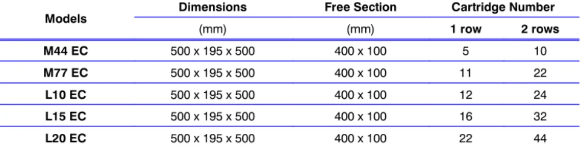
Silencing cartridges (option)
These are special cartridges made of self---extinguishing material with a high noise attenuation capacity. They are guaranteed against disintegration and release of particles do to friction of the air.
It is possible to installoneortworows of cartridges in the supply hood by inserting them through the top: one single row for²600 mm height hood, two rows for a hood height 1200 mm.
Despite a small additional pressure drop, these cartridges provide a remarkable sound power level reduction (see tab. 7d).
Tab. 6c --- Features of silencing cartridges
Models Dimensions Free Section Cartridge Number
(mm) (mm) 1 row 2 rows
M44 EC 500 x 195 x 500 400 x 100 5 10
M77 EC 500 x 195 x 500 400 x 100 11 22
L10 EC 500 x 195 x 500 400 x 100 12 24
L15 EC 500 x 195 x 500 400 x 100 16 32
L20 EC 500 x 195 x 500 400 x 100 22 44
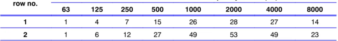
Tab. 6d --- Attenuation in dB
row no. Attenuation in dB at different frequency values (Hz)
63 125 250 500 1000 2000 4000 8000
1 1 4 7 15 26 28 27 14
2 1 6 12 27 49 53 49 23
Tab. 6e --- Pressure drops
row no. Pressure drops (Pa) for each module at different air flows (m3/s)
0.2 0.3 0.4 0.5 0.6
1 1 2 4 7 9
2 3 6 11 18 26
Approximate variations of sound pressure level
Variations compared to values measured without noise reduction duct.
PositionF: 2 meters from the front, 1.5 meter from the ground.
PositionD: 1 meter from the front, 45° from the top.
Unit Configuration Plenum Height Cartridge Rows Number
Position
F D
Under 600 mm 1 ---4.0 dB ---7.0 dB
1200 mm 2 ---5.0 dB ---8.0 dB
7 Technical Specifications
Technical Specifications
Fan (room unit)
Innovative application of single inlet centrifugal fans incorporating an impeller with curved blades corrosion resistant made of aluminium with new design to get increased performances and sound radiation free of tonal noise.
High efficiency.
The motor is three---phase with IP54 protection;
provided with internal thermal protection.
The fan wheel is statically and dynamically balanced; the bearings are self---lubricating.
Other information: seeChap. 1.
Air filters
(see Chap. 8)Coils
CW Chilled water/room air High front surface.
Made of copper pipes and aluminium fins.
Fins treated with hydrofile styrol acrylic paints to withstand corrosive atmospheres.
Low pressure drop.
High SHR (Sensible Heat Ratio).
Frame and panels
The sheet steel structure, painted with epoxy---polyester powders, is assembled by stainless steel rivets; the paneling system ensures higher stiffness; there will also be some pluggings for guaranteeing both safety and high acoustic absorption.
The frontal panel is assembled on hinges to make the access easier; this can be opened by the fast closing lock.
The rear and side panels are screwed to the supports. The rear panel is screwed directly to the frame.
The air returns from the machine top in machines with underfloor air delivery.
The panels are lined with thermoacoustic insulating material --- class 0 (ISO 11822).
Electric board
The electric board is housed in the front part in a space insulated against the air flow and protected by a plastic crankcase, so as to avoid tampering by non---authorized personnel and to protect the electric board parts supplied with a voltage higher than 24 V.
The electric board complies with the norm 204---1 IEC.
The air conditioners have been provided for operating at 400 V∼/3/50 Hz+N+G (as alternative execution, the version with 230∼V/3/50Hz + G can be supplied in the majority of cases).
Magnetothermal switches are supplied as protection of every electric component. A single---phase transformer has been provided for supplying power to the secondary circuit at 24 V.
A main switch with door---locking handle is installed in series on the safety crankcase to prevent it from being removed when the switch is in the operating position.
There will be an automatic start---up after a possible stop due to power supply lack.
Additional terminals for remote start---up and carry of some operating conditions (fans and compressors) or connection of additional devices (Liquistat, Firestat, Smokestat, clogged filters) are set in series on the terminal board of the electric board. On the terminal board there is also a clean contact for the remote signalling of the general alarm.
Technical Specifications
Control system
Very simple user interface.
Immediately intelligible utilization of the control unit system with LCD.
Net connectivity of several units.
Possible utilization of the iCom CDL with graphicdisplay.
8 Filter section
Filter section
Standard filters
Removable filters installed inside the unit before of fan and heat exchanger.
Filtration with G2, G4 and F5 (CN EN779 --- respectively corresponding to EU2, EU4 and EU5 accoding to Eurovent EU2/4/5).
The folded structure of the filters gives high filtration efficiency and low pressure drop. The filter media used consists of synthetic fibre cells. The frame is made of cardboard. The additional pressure drop in comparison with G4 sdt filters are indicated in Tab. 8c.
High efficiency filters
Optional high efficiency filters, filtration class F6, F7 and F9 in accordance with the CEN EN 779 standard, are made of fibreglass filter media. The filters are placed in ”V” sections with a solid external frame in polypropylene, and can withstand remarkable pressure and flow variations. These filters will be installed within an additional duct on the unit top.
Filter holding duct
If 290 mm high filters are needed, a metal hood must be supplied to support them, installed on the top of the unit and with the same colour. For dimensions see Fig. 11.d.
Clogged filter alarm
A differential static pressure gauge after anf before the filter gives a signal when the filter is dirty.
Fresh air kit
The fresh air kit, optional, has a G3 class filter installed on the intake side of the fan and is connected to the HPM unit with a 100 mm diameter plastic duct.
As the fresh air intake is positioned close to the fan suction, it will easily mix with the recirculation air.
Air Filters general information
Recently new test methods and configuration systems have been developed for all type of filters.
In Europe, CEN is working to establish common standards, in the United States ASHRAE Standards has been in use since 1968, and replaced by ANSI/ASHRAE 52.1---1992. So, in order to have a reference about different standards, see Tab. 8a and Tab 8b. There is no perfect correspondence between different standards, due to the different test methods, but the tables can be used as general guide.
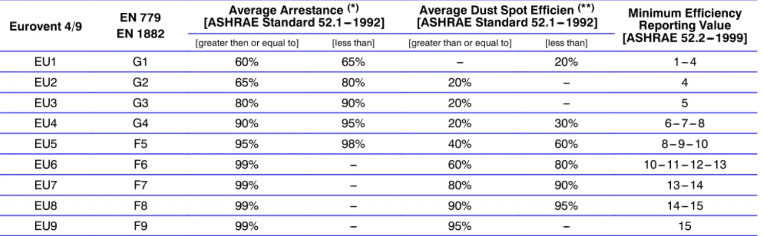
Tab. 8a --- Comparison between air filter tests Eurovent 4/9 EN 779
EN 1882
Average Arrestance(*)
[ASHRAE Standard 52.1---1992] Average Dust Spot Efficien(**)
[ASHRAE Standard 52.1---1992] Minimum Efficiency Reporting Value [ASHRAE 52.2---1999]
[greater then or equal to] [less than] [greater than or equal to] [less than]
EU1 G1 60% 65% --- 20% 1---4
EU2 G2 65% 80% 20% --- 4
EU3 G3 80% 90% 20% --- 5
EU4 G4 90% 95% 20% 30% 6---7---8
EU5 F5 95% 98% 40% 60% 8---9---10
EU6 F6 99% --- 60% 80% 10---11---12---13
EU7 F7 99% --- 80% 90% 13---14
EU8 F8 99% --- 90% 95% 14---15
EU9 F9 99% --- 95% --- 15
(*) Achieved filtering performance in accordance to gravimetric test method on a specific sample of dust.
(**) Achieved filtering performance in accordance to a light transmission test methods, with natural atmospheric dust.
Filter section
Tab. 8b --- Approximate efficiency versus particle size for typical air filters
EFFICIENCY%
PARTICLE SIZE. MICROMETRES
Curves are approximation for general guidance only. Efficiency and arrestance per ASHRAE Std 52.1 test method [From ASHRAE Handbook, HVAC Systems and Equipment].
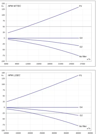
Tab. 8c --- Pressure drop with standard Filters G2, G4 and F5
-100 -75 -50 -25 0 25 50 75 100 125 150
3500 5000 6500 8000 9500 11000 12500 14000 15500
HPM M44EC
m3/h
Pa F5
G2
No filter G4
-100 -75 -50 -25 0 25 50 75 100 125 150
6000 9000 12000 15000 18000 21000 24000 27000
HPM M77EC
m3/h
Pa F5
G2
No filter G4
-100 -75 -50 -25 0 25 50 75 100 125 150
7500 12500 17500 22500 27500 32500
HPM L10EC
m3/h Pa
F5
G2
No filter G4
-100 -75 -50 -25 0 25 50 75 100 125 150
10000 15000 20000 25000 30000 35000 40000 45000
HPM L15EC
m3/h
Pa F5
G2
No filter G4
-100 -75 -50 -25 0 25 50 75 100 125 150
10000 15000 20000 25000 30000 35000 40000 45000 50000 55000 HPM L20EC
m3/h
Pa F5
G2
No filter G4
Filter section
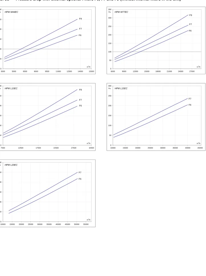
Tab. 8d --- Pressure drop with external optional Filters F6, F7 and F9 (without internal filters in the unit)
0 50 100 150 200 250 300
3500 5000 6500 8000 9500 11000 12500 14000 15500
HPM M44EC
m3/h Pa
F6 F9
F7
0 50 100 150 200 250 300 350
6000 9000 12000 15000 18000 21000 24000 27000
HPM M77EC
m3/h Pa
F6 F9
F7
0 50 100 150 200 250 300
7500 12500 17500 22500 27500 32500
HPM L10EC
m3/h Pa
F6 F9
F7
0 50 100 150 200 250 300
10000 15000 20000 25000 30000 35000 40000 45000
HPM L15EC
m3/h Pa
F6 F7
0 50 100 150 200 250 300
10000 15000 20000 25000 30000 35000 40000 45000 50000 55000 HPM L20EC
m3/h Pa
F6 F7
Fig. 9.a
9 Microprocessor Controls
Microprocessor Controls
iCOM Control
Liebert HPM models are controlled by iCOM Medium (Fig. 9.a).
The Main Board is housed in the electrical panel and it is connected to the remote display, to be installed in the container/room (connection cable is included).
D The user interface is the 3---digitback---lit display showing parameter values and relevant symbols/codes in a tree menu. It features navigation push---buttons and status leds.
D Both high and low priority alarms activate a visual indicator and buzzer.
D Input for Remote On---Off and volt---free contacts for simple remote monitoring of low and high priority alarms:
high/low room temperature, high/low refrigerant pressure, fan/control failure are available.
D LAN management: functions provided as standard include stand---by (in case of failure or overload of the unit
in operation, the second one starts automatically), automatic rotation, and cascade (division of the load among several units, through split of the proportional band).
D The self---test function automatically activates/deactivates the
main components (evaporator fan, compressor, freecooling damper, heaters, alarms) without changing the pre---set parameters, to easily start---up and commission the unit. No skilled personnel are requested (*).
D All settings are protected through a 3---Level password system(*).
D Automatic restart is provided after a power failure.
(*) The Remote display is required to activate the function.
Tab. 9a --- Technical DataiCOM Medium
Technical Data iCOM Medium
E2prom 4Mbit + 512kbit
Flash memory 32Mbit
RAM memory space 128Mbit
Microcontroller Coldfire 32Mbit
Analogue Input 3 x 0---10V,0---5V,4..20mA (selectable) + 2 PTC/NTC + 3 NTC
Digital Input 9 x opto---coupled
Analogue Output 2 x 0---10V
Digital Output 7 triacs output and 2 relay output
Time and date function buffered by LI---battery
Hirobus Lan connectors 2 RJ45 sockets (for unit in LAN, remote display)
Ethernet network connectors 1 RJ45 socket
CAN bus connectors 2 RJ12 sockets
Hironet connectors 1 RJ9 socket for RS485 (direct connection to proprietary supervision)
Microprocessor Controls
CDL Graphic Display (option)
Featuring a 24h graphic record of controlled parameters as well as the last 200 events occurred. A back---up battery keeps the data stored in the memory (graphic data record, alarms).
D Large graphic display (320 x 240 pixel)
D System Window: system operation status at a glance
D Self---explanatory Icons: they are used for the Menu---Layout of the CDL iCOM
D Online Help: Every single parameter has its own multi---page explanation (Evolution)
D Status Report of the latest 200 event---messages of the unit/system
D Four different Graphic Data Records (Evolution)
D Timer Mode (electronic timer included in the Software)
D Semi or Full Manual Mode software management including all safety devices
D 4---Level Passwords system to protect all the settings
D Ergonomic design for use also as portable device (start---up and ”flying connections” by service personnel)
D Multi---language menu with on---the---fly language selection Technical Data CDL Graphic Display
--- Microcontroller: . . . .Coldfire 32Mbit
--- Time and date function buffered by LI---battery
--- Ethernet network connectors . . . .2 RJ45 sockets (for unit in LAN, remote display)
--- CAN bus connectors . . . .2 RJ12 sockets
--- Power supply: . . . .via CAN bus or external 12Vdc supply
Alarm Board (accessory)
The Alarm Board converts Alarms (high priority) or Warnings (lower priority) from iCOM into Volt---free contacts (up to five, either normally closed or normally open). In this way, following Warnings/Alarms are separated: High or Low refrigerant pressure; High room Temperature; Low room Temperature; Fan Failure, Clogged Filter alarm (if installed).
SMM, Wireless SMS Communication (accessory)
The unit is able to send short text messages (SMS) of the its status/alarms to the display of GSM900---1800MHz mobile phones, allowing real time, cost effective maintenance.
10 Dimensional Data / Connections
Dimensional Data / Connections
Fig. 10.a --- Overall dimensions --- Service area with base frame (Liebert HPM Extended DOWN)
M44 EC
M77 EC L10 EC
L15 EC
L20 EC
1950B B B
B B
1950 1950 1950
1950
from600to1000 from600to1000
from600to1000 from600to1000 from600to1000
Models
AVAILABLE PLENUM HEIGHTS: B (mm)
Plenum simple Plenum for
silencing cartridges Plenum for high efficiency filters M44 EC 500 / 600 / 700 / 800 / 900
1000 / 1100 / 1200 600 / 900 / 1200 500 / 600 / 700 / 800 / 900 M77 EC
L10 EC 500 / 600 / 700 / 800 / 900
1000 / 1100 / 1200 600 / 900 / 1200 600 / 700 / 800 / 900 L15 EC
L20 EC 600 / 900 600 / 900 600 / 900
Dimensional Data / Connections
Fig. 10.b --- Overall dimensions --- Service area with base module (Liebert HPM Extended UP)
L20 EC
B1950600
M44 EC
M77 EC L10 EC
L15 EC
1950600B B B
B 1950600 1950600
1950600from300to1000 from300to1000 from300to1000
from300to1000 from300to1000
Models
AVAILABLE PLENUM HEIGHTS: B (mm)
Plenum simple Plenum for
silencing cartridges Plenum for high efficiency filters M44 EC 500 / 600 / 700 / 800 / 900
1000 / 1100 / 1200 600 / 900 / 1200 500 / 600 / 700 / 800 / 900 M77 EC
L10 EC 500 / 600 / 700 / 800 / 900
1000 / 1100 / 1200 600 / 900 / 1200 600 / 700 / 800 / 900 L15 EC
L20 EC 600 / 900 600 / 900 600 / 900
Dimensional Data / Connections
Tab. 10a --- Unit weights
MODELS
WEIGHTS(kg)
Unit Base frame
(Liebert HPM Extended DOWN)
Base module (Liebert HPM Extended UP)
M44 EC 305 80 126
M77 EC 400 140 200
L10 EC 445 170 250
L15 EC 554 234 320
L20 EC 745 315 430
Fig. 10.c --- Accessories and options diagram
Silencing cartridges
High efficiency filters
Horizontal input grille
Extension hood
OR
Intake and delivery hoods
Liebert HPM Extended can be equipped with intake ducts on the top for connection of the unit to a false ceiling. The air duct is manufactured to complement the design of the unit; it consists of sandwich panels lined with non---flammable insulation material of Class 0 (ISO 1182.2), density 30 kg/m3; its height ranges between 500 mm and 1200 mm.
Dimensional Data / Connections
Fig. 10.d --- Fan module installation (Hole in the floor)
WALL
Front of the unit
Base module Liebert HPM Extended UP A
B C
Base frame
Liebert HPM Extended DOWN
Front of the unit E
F
600 D
D
F
E Front of the unit
MODELS
Dimensions[mm]
A B C D
E F
with base frame with base module
M44 EC 1000
895 10 From 600
to 1000 From 300
to 1000
990
885
M77 EC 1750 1740
L10 EC 2050 2040
L15 EC 2550 2540
L20 EC 3350 3340
Dimensional Data / Connections
Packing
Fig. 10.e --- Packing of standard unit
4 5 3
2 6
1 7
8
C
The air conditioners are usually packed on a wooden pallet (1), with shockproof angle pieces in pressed cardboard (2, 3, 4, 5), panels in cardboard (6, 7) and flexible polythene film (8).
Base frames are packed on a wooden structure (9).
Fig. 10.f --- Packing of base frame and base module
B
C C
B
A A
7
7 6
6
9
9 9
1
1 5
4
Base module Liebert HPM Extended UP Base frame
Liebert HPM Extended DOWN
Tab. 10b --- Packing dimension
HPMunit
Dimensions
(mm) Base
frame
Dimensions
(mm) Base
module
Dimensions (mm)
A B C A B C A B C
M44 EC
930 1080 2110
M44 EC
1060 1080
724
M44 EC
960 1080
776
M77 EC 1830 M77 EC 1930 M77 EC 1830
L10 EC 970
2130 L10 EC 2230 L10 EC 2130
L15 EC 2630 L15 EC 2730 L15 EC 2630
L20 EC 3430 2310 L20 EC 3530 L20 EC 3430
Special packing(options)
Special packing for sea transport, consisting of a wooden box or crate, can be supplied on request.