The unit is supplied with rubber mounting pads and spring vibration isolators are not required. If the touch screen stops working, the unit and compressor controls will continue to run the chiller smoothly. The unit controller takes care of those functions common to the entire chiller (pumps, cooling tower, valves, etc.) and is the interface point for connecting the BAS and other control inputs to the chiller and outputs, such as the operation of the electronic expansion valve.
The Magnitude chiller control system consists of two main components: the unit control panel, as shown on the right, and the operator interface panel as shown on the left edge of the unit shown on the cover. The control panel features a USB port for downloading the unit's fault history, key parameter trends, and the unit's operating manual stored in the microprocessor. The photo on the right shows the unit control panel with the two compressor controllers below and the unit controller mounted above them.
The unit controller is responsible for functions involving the entire unit (for example, controlling the electronic expansion valve) and is the interface point for devices and signals outside the unit. task is to operate and regulate the compressors. If the pressure continues to rise, the unit will shut down at the set cut-out pressure.
MicroTech Controller Increases Chiller Operating Economy
Versatile Communications Capabilities Give You Even More Control
Building Automation Systems All MicroTech II controllers are capable of
Output Capacity Limit R Cond EWT R Evaporative Water Pump Status R Capacity Limit Setpoint W Conditioning Flow Switch Status R Pump Selection W. Refrigerant Limited R Conditioning Pump Hours R Liquid Line Refrigerant Pressure R Local/Remote R Refrigerant Pressure of conditioning R refrigerant in the liquid line Temp R Cooling mode Outlet R Cond Sat. Coolant Temperature R Maximum Shipping Time W Cooling Mode Setpoint W Water Pump Status Cond R Minimum Shipping Time R.
Chiller Status R Flow Switch Status Switch R Cooling Set Point W Compressor Discharge Temp R Evaporator LWT For Unit R Current Alarm R Compressor Percentage RLA R Evaporator LWT For Compressor R Defaults W Compressor Run Hours R Evaporator Pump Run Hours R Active Set Point R Select Compressor W Evap Refrigerant Pressure R Actual Capacity R Compressor Start R Verd sat. Refrigerant Temp R Compressor Suction Line Temp R Notes: Available data depends on options selected.
Network Protocol Options
Unit Design Features
Variable Frequency Drive
HFC-134a
Heat Exchangers
Pumpdown
Electronic Expansion Valve
Flow Switch
Factory Performance Test
Optional Certified Test
Optional Witness Test
McQuay Factory Service Startup
Part Load Efficiency
Compliance with ASHRAE Std. 90.1 With the Magnitude chiller capacity range of 145
ARI Certification
Note that the vast majority of hours are at the operating range where twin compressor coolers excel. DTFL = Chilled Water Delta-T at Full Load This formula results in a ±5% tolerance on tonnes and kW/ton at the 100% load point and ARI conditions.
Chiller Identification
Sound Data
Eight-Octave Band
One-Third Octave Band
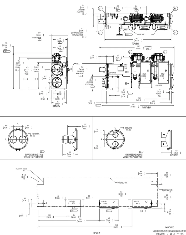
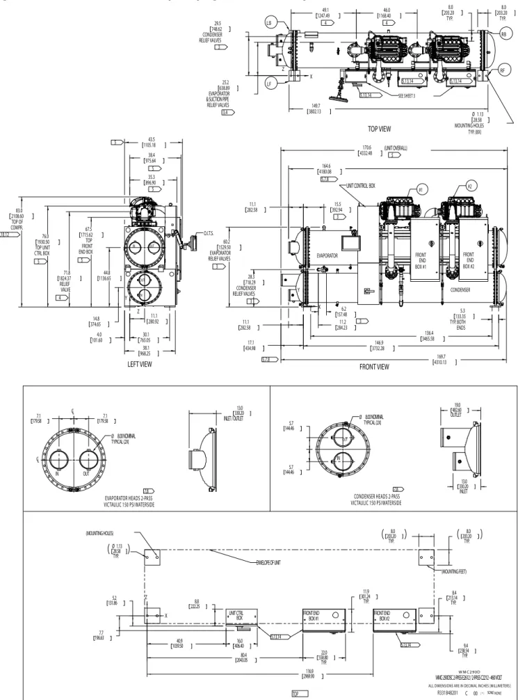
Dimensions
Marine Water Box Dimensions with Victaulic or Flanged Connections
Drawing Notes NOTES
Physical Data and Weights
Mounting/Lifting Weights
Physical Data
Evaporator
Condenser
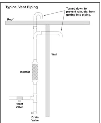
Relief Valves
Vessel Relief Valves
Relief Pipe Sizing (ASHRAE Method) Relief valve pipe sizing is based on the discharge
Electrical Data
WMC 145S (Single Compressor)
WMC 145D & 150D (Dual Compressors)
Multi-point Connection, Standard Table 18, WMC 145D, 150D Electrical Data
Single-point Connection, Optional Table 19, WMC 145D, 150D Electrical Data
Single Point and Multi-point Connection
WMC 250D & 290D (Dual Compressors)
WMC 400D (Dual Compressors)
Wiring must be wired in accordance with the NEC and the connection must be made with copper wire and copper plugs only. Voltage unbalance must not exceed 2% with resulting current unbalance 6 to 10 times voltage unbalance per NEMA MG-1, 1998. Customer supplied 24 or 120 VAC supply for alarm relay coil may be connected between terminal UTB1 84 for power and 81 neutral on the control panel.
If field-supplied flow switches are used in addition to the factory-installed flow switches, they must be wired as shown and must be suitable for 24 V and low current use. 115 VAC 20 amp supply for optional evaporator and condenser water pump control power and tower fans are supplied to unit control terminals (UTB1) 85 power / 86 neutral, PE equipment ground. Optional Chilled Water Pump Relay (ep1 and 2) 115 VAC, 25 VA maximum coil rating can be wired as shown.
A customer supplied 115 VAC 25 VA maximum coil rating, condenser water pump relay (CP1 & 2) should be wired as shown. Optional customer supplied 115 VAC 25 VA maximum cooling tower fan relays (C1 - C2 standard, C3-C4 optional) can be wired as shown. This option runs the cooling tower fans to maintain unit head pressure.
An external 4-20mA chilled water reset signal can be connected to terminals 71 and 51 on the unit controller; the load limit is connected to terminals 71 and 58 on the unit controller.
Power Factor
VFD Line Harmonics
Application
Considerations
Location
Optimum Water
Temperatures and Flow
Higher leaving chilled water temperatures
Evaporator temperature drop The industry standard has been a ten-degree
Condenser water temperature rise The industry standard of 3 gpm/ton or about a 9.5-
Chilled Water Temperature
Piping
Condenser Water Temperature
To achieve lower than 55°F (12.8°C) entering condenser water temperature with a tower selected to produce 85°F (29.4°C) water temperature at design ambient air temperatures, cooling tower fans must continue to operate at 100% capacity at low wet bulb temperatures. Since coolers are chosen for lower kW per ton, the cooling tower fan motor power becomes a higher percentage of the peak chiller power. On the other hand, the low condenser water temperatures can be easy and economical to achieve in mild climates with low wet bulb temperatures.
Even with tower fan control, some form of water flow control, such as tower bypass, must be used. The bypass valve and piping are inside and thus warmer, allowing the warmer water to be immediately available to the condenser.
Pumps
Variable Speed Chilled Water Pumping
Figure 21, Tower Bypass, Cold Weather Operation (Indoor Bypass). 0.91 m/s), laminar flow occurs, which reduces heat transfer and causes malfunction. In other words, there is no chiller energy consumption and considerable pumping energy can be saved. Although variable rate pumping can be implemented in a capacitor loop, it is usually unwise.
However, reducing the water flow in the condenser increases the condensing pressure of the chiller, thereby increasing the lift that the compressor must overcome, which in turn increases the energy consumption of the compressor. As a result, the energy saving of the pump can be lost because the working power of the cooling device is significantly increased. Low condenser flow rates and pipe velocities can cause premature pipe fouling and consequently increased compressor energy consumption.
Vibration Mounting
System Water Volume
System Pumps
System analysis
Operating Limits
Retrofit Knockdown
The compressor(s), control panel, and compressor power panel(s) are removed at the
The unit ships fully assembled and charged with refrigerant and is ready for field
Pressure Drop Curves
WMC Cond - Water Side Pressure Drop (3 pass)
Options and Accessories
Vessels
Controls
Unit
Electrical
Refrigerant Recovery Units
Model RRU Refrigerant Recovery Units
Size and Specifications
Refrigerant Compatibility
Standard Equipment
Model RRU134
MODEL RRU570
Model PRU Packaged Recovery Units
Accessories
Refrigerant Monitors
Specifications
SECTION 15XXX
MAGNETIC BEARING CENTRIFUGAL CHILLERS
GENERAL 1.1 SUMMARY
- REFERENCES
- SUBMITTALS
- DELIVERY AND HANDLING
- WARRANTY
- MAINTENANCE
PRODUCTS
- UNIT DESCRIPTION
- DESIGN REQUIREMENTS
- CHILLER COMPONENTS A. Compressors
- OPTIONAL ITEMS
- INSTALLATION
- START-UP
Each unit must be equipped with two (one on the WMC 145 model) multi-stage, oil-free, magnetic bearing, hermetic. Each chiller must be factory tested on an AHRI certified test stand with water at operating conditions (excluding glycol). The refrigerant charge must be adjusted for optimum performance and recorded on the unit's nameplate.
Note: Refrigerants must be charged with a refrigerant such as HFC-134a, which is not subject to phase-out by the Montreal Protocol and the U. The compressor drive train must be capable of a controlled and safe stop in the event of a surge failure. The evaporator and condenser shall be of the shell and tube type, designed, constructed, tested and stamped in accordance with the requirements of the ASME Code, Section VIII.
Water sides must be designed for a minimum of 150 psig OR 300 psig or as specified elsewhere. Spring-loaded, resettable relief valves must be provided in accordance with ASHRAE-15 Safety Code. The motor shall be liquid cooled with internal thermal overload protection devices built into the windings of each phase.
The chiller shall be equipped with a variable frequency drive (VFD) to automatically regulate each compressor speed in response to refrigeration load and compressor pressure lift. An operation and maintenance manual specific to the device must be viewable on the screen and downloadable. System specific chiller architecture software must be used to display the chiller, pipes, pumps and cooling tower.
For chillers communicating over the LONMARK network, a suitable LONMARK External Interface (XIF) file must be provided with chiller submission information. All communication with the chiller controller as specified in the list of points must be through standard BACnet facilities. The power connection must be single point to the factory installed disconnect switch OR multi point to each compressor power board.