Ceiling Concealed Split Systems
MCC / M5CC 010C/CR MCC / M5CC 015C/CR MCC / M5CC 020C/CR MCC / M5CC 025C/CR MCC / M5CC 028C/CR MCC 030C/CR
MCC / M5CC 038C/CR MCC 040C/CR
MCC / M5CC 050C/CR
MCC / M5CC 060C/CR
Models:
Nomenclature ...1
- Product Line Up Features ...8
Application Information ...9
- Operating Range - Refrigerant Circuit Diagram - Chiller Panel Controller - Precautions and Installation Sound Data ...27
Selection Process ...34
- Fan Performance Charts Engineering and Physical Data ...52
- Specifications Performance Data ...123
Dimensional Data ...166
Electrical Data ...171
Wiring Diagrams ...185
Servicing and Maintenance ...212
Troubleshooting ...214
Exploded View and Part List ...219
This manual supercedes MCC - 2007
“McQuay” is a registered trademark of McQuay International. All rights reserved.
2007 McQuay International. All rights reserved throughout the world.
Bulletin illustrations cover the general appearance of McQuay International products at the time of publication.
We reserve the right to make change in design and construction at any time without notice.
Note: Installation and maintenance are to be performed only by qualified personnel who are familiar with local codes and regulations, and experienced with this type of equipment.
Caution: Sharp edges and coil surfaces are a potential injury hazard. Avoid contact with them.
Warning: Moving machinery and electrical power hazards. May cause severe personal injury or
death. Disconnect and lock off power before servicing equipment.
Indoor
A A
F A -
Model Type
R : Heatpump Omitted if Cooling Only
Series C : C Series
Capacity 010 : 10,000 Btu/h
Model Name
CC : Ceiling Concealed
Refrigerant 5 : R410A Omitted if R22
Brand Electrical Characteristic
F : For Flare Type of Connection
Product Specification Variation AA : Revision
A : 220 – 240V/1Ph/50Hz K : 208 – 230V/1Ph/60Hz
CC 010 C R
5 M
M : McQuay
O A P
C A -
Model Type R : Heatpump Omitted if Cooling Only Series
C : C series Capacity
Model Name
LC : Single Split Condensing Unit
Refrigerant 5 : R410A
Omitted if R22 Model Brand
Electrical
A : 220-240V/1Ph/50Hz Market Region P : Matsushita Rotary M : Mitsubishi Rotary Compressor
Specifications Variation O : Standard Unit B : with Contactor G : Low Ambient Unit H : High Ambient Unit A : First issue
C : Export with CE marking E : Export without marking U : ETL spec
LC 010 C R
5 M
T : Toshiba Rotary I : Gold Fins L : Long Piping Unit S : With H/L Pressure Switch X : Oxygen Unit
010 : 10,000 Bth/h
M : McQuay
Control Marking Refrigerant Control
L2 08A SLM Netware III CE Mark W/out Cap.Tube
010C AFBA X X X X X X
015C AFBA X X X X X X
020C AFBA X X X X X X
025C AFBA X X X X X X
028C AFBA X X X X X X
038C AFAA X X X X X X
050C AFAA X X X X X X
060C AFAA X X X X X X
010CR AFBA X X X X X X
015CR AFBA X X X X X X
020CR AFBA X X X X X X
025CR AFBA X X X X X X
028CR AFBA X X X X X X
038CR AFAA X X X X X X
050CR AFAA X X X X X X
060CR AFAA X X X X X X
Built in Filter Rail
CLASSIFICATION
Cooling ModelHeatpmup Model
M5CC
Handset With Air Filter With EPS Drain Pan
NONMENCLATURE
Grille
Cap. Tube TXV Gold Fin High Ambient Kit Low Ambient Kit Contactor High Pressure Switch Low Pressure Switch Nantong Press. SW Phase Sequencer Drain Elbow Copeland Scroll Comp. Rotary CE Marking ETL
ACPOB X X X
ACPIB X X X X
ACPIC X X X X
ACPOC X X X
ACPIC X X X X
ACPOC X X X
FCPOC X X X X X
ACPIC X X X X
ACPOC X X X
FCPOC X X X X X
ACPOA X X X
ACPIA X X X X
FCPOA X X X X X
ACCOB X X X X X X
ACCGB X X X X X X X
FCCOB X X X X X X X X
FCCGB X X X X X X X X X
ACCOB X X X X X X
FCCOB X X X X X X X X
FCCGB X X X X X X X X X
ACCGB X X X X X X X
FCCOB X X X X X X X
FCCGB X X X X X X X X
FCCOB X X X X X X X
FCCGB X X X X X X X X
ACPOB X X X X
ACPIB X X X X X
ACPOC X X X X
ACPIC X X X X
ACPIC X X X X X
ACPOC X X X X
FCPOC X X X X X X
ACPIC X X X X X
ACPOC X X X X
FCPOC X X X X X X
ACPOA X X X X
ACPIA X X X X X
FCPOA X X X X X X
ACCOB X X X X X X X
ACCGB X X X X X X X X
FCCOB X X X X X X X X X
FCCGB X X X X X X X X X
ACCOB X X X X X X X
ACCGB X X X X X X X X
FCCOB X X X X X X X X
FCCGB X X X X X X X X X
FCCOB X X X X X X X X
FCCGB X X X X X X X X X
FCCOB X X X X X X X X
FCCGB X X X X X X X X X
061CR
Cooling ModelHeat Pump Model
015C
061C 040C
015CR 020C
025C
010CR
Classification
Marking
Refrigerant Ctrl + Fin Special Compressor
Safety Devices
050CR 035CR 050C
020CR
025CR
028CR
040CR 028C
035C
Nomenclature
010C M5LC
Space Saving, Elegance and Prestige
The unit is installed above the ceiling with only the supply and return air grille exposed to view. This ceiling concealed type of design has made it an “Evergreen” model without sacrificing the precious floor space.
The air-conditioned space will appear as elegant and prestigious as centralized air-conditioned area but with only a fraction of the cost. This model is ideal for small offices, hotel rooms, hospitals and restaurant applications.
Double Proctection Drainage System
High humidity inside the ceiling area is always the main cause of water leaking. By introducing “Built In” double drain pans solution, i.e. primary drain pan and secondary drain pan, water leaking will not be a problem anymore. The high quality Polystyrene (PS) primary drain pan come with a layer of thermal forming High Impact Polystyrene (HIPS) coating.
The primary drain pan is specially designed, with mould in gradient, for better condensate water drainage.
Furthermore, the drain pan is made of PS, which is a very good insulation material to prevent sweating. The secondary drain pan will act as a drip pan to block any water that might be dripped down thus offering an additional protection to the ceiling. In such a case, additional drain pan will not be necessary during installation which means more cost saving. A drain socket is supplied to connect both drain pans to the drainage pipe.
Easy and Flexible Installation
The physical height of the unit is only 261mm / 378mm, it is therefore offering greatest flexibility in selecting installation location.
With its special designed installation accessories, the installation job become easy and better air distribution can be achieved without extra spending on duct works.
Easy Maintenance
The simple design concept has a friendly maintenance and servicing in mind. Just loosening a few screws, remove secondary drain pan and drain guide, you can access to all the internal parts from the bottom of the unit. No water will splash down when removing the secondary drain pan makes the servicing work never easier before.
Medium Static Pressure with a Low Noise Level
This new series has a static pressure between 0 to 15 mmAq depend on duct work installation. The casing is well
insulated internally to reduce the noise level.
Ensure the operating temperature is in allowable range.
Cooling only
Heat pump
Note :
Standard operating range.
With High ambient unit. (Optional item)
Please refer to local dealer for unit of this specification.
With Low ambient kit. (Optional item)
Please refer to local dealer for unit of this specification.
Indoor temp. (°CDB)
Cooling
Outdoor temp. (°CDB)
Indoor temp. (°CWB)
Outdoor temp. (°CDB)
Indoor temp. (°CWB)
Heating
Outdoor temp. (°CWB)
-9
15 21
6
27 -5
19 35
15 46
24 52
Standard point High ambient
unit
Low ambient kit
18
-5 19 35
15 46
24
52 High ambient
unit
Low ambient kit Standard
point
Standard point
! Caution :
The use of your air conditioner
outside the range of working
temperature and humidity can
result in serious failure .
Model: MCC 010 / 015C – MLC 010 / 015C M5CC 010 / 015C – M5LC 010 /015C MCC 020C – MLC 018 / 020C M5CC 020C – M5LC 020C
M5CC 025C – M5LC 025C
Model : MCC 025C – MLC 025C
M5CC 028C – M5LC 028C
Model : MCC 028C – MLC 030C MCC 050C – MLC 050C MCC 060C – MLC 061C
MCC 038 / 040C – MLC 035 / 040C
Model : MCC / M5CC 015CR – MLC / M5LC 015CR
M5CC 025CR - M5LC 025CR
Model : M5CC 028CR – M5LC 028CR
Model : MCC 060CR – MLC 061CR
1. “ON/OFF” switch 6. “Sleep mode”
• Press to start the air conditioner unit. • Press button to activate the sleep function
• Press again to stop the unit. This function can only be activated under “cool” or heating mode operation. When it is 2. Temperature setting activated under “cool” mode operation, the
• Set the desired room temperature. set temperature will increase 0.5 °C after 30
• Press button to increase or decrease the minutes, 1 °C after 1 hour and 2°C after 2 hours set temperature. Setting range are between If it is activated under “HEAT” mode operation, 16 ° C to 30 ° C (60 ° F to 80 ° F). the set temperature will be decreased 0.5 °C
after 30 minutes, 1 °C after 1 hour and 2°C after
3. Operation Modes 2 hours.
• Press the “mode” button for select the type
of operating mode. 7. Air Swing
- Cooling Only : • Press button to activate the automatic air
COOL, DRY, FAN swing function.
- Heat Pump :
AUTO, COOL, DRY, HEAT, FAN 8. Sensor
(AUTO mode is represented by both • Infra red sensor to receive signals from COOL and HEAT LED light on) wireless controller.
4. Fan Speed selection. 9. LED Display
• Press the button until the desired fan speed • To display the set temperature (in °C) and
is achieved. timer delay setting (in hours).
5. Timer. 10. Transmission source
• Press the set button to select the switch • To transmit signals to the air conditioner.
timer of the air conditioner unit (the setting range is between 1 to 10 hours).
COOL DRY HEAT MED
HIGH AUTO TEMP MODE
SENSOR
ON/OFF
SLEEP LOW
TIMER 8
2 5 9
3
6 4 1
FAN
FAN ON/OFF
TEMP
SLEEP
TIMER MODE
7
1
2
3 4
5
6 10
7
SWING SWING
FAN
SLM AC-5300 (OPTIONAL)
Phase Sequencer
The unit with Scroll Compressor can only rotate in one direction. For this reason, a protective device (phase sequencer) is fitted to prevent incorrect wiring of the electrical phases. When the three phases are not connected correctly, the phase sequencer operates, and the unit will not start. This devise is located in the control box of the outdoor unit.
The following table shows the LED indicator light for phase sequencer under normal operation and fault conditions.
LED_P (Red)
LED_R (Yellow)
LED_S (Yellow)
LED_T (Yellow)
Normal Operation On - - -
Reverse Phase Blink Blink Blink Blink S & T Phase Missing Blink - Blink Blink
T Phase Missing Blink - - Blink
S Phase Missing Blink - Blink -
R Phase Missing - - - -
Overload Blink - - -
Sensor Missing Blink On On On
Notes: 1. “-” means LED off.
2. When R phase missing, no LED or buzzer will indicate the error, but relay 71 (Common) and 81 (NO) will cut off.
3. The unit will check the discharge sensor availability only during power up.
4. All errors can only recover through manually reset.
Error Code at 7 Segment Display Operation / Faulty Indication Blink E1 Room sensor contact loose / short Blink E2 Indoor coil sensor contact loose Blink E3 Outdoor coil sensor contact loose Blink E4 Compressor overload / Indoor coil sensor short /
Outdoor coil sensor short
Blink E5 Gas leak
Blink E6 N/A
Blink Heat LED Outdoor defrost (for Heatpump only)
(1) Installation of Indoor Unit
Install the unit in such a way that the condensate water can flow out smoothly.
The diagrams below show the screws position for duct work connection.
Preliminary Survey
• Electrical supply and installation is to confirm to local authority’s (e.g. National Electrical Board) codes and regulations.
• Voltage supply fluctuation must not exceed ± 10% of rated voltage. Electricity supply lines must be independent of welding transformers which can cause high supply fluctuation.
• Ensure that the location is convenient for wiring, piping and drainage.
• The indoor unit must be installed in such that free from any obstacles in path of cool air discharge and warm air return, and must allow spreading or air throughout the room (near the centre of the room).
• Clearance must be provided for the indoor unit from the wall and obstacles as shown in the figure.
• Use the hanger supplied with the unit.
• Ensure the support is strong enough to withstand the weight of the unit.
• Use the supplied drain socket to connect the drain pipe (the drain socket is only available for 10C/
CR to 25C/CR)
Sharp edges and coil surfaces are potential injury hazard. Avoid from contact with them.
• Install the condensing (outdoor) unit in a way such that hot air distributed by the outdoor condensing unit cannot be drawn in again (as in the case of short circuit of hot discharge air). Allow sufficient space for maintenance around the unit.
• Ensure that there is no obstruction of air flow into or out of the unit. Remove obstacles which block air intake or discharge.
• The location must be well ventilated, so that the unit can draw in and distribute plenty of air thus lowering the condensing temperature.
• A place capable of bearing the weight of the outdoor unit and isolating noise and vibration.
• A place protected from direct sunlight. Otherwise use an awning for protection, if necessary.
• The location must not be susceptible to dust or oil mist.
All Model A B C D
Minimum Distance 300 mm 1000 mm 300 mm 500 mm
CAUTION : If the condensing unit is operated in an atmosphere containing oils (including machine oils), salt (coastal area), sulphide gas (near hot spring, oil refinery plant), such substances may lead to
Installation Clearance
• Outdoor units must be installed such that there is no short circuit of the hot discharge air or obstruction to
smooth air flow. Select the coolest possible place where intake air should not be hotter than the outside
temperature (max. 45˚C).
• When the pipe length becomes too long, both the capacity and reliability drop. As the number of bends increases, system piping resistance to the refrigerant flow increases, thus lowering the cooling capacity, and as the result the font compressor may become defective. Always choose the shortest path and follow the recommendation as tabulated below:
Piping Sizes (Flare connection type) Piping sizes are as follows:
Piping Connection to The Unit s
• Align the centre of the piping and tighten the flare nut sufficiently with fingers.
• Finally tighten the flare nut with torque wrench unit the wrench clicks.
• When tightening the flare nut with torque wrench, ensure the direction for tightening follows the arrow on the wrench.
R22
R410A
Pipe Size (mm/in) Torque (Nm)
6.35 (1/4) 18
9.52 (3/8) 42
12.70 (1/2) 55
15.88 (5/8) 65
19.05 (3/4) 78
Model MLC 010C/CR MLC 015C/CR MLC 018/020C/CR MLC 025C/CR
Liquid (mm/in) 6.35 / 1/4 6.35 / 1/4 6.35 / 1/4 9.52 / 3/8
Suction (mm/in) 9.52 / 3/8 12.70 / 1/2 15.88 / 5/8 15.88 / 5/8 Model MLC 028 / 030C/CR MLC 035 / 040C/CR MLC 050C/CR MLC 061C/CR
Liquid (mm/in) 9.52 / 3/8 9.52 / 3/8 9.52 / 3/8 12.70 / 1/2
Suction (mm/in) 15.88 / 5/8 19.05 / 3/4 19.05 / 3/4 19.05 / 3/4
Model M5LC 010C/CR M5LC 015C/CR M5LC 020C/CR M5LC 025C/CR
Liquid (mm/in) 6.35 / 1/4 6.35 / 1/4 6.35 / 1/4 6.35 / 1/4
Suction (mm/in) 9.52 / 3/8 12.70 / 1/2 12.70 / 1/2 15.88 / 5/8 Model M5LC 028 / 035C/CR M5LC 040C/CR M5LC 050C/CR M5LC 061C/CR
Liquid (mm/in) 9.52 / 3/8 9.52 / 3/8 9.52 / 3/8 9.52 / 3/8
Suction (mm/in) 15.88 / 5/8 15.88 / 5/8 15.88 / 5/8 19.05 / 3/4
Indoor 010 /
015C/CR
020 /
025C/CR 028 / 030C/CR 038 / 040 /
050C/CR 060C/CR Model
Outdoor 010 /
015C/CR
020 /
025C/CR 028C/CR 030C/CR 035 / 040/
50C/CR 061C/CR
Maximum Length, m 15 15 15 45 45 35
Maximum Elevation, m 8 8 8 25 25 25
Maximum No. of Bends 10 10 10 10 10 10
• Wiring regulations on wire diameters differ from country to country. Please refer to your LOCAL ELECTRICAL CODES for field wiring rules. Be sure that installations comply with the rules and regulations.
GENERAL PRECAUTIONS
• Ensure that the rated voltage of the unit corresponds to the name plate before carrying out proper wiring according to the wiring diagram.
• Provide a power outlet to be used exclusively for each unit. A power supply disconnects and a circuit breaker for over-current protection should be provided in the exclusive line.
• The unit must be GROUNDED to prevent possible hazards due to insulation failures.
• All wiring must be firmly connected.
• All wiring must not touch the hot refrigerant piping, compressor or any moving parts of fan motors.
(5) Vacuuming and Charging
The pre-charged outdoor unit does not need any vacuuming or charging. However once it is connected, the connecting pipe line and the indoor unit need to be vacuumed before releasing the R22/R407C/R410A from the outdoor unit.
1. Open the service port core cap.
2. Connect pressure gauge to the service port.
3. Connect the line to vacuum pump. Open the charging manifold valve and turn the pump on. Vacuum to -0.1 MPa (-760mmHg) or lower. (Evacuation time varies by the pump but averagely in 1 hour).
Note : R407C - Fix filter dryer R22 - Nil
R410A - Nil
4. After evacuation, unscrew the spindle (diagram B) for the gas to run to indoor unit.
CAUTION FOR R407C / R410A
Do not top-up when servicing leak, as this will reduce the unit performance. Vacuum the unit
thoroughly and then charge the unit with fresh R407C according to the amount recommended in the
specification.
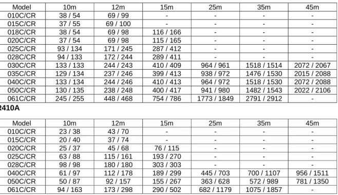
• The refrigerant charge has already charged into the outdoor unit. For the piping length of 7.6m, additional refrigerant charge after vacuuming is not necessary.
• When the piping length is more than 7.6m, please use the table below (unit in gram).
R22
R410A
The additional refrigerant charge amount recommended is a guideline for longer piping application. The actual charge required may be different from the guideline due to different application and variation in site conditions.
Diagram shows typical charging method:
Note : R407C - Fix filter dryer R22 - Nil
R410A - Nil
CAUTION FOR R407C / R410A
Avoid prolong exposure of an opened compressor, or the internal part of refrigerant piping to moist air. The POE oil in the compressor and piping can absorb moisture from air.
Model 10m 12m 15m 25m 35m 45m
010C/CR 38 / 54 69 / 99 - - - -
015C/CR 37 / 55 69 / 100 - - - -
018C/CR 38 / 54 69 / 98 116 / 166 - - -
020C/CR 37 / 54 69 / 98 115 / 165 - - -
025C/CR 93 / 134 171 / 245 287 / 412 - - -
028C/CR 94 / 133 172 / 244 289 / 411 - - -
030C/CR 133 / 133 244 / 243 410 / 409 964 / 961 1518 / 1514 2072 / 2067 035C/CR 129 / 134 237 / 246 399 / 413 938 / 972 1476 / 1530 2015 / 2088 040C/CR 133 / 134 244 / 246 410 / 413 964 / 972 1518 / 1530 2072 / 2088 050C/CR 130 / 135 238 / 248 400 / 417 941 / 980 1482 / 1543 2022 / 2106 061C/CR 245 / 255 448 / 468 754 / 786 1773 / 1849 2791 / 2912 -
Model 10m 12m 15m 25m 35m 45m
010C/CR 23 / 38 43 / 70 - - - -
015C/CR 20 / 40 37 / 74 - - - -
020C/CR 25 / 37 45 / 68 76 / 115 - - -
025C/CR 63 / 88 115 / 161 193 / 270 - - -
028C/CR 98 / 98 180 / 180 303 / 303 - - -
040C/CR 61 / 97 112 / 178 189 / 299 445 / 703 700 / 1107 956 / 1511
050C/CR 50 / 87 92 / 157 155 / 267 363 / 628 572 / 989 781 / 1350
061C/CR 94 / 163 173 / 298 290 / 502 682 / 1179 1075 / 1857 -
R410A is a new HFC refrigerant which does not damage the ozone layer. The working pressure of this new refrigerant is 1.6 times higher than conventional refrigerant (R22), thus proper installation / servicing is essential.
2) Components
Mixture of composition by weight : R32(50%) and R125(50%) 3) Characteristic
• R410A liquid and vapor components have different compositions when the fluid evaporates or condenses. Hence, when leak occurs and only vapor leaks out, the composition of the refrigerant mixture left in the system will change and subsequently affect the system performance. DO NOT add new refrigerant to leaked system. It is recommended that the system be evacuated thoroughly before recharging with R410A.
• When refrigerant R410A is used, the composition will differ depending on whether it is in gaseous or liquid phase.
Hence when charging R410A, ensure that only liquid is being withdrawn from the cylinder or can. This is to make certain that only original composition of R410A is being charged into the system.
• POE oil is used as lubricant for R410A compressor, which is different from the mineral oil used for R22 compressor.
Extra precaution must be taken to avoid exposing the R410A system to moist air.
4) Check List Before Installation / Servicing
• Tubing
Refrigerant R410A is more easily affected by dust or moisture compared with R22, make sure to temporarily cover the ends of the tubing prior to installation
• Compressor oil
No additional charge of compressor oil is permitted.
• Refrigerant
No other refrigerant other that R410A
• Tools (size of service port is different from R22 system)
Tools specifically for R410A only (must not be used for R22 or other refrigerant) i) Gauge manifold and charging hose
ii) Gas leak detector
iii) Refrigerant cylinder/charging cylinder iv) Vacuum pump c/w adapter
v) Flare tools
vi) Refrigerant recovery machine 5) Handling and Installation Guidelines
Like R22 systems, the handling and installation of R410A system are closely similar. All precautionary measures; such as ensuring no moisture, no dirt or chips in the system, clean brazing using nitrogen, and thorough leak check and vacuuming are equally important requirements. However, due to its hydroscopic POE oil, additional precautions must be taken to ensure optimum and trouble-free system operation.
a) During installation or servicing, avoid prolong exposure of the internal part of the refrigerant system to moist air. Residual POE oil in the piping and components can absorb moisture from the air.
b) Ensure that the compressor is not expose to open air for more than the recommended time specified by its manufacturer (typically less than 10 minutes). Removed the seal-plugs only when the compressor is about to be brazed.
c) The system should be thoroughly vacuumed to 1.0 Pa ( 700mmHg) or lower. This vacuuming level is
more stringent than R22 system so as to ensure no incompressible gas and moisture in the system.
composition can be different from the vapor composition.
e) Normally, the R410A cylinder or can is being equipped with a dip-pipe for liquid withdrawal. However, if the dip-pipe is not available, invert the cylinder or can so as to withdraw liquid from the valve at the bottom.
Dip-pipe Invert cylinder
without dip-pipe
Liquid
withdrawal
Sound Power
Duct Discharge Sound Power Level: Test with 5ft length discharge duct, terminated flush with internal wall of reverberation room.
Ext. Static Overall
(mmAq) 125Hz 250Hz 500Hz 1kHz 2kHz 4kHz 8kHz A (dBA)
MCC 010C/CR 5 High 57 54 52 52 51 46 44 57
4 Medium 54 51 50 49 48 43 39 54
3 Low 51 48 47 46 44 39 35 51
MCC 015C/CR 5 High 60 58 57 56 54 48 44 61
4 Medium 56 55 54 53 50 44 40 58
3 Low 52 50 49 48 44 37 34 52
MCC 020C/CR 6.5 High 63 62 61 61 59 55 51 65
6 Medium 61 61 59 60 58 53 49 64
3.5 Low 57 56 56 56 53 48 44 60
MCC 025C/CR 5.5 High 63 52 61 62 59 56 53 66
4 Medium 61 60 59 60 57 53 50 64
3 Low 58 57 56 57 54 49 47 61
MCC 028C/CR 10 Super High 62 65 61 63 60 57 56 67
8 High 59 61 58 61 57 54 52 64
7 Medium 56 57 55 57 54 50 48 61
6 Low 52 53 51 53 50 45 41 57
MCC 030C/CR 21 Super High 68 69 71 72 69 66 65 76
17 High 65 66 68 69 65 63 60 73
13 Medium 61 62 64 65 61 58 55 69
9 Low 56 58 60 61 57 53 49 64
MCC 038C/CR 14 Super High 74 75 74 75 72 70 69 80
12 High 70 70 71 72 68 66 64 76
11 Medium 67 67 68 70 65 62 60 73
9 Low 65 64 65 66 61 58 56 70
MCC 040C/CR 21 Super High 69 71 72 74 71 68 67 78
18 High 65 68 70 72 68 66 64 76
13 Medium 65 65 67 68 64 62 59 72
9.5 Low 59 61 63 64 60 57 54 68
MCC 050C/CR 18 Super High 70 71 73 74 72 69 67 78
16 High 67 69 71 72 69 66 64 76
14 Medium 66 66 69 69 66 63 61 73
11 Low 63 64 66 67 62 60 57 70
MCC 060C/CR 18 Super High 70 71 73 75 73 70 68 79
16 High 69 70 72 74 71 69 68 78
14 Medium 69 68 70 71 67 65 63 75
10 Low 64 65 67 67 63 61 59 71
Model Speed 1/1 Octave A-weighted Sound Power (dB), ref 1pW
Microphone position: 1.4m below the centre of the unit. (GB Standard - GB/D17758)
Tested with 2m length duct at the air discharge outlet and air return inlet.
Measuring Location:
(mmAq) 125Hz 250Hz 500Hz 1kHz 2kHz 4kHz 8kHz A (dBA) Criteria
MCC 010C/CR 5 High 33 30 30 29 22 16 10 33 27
4 Medium 31 28 28 26 20 13 8 30 24
3 Low 28 25 24 22 16 10 7 26 20
MCC 015C/CR 5 High 39 36 34 32 27 18 11 37 31
4 Medium 35 34 32 29 23 14 9 34 27
3 Low 32 29 28 25 17 11 8 29 23
MCC 020C/CR 6.5 High 42 39 36 34 28 22 17 38 33
6 Medium 41 37 34 31 26 20 15 36 30
3.5 Low 40 36 32 29 23 18 13 34 27
MCC 025C/CR 5.5 High 42 41 37 34 31 29 23 40 33
4 Medium 41 40 36 33 29 28 22 39 32
3 Low 36 35 33 31 26 27 21 36 30
MCC 028C/CR 10 Super High 48 45 42 38 34 29 26 44 37
8 High 45 42 39 35 31 26 22 41 34
7 Medium 42 38 37 32 28 22 17 38 32
6 Low 36 33 33 27 23 16 11 34 27
MCC 030C/CR 21 Super High 54 50 46 45 40 34 30 49 44
17 High 50 45 43 42 37 31 26 46 41
13 Medium 45 40 40 38 32 26 20 42 37
9 Low 42 36 37 33 28 22 15 38 32
MCC 038C/CR 14 Super High 56 57 53 50 46 41 36 55 49
12 High 54 51 48 46 41 36 31 51 45
11 Medium 51 48 46 45 37 32 26 48 44
9 Low 47 45 44 41 34 28 22 45 40
MCC 040C/CR 21 Super High 56 49 49 46 41 37 32 51 45
18 High 54 47 47 45 39 35 29 49 44
13 Medium 49 42 43 41 35 31 24 45 40
9.5 Low 45 39 41 37 30 26 18 41 36
MCC 050C/CR 18 Super High 56 50 50 49 44 38 33 53 48
16 High 54 49 49 48 43 37 32 52 47
14 Medium 53 47 46 47 40 35 29 50 46
11 Low 51 45 44 44 36 32 26 47 43
MCC 060C/CR 18 Super High 57 50 51 51 46 39 35 55 50
16 High 55 49 49 50 44 37 33 53 49
14 Medium 53 46 47 47 39 34 28 50 46
10 Low 51 43 44 43 35 30 24 47 42
Model Speed
Test Unit
2m length test duct 2m length test duct
Air
1.4m
Microphone
0 10 20 30 40 50 60 70
125 250 500 1000 2000 4000 8000
Octave-band fre q ue n cy ( Hz )
Sound pressurelevel(dB, ref 20Pa)
M easu red i n anech o ic ro o m a t 1.4 m b e lo w t he cent re o f t he un it Te s ted wi t h 2m lengt h duct at t he ai r di sc h a rge o ut let and ai r r et urn inlet
NC- 4 0 NC- 3 5 NC- 3 0
NC- 2 5 NC- 2 0 NC- 4 5 NC- 5 0
Hi g h fan M edi u m fan
Lo w f an
MCC010C/CR NC Curves
0 10 20 30 40 50 60 70
125 250 500 1000 2000 4000 8000
Octave-band fre qu e ncy ( Hz )
Sound pressurelevel(dB, ref 20Pa)
NC- 4 0 NC- 3 5 NC- 3 0
NC- 2 5 NC- 2 0 NC- 4 5 NC- 5 0
Hi g h fan M ediu m fan
Lo w f an
M easured in anech o ic r o o m at 1 .4m b elow t he cent re of t he unit Test ed wit h 2 m len g t h d uct at t he air dischar g e o utlet and air return inlet
MCC015C/CR NC Curves
0 10 20 30 40 50 60 70
125 250 500 1000 2000 4000 8000
Octave-band frequen cy ( Hz)
Sou nd pr e ss u re lev e l ( d B, r e f 20 Pa)
N C- 4 0 N C- 3 5
N C- 2 0 N C- 4 5 N C- 5 0
Hi g h fan
Lo w f an
N C- 3 0 M ediu m fan
M easu red in an ech o ic ro o m at 1 .4 m b e low t he cent re o f t he un it Te s t ed wit h 2m lengt h du c t at t h e a ir di sch a rge o ut let and a ir r et urn inlet
NC- 2 5 0
10 20 30 40 50 60 70
125 250 500 1000 2000 4000 8000
Octave-band fre quency ( Hz )
Sound pressurelevel(dB, ref 20Pa)
NC- 4 0 NC- 3 5 NC- 3 0
NC- 2 5 NC- 4 5 NC- 5 0
Hi g h fan
Lo w f an M ed ium fan
M easu red in anech o ic ro o m at 1 .4 m b e low t he cent re o f t he unit Te s ted wit h 2m lengt h duct at t he a ir di sc harge o ut le t and air r e turn inl et
MCC025C/CR NC Curves
0 10 20 30 40 50 60 70
125 250 500 1000 2000 4000 8000
Octave-band frequen cy ( Hz)
S o u n d p re ss u re le ve l ( d B , r e f 2 0 Pa )
NC- 4 0 NC- 3 5
N C- 2 0 NC- 4 5 NC- 5 0
S- Hi fan
Lo w f an
Hi g h fan M ediu m fan
N C- 3 0
N C- 2 5
M easu red in an ech o ic ro o m at 1 .4 m b e low t he cent re o f t he un it Te s t ed wit h 2m lengt h du c t at t h e a ir di sch a rge o ut let and a ir r et urn inlet 0
10 20 30 40 50 60
125 250 500 1000 2000 4000 8000
Octave-band fre qu e n cy ( Hz )
Sound pressurelevel(dB, ref 20Pa)
N C- 4 0 N C- 3 5 N C- 3 0
N C- 2 0 N C- 4 5 N C- 5 0
S- Hi fan
Lo w f an Hi g h fan
NC- 2 5 M edi u m
M easu red in an ech o ic ro o m at 1 .4 m b e low t he cent re o f t he un it Te s t ed wit h 2m lengt h du c t at t h e a ir di sch a rge o ut let and a ir r eturn inlet
MCC030C/CR NC Curves
0 10 20 30 40 50 60
125 250 500 1000 2000 4000 8000
Octave-band fre q u e ncy ( Hz )
Sound pressurelevel(dB, ref 20Pa)
N C- 40 N C- 35
NC- 2 5 N C- 2 0 N C- 4 5 N C- 5 0 S- Hi fan
Lo w f an Hi g h fan
NC- 3 0 M ediu m fan
M easu red in an ech o ic ro o m at 1 .4 m b e low t he cent re o f t he un it Te s t ed wit h 2m length du c t at t h e a ir di sch a rge o ut let and a ir r et urn inlet
0 10 20 30 40 50 60 70
125 250 500 1000 2000 4000 8000
Octave-band fre q ue n cy ( Hz )
Sound pressurelevel(dB, ref 20Pa)
NC- 4 0
NC- 2 0 NC- 4 5 NC- 5 0
S- Hi fan
Lo w f an Hi g h fan
NC- 2 5 NC- 3 0
M ediu m fan NC- 3 5
M easu red i n anech o ic ro o m a t 1.4 m b e lo w t he cent re o f t he unit Te s t ed w it h 2m lengt h duct at t he ai r di sch a rge o ut let and ai r r et urn inlet
MCC040C/CR NC Curves
0 10 20 30 40 50 60
125 250 500 1000 2000 4000 8000
Oc tav e-band f requenc y (Hz )
Sound pressure level (dB, ref 20Pa)
N C -4 0
N C -2 5 N C -2 0 N C -4 5 N C -5 0 S-Hi f an
Lo w f an
N C -3 0 Hig h f an
M ed ium
N C -3 5
M eas ured in anec ho ic ro o m at 1.4m belo w t he c ent re o f t he unit T es t ed wit h 2m lengt h duc t at t he air dis c harge o ut let and air return inlet
0 10 20 30 40 50 60 70
125 250 500 1000 2000 4000 8000
Oc tav e-band f requenc y (Hz )
Sound pressure level (dB, ref 20Pa)
N C -4 0
N C -2 0 N C -4 5 N C -5 0 S-Hi f an
Lo w f an
N C -2 5 N C -3 0 Hig h f an
M ed ium
N C -3 5
M eas ured in anec ho ic ro o m at 1.4m belo w t he c entre o f t he unit T es t ed wit h 2m lengt h duc t at t he air dis c harge o ut let and air return inlet
MCC060C/CR NC Curves
FAN PERFORMANCE CURVE MCC 010C/CR
(High Static Motor)
0 2 4 6 8 10 12
0 50 100 150 200 250 300 350 400 450 500
Flowrate , (CFM)
Total St ati c Pressure , (m m w. g.)
1200 RPM
1100 RPM
1000 RPM
900 800 RPM
RPM H
M L
INTERNAL
STATIC
(High Static Motor)
0 2 4 6 8 10 12 14
0 100 200 300 400 500 600 700 800 900 1000
Flowrate , (CFM)
Tot al St at ic Pressur e , ( mm w.g.)
1300 RPM
1200 RPM
1100 RPM
1000 RPM
900 800 RPM
700 RPM RPM H
M
L
INTERNAL
STATIC
MCC 020C/CR (High Static Motor)
0 2 4 6 8 10 12 14 16
0 200 400 600 800 1000 1200
Flowrate , (CFM)
Tot al St at ic Pressur e , ( mm w.g.)
INTERNAL
STATIC RPM 600 700
RPM 800 RPM 900 RPM 1000 RPM 1100 RPM 1200 RPM 1300 RPM
H M
L
1400
RPM
(High Static Motor)
0 2 4 6 8 10 12 14 16
0 200 400 600 800 1000 1200
Flowrate , (CFM)
Tot al St at ic Pressur e , ( mm w.g.)
1400 RPM
1300 RPM
1200 RPM
1100 RPM
1000 RPM 900
RPM 800
RPM INTERNAL
STATIC
H M
L
MCC 028C/CR (High Static Motor)
0 2 4 6 8 10 12 14 16 18 20 22
0 200 400 600 800 1000 1200
Flowrate , (CFM)
Tot al St at ic Pressur e , ( mm w.g.)
1400 RPM
1300 RPM
1200 RPM
1100 RPM
1000 RPM
900 800 RPM RPM SH
H M
L
INTERNAL
STATIC
(High Static Motor)
0 5 10 15 20 25 30
0 200 400 600 800 1000 1200 1400
Flowrate , (CFM)
Tot al St at ic Pressur e , ( mm w.g.)
1400 RPM
1300 RPM
1200 RPM 1100 RPM
1000 RPM
900 RPM 800 RPM
700 RPM SH
H
M
L
INTERNAL
STATIC
MCC 038C/CR (High Static Motor)
0 5 10 15 20 25 30 35
600 800 1000 1200 1400 1600 1800
Flowrate , (CFM)
Tot al St at ic Pressur e , ( mm w.g.)
1400 RPM
1300 RPM
1200 RPM
1100 RPM SH
H M L
INTERNAL
STATIC
(High Static Motor)
0 5 10 15 20 25 30
0 200 400 600 800 1000 1200 1400 1600 1800
Flowrate , (CFM)
Tot al St at ic Pressur e , ( mm w.g.) 1300
RPM
1200 RPM
1100 RPM
1000 RPM
900 800 RPM RPM 700
RPM
SH
H
M
L
INTERNAL
STATIC
MCC 050C/CR (High Static Motor)
0 5 10 15 20 25 30
0 500 1000 1500 2000 2500 3000
Flowrate , (CFM)
Tot al St at ic Pressur e , ( mm w.g.)
SH H
M L
800
RPM 900 RPM
1000
RPM 1100 RPM
1200 RPM
1300 RPM
1400 RPM
INTERNAL
STATIC
(High Static Motor)
0 5 10 15 20 25 30
0 500 1000 1500 2000 2500 3000
Flowrate , (CFM)
Tot al St at ic Pressur e , ( mm w.g.)
SH
H
M
L
14OO RPM
1300 RPM
1200 RPM 1100
1000 RPM RPM
INTERNAL STATIC
900 RPM 800
RPM
MCC 010C/CR (Low Static Motor)
0 2 4 6 8 10 12
0 50 100 150 200 250 300 350 400 450 500
Flowrate, CFM
Tot al S tat ic P re s s ur e , m m .W g.
1200 RPM
1100 RPM
1000 RPM
900 800 RPM
RPM H
M L
INTERNAL
STATIC
(Low Static Motor)
0 2 4 6 8 10 12 14
0 100 200 300 400 500 600 700 800 900 1000
Flowrate , (CFM)
Tot al S tat ic P re ssure , ( mm w.g. )
1300 RPM
1200 RPM
1100 RPM
1000 RPM
900 800 RPM
700 RPM RPM H
M
L
INTERNAL
STATIC
MCC 020C/CR (Low Static Motor)
0 2 4 6 8 10 12 14
0 200 400 600 800 1000 1200
Flowrate , (CFM)
Tot a l Sta ti c Pr ess ure , (mm.w.g. )
INTERNAL
STATIC RPM 600 700
RPM 800 RPM 900 RPM 1000 RPM 1100 RPM 1200 RPM 1300 RPM 1400 RPM
H M
L
(Low Static Motor)
0 2 4 6 8 10 12 14 16
0 200 400 600 800 1000 1200
Flowrate , (CFM)
Tot al S tat ic P re ssure , (mm w.g.) 1400
RPM
1300 RPM
1200 RPM
1100 RPM
1000 900 RPM
800 RPM RPM INTERNAL
STATIC
H M
L
MCC 030C/CR (Low Static Motor)
0 5 10 15 20 25 30
0 200 400 600 800 1000 1200 1400
Flowrate , (CFM)
Total St ati c Pressure , (m m w. g.)
1400 RPM
1300 RPM
1200 RPM
1100 RPM
1000 RPM
900 RPM
800 RPM
700 RPM
SH
H M L
INTERNAL
STATIC
(Low Static Motor)
0 5 10 15 20 25 30
0 200 400 600 800 1000 1200 1400 1600 1800
Flowrate , (CFM)
T o tal S tati c P res su re , (m m w .g .)
1300 RPM
1200 RPM
1100 RPM
1000 RPM
900 RPM 800 RPM 700
RPM
SH
H M L
INTERNAL
STATIC
MCC 050C/CR (Low Static Motor)
0 5 10 15 20 25 30
0 500 1000 1500 2000 2500 3000
Flowrate , (CFM)
T o tal Stati c Pressu re , (mm w .g .)
SH H M L
800 RPM
900 RPM 1000 RPM 1100 RPM 1200 RPM 1300 RPM 1400 RPM
INTERNAL
STATIC
(Low Static Motor)
0 5 10 15 20 25 30
800 1000 1200 1400 1600 1800 2000 2200 2400 2600 2800
Flowrate , (CFM)
Total St ati c Pressure , ( mm w.g.)
H SH L M
1400 RPM
1300 RPM
1200 RPM 1100
1000 RPM
INTERNAL RPM
STATIC RPM 900
800
RPM
M5CC 010C M5CC 015C
M5LC 010C M5LC 015C
Btu/h 9500 12500
W 2780 3660
W 961 1297
A 4.0 5.7
V/Ph/Hz 220 - 240 / 1 / 50 220 / 1 / 50
W/W 2.96 2.91
l/s / CFM 142 / 300 241 / 510
l/s / CFM 123 / 260 208 / 440
l/s / CFM 104 / 220 170 / 360
EXTERNAL STATIC PRESSURE (H/M/L) Pa (in.wg.) 49 / 39 / 29 (0.2 / 0.2 / 0.1) 49 / 39 / 20 (0.2 / 0.2 / 0.1)
dBA 33 / 30 / 26 37 / 34 / 29
mm/in 261 / 10.3 261 / 10.3
mm/in 765 / 30.1 905 / 35.6
mm/in 411 / 16.2 411 / 16.2
mm/in 376 / 14.8 376 / 14.8
mm/in 951 / 37.4 1091 / 43.0
mm/in 541 / 21.3 541 / 21.3
kg/lb 17 / 38 21 / 46
mm/in
l/s / CFM 396 / 840 453 / 960
dBA 46 49
mm/in mm/in mm/in mm/in mm/in mm/in kg/lb
LIQUID mm/in 6.4 / 1/4 6.4 / 1/4
GAS mm/in 9.5 / 3/8 12.7 / 1/2
kg/lb 0.71 / 1.57 0.94 / 2.07
OUTDOOR CAP. TUBE REFRIGERANT CONTROL (EXPANSION DEVICE)
EER
330 / 13.0 620 / 24.4 700 / 27.6 R410A
CONTROL AIR DISCHARGE OPERATION
FLARE VALVE
INDOOR UNIT
DUCTED SLM WIRED HANDSET
19.1 / 3/4 UNIT DIMENSION
32 / 71 810 / 31.9
250 / 9.8 540 / 21.3 SOUND PRESSURE LEVEL (H/M/L)
AIR FLOW
WEIGHT MODEL
OUTDOOR UNIT
LOW
INDOOR UNIT
NOMINAL CAPACITY
NOMINAL TOTAL INPUT POWER NOMINAL RUNNING CURRENT POWER SOURCE
REFRIGERANT TYPE
PACKING
DIMENSION
HEIGHT WIDTH DEPTH HEIGHT WIDTH DEPTH HIGH MEDIUM
UNIT DIMENSION
PACKING DIMENSION
HEIGHT WIDTH DEPTH HEIGHT WIDTH SOUND PRESSURE LEVEL
CONDENSATE DRAIN SIZE
OUTDOOR UNIT
REFRIGERANT CHARGE AIR FLOW
DEPTH UNIT WEIGHT
PIPE CONNECTION
TYPE SIZE
1) ALL SPECIFICATIONS ARE SUBJECTED TO CHANGE BY THE MANUFACTURER WITHOUT PRIOR NOTICE.
2) ALL UNITS ARE BEING TESTED AND COMPLY TO ISO 5151.
3) NOMINAL COOLING AND HEATING CAPACITY ARE BASED ON THE CONDITIONS BELOW : COOLING - 27°C DB / 19°C WB INDOOR AND 35°C DB / 24°C WB OUTDOOR 4) EER/COP CALCULATION IS BASED ON EFFECTIVE POWER INPUT AS PER ISO 5151.
M5LC 020C M5LC 025C
Btu/h 18000 / <18000> 21000 / <22860>
W 5280 / <5280> 6160 / <6700>
W 1757 / <1791> 2003 / <2274>
A 7.6 / <3.4> 8.9 / <4.2>
V/Ph/Hz
W/W 3.13 / <3.07> 3.15 / <3.02>
l/s / CFM 330 / 700 345 / 730
l/s / CFM 321 / 680 340 / 720
l/s / CFM 293 / 620 274 / 580
EXTERNAL STATIC PRESSURE (H/M/L) Pa (in.wg.) 64 / 58 / 34 (0.3 / 0.2 / 0.1) 55 / 39 / 29 (0.2 / 0.2 / 0.1)
dBA 38 / 36 / 34 40 / 39 / 36
mm/in 261 / 10.3 261 / 10.3
mm/in 1065 / 41.9 1200 / 47.2
mm/in 411 / 16.2 411 / 16.2
mm/in 376 / 14.8 376 / 14.8
mm/in 1251 / 49.3 1386 / 54.6
mm/in 541 / 21.3 541 / 21.3
kg/lb 22 / 49 25 / 55
mm/in
l/s / CFM 614 / 1300 689 / 1460
dBA
mm/in 648 / 25.5 750 / 29.5
mm/in 855 / 33.7 855 / 33.7
mm/in 328 / 12.9 328 / 12.9
mm/in 710 / 28.0 810 / 31.9
mm/in 990 / 39.0 990 / 39.0
mm/in 415 / 16.3 415 / 16.3
kg/lb 59 / 130 62 / 137
LIQUID mm/in 6.4 / 1/4 6.4 / 1/4
GAS mm/in 12.7 / 1/2 15.9 / 5/8
kg/lb 1.38 / 3.04 1.60 / 3.53
OUTDOOR UNIT
LOW NOMINAL CAPACITY - 1Ø / <3Ø>
NOMINAL TOTAL INPUT POWER - 1Ø / <3Ø>
NOMINAL RUNNING CURRENT - 1Ø / <3Ø>
POWER SOURCE - 1Ø / <3Ø>
REFRIGERANT TYPE
HIGH
SIZE DEPTH AIR FLOW
WIDTH UNIT DIMENSION
SOUND PRESSURE LEVEL PACKING
DIMENSION
HEIGHT WIDTH DEPTH MEDIUM OPERATION
WIDTH HEIGHT
CONDENSATE DRAIN SIZE AIR FLOW
DEPTH SOUND PRESSURE LEVEL (H/M/L)
WEIGHT EER - 1Ø / <3Ø>
REFRIGERANT CONTROL (EXPANSION DEVICE)
REFRIGERANT CHARGE
19.1 / 3/4
FLARE VALVE
INDOOR UNIT
DUCTED SLM WIRED HANDSET CONTROL AIR DISCHARGE
OUTDOOR UNIT UNIT DIMENSION
PACKING DIMENSION
HEIGHT WIDTH DEPTH HEIGHT
UNIT WEIGHT
PIPE CONNECTION
TYPE
220 - 240 / 1 / 50 / <380 - 415 / 3 / 50>
52 R410A OUTDOOR CAP. TUBE
1) ALL SPECIFICATIONS ARE SUBJECTED TO CHANGE BY THE MANUFACTURER WITHOUT PRIOR NOTICE.
2) ALL UNITS ARE BEING TESTED AND COMPLY TO ISO 5151.
3) NOMINAL COOLING AND HEATING CAPACITY ARE BASED ON THE CONDITIONS BELOW : COOLING - 27°C DB / 19°C WB INDOOR AND 35°C DB / 24°C WB OUTDOOR 4) EER/COP CALCULATION IS BASED ON EFFECTIVE POWER INPUT AS PER ISO 5151.
M5CC 028C M5LC 028C
Btu/h 26000 / <27000>
W 7620 / <7910>
W 2892 / <2876>
A 12.8 / <4.9>
V/Ph/Hz 220 - 240 / 1 / 50 / <380 - 415 / 3 / 50>
W/W 2.73 / <2.85>
R410A OUTDOOR CAP. TUBE
DUCTED SLM WIRED HANDSET
l/s / CFM 401 / 850
l/s / CFM 382 / 810
l/s / CFM 363 / 770
l/s / CFM 335 / 710
EXTERNAL STATIC PRESSURE (H/M/L) Pa (in.wg.) 98 / 78 / 68 / 59 (0.4 / 0.3 / 0.3 / 0.2)
dBA 44 / 41 / 38 / 34
mm/in 285 / 11.2
mm/in 1007 / 39.7
mm/in 600 / 23.6
mm/in 343 / 13.5
mm/in 1138 / 44.8
mm/in 690 / 27.2
kg/lb 38 / 84
mm/in 19.1 / 3/4
l/s / CFM 684 / 1450
dBA 54
mm/in 750 / 29.5
mm/in 855 / 33.7
mm/in 328 / 12.9
mm/in 810 / 31.9
mm/in 990 / 39.0
mm/in 415 / 16.3
kg/lb 68 / 150
FLARE VALVE
LIQUID mm/in 9.5 / 3/8
GAS mm/in 15.9 / 5/8
kg/lb 1.80 / 3.97
EER - 1Ø / <3Ø>
REFRIGERANT CONTROL (EXPANSION DEVICE) CONTROL AIR DISCHARGE
OPERATION
SOUND PRESSURE LEVEL (H/M/L) AIR FLOW
SUPER HIGH
INDOOR UNIT
UNIT DIMENSION
WEIGHT MODEL
OUTDOOR UNIT
LOW
INDOOR UNIT
NOMINAL CAPACITY - 1Ø / <3Ø>
NOMINAL TOTAL INPUT POWER - 1Ø / <3Ø>
NOMINAL RUNNING CURRENT -1Ø / <3Ø>
POWER SOURCE - 1Ø / <3Ø>
REFRIGERANT TYPE
PACKING
DIMENSION
HEIGHT WIDTH DEPTH HEIGHT WIDTH DEPTH HIGH MEDIUM
UNIT DIMENSION
PACKING DIMENSION
HEIGHT WIDTH DEPTH HEIGHT WIDTH SOUND PRESSURE LEVEL
CONDENSATE DRAIN SIZE
OUTDOOR UNIT
REFRIGERANT CHARGE AIR FLOW
DEPTH UNIT WEIGHT
PIPE CONNECTION
TYPE SIZE
M5LC 035C M5LC 040C Btu/h 32000 / <33000> <39000>
W 9380 / <9670> <11430>
W 3287 / <3427> <4173>
A 15.2 / <5.9> <7.4>
V/Ph/Hz
W/W 3.07 / <3.03> <2.88>
l/s / CFM l/s / CFM l/s / CFM l/s / CFM EXTERNAL STATIC PRESSURE (H/M/L) Pa (in. wg.)
dBA mm/in mm/in mm/in mm/in mm/in mm/in kg/lb mm/in l/s / CFM
dBA mm/in mm/in mm/in mm/in mm/in mm/in kg/lb
LIQUID mm/in
GAS mm/in
kg/lb 2.6 / 5.73 2.175 / 4.80
REFRIGERANT CHARGE
UNIT WEIGHT 95 / 209
PIPE CONNECTION
TYPE FLARE VALVE
SIZE 9.5 / 3/8
15.9 / 5/8
DEPTH 400 / 15.8
PACKING DIMENSION
HEIGHT 1000 / 39.4
WIDTH 1200 / 47.2
DEPTH 560 / 22.1
OUTDOOR UNIT
AIR FLOW 1605 / 3400
SOUND PRESSURE LEVEL 58
UNIT DIMENSION
HEIGHT 850 / 33.5
WIDTH 1030 / 40.6
WEIGHT 41 / 90
CONDENSATE DRAIN SIZE 19.1 / 0.75
PACKING
DIMENSION
HEIGHT 355 / 14.0
WIDTH 1461 / 57.5
DEPTH 727 / 28.6
118 / 96 / 78 / 61 (0.47 / 0.39 / 0.31 / 0.24)
SOUND PRESSURE LEVEL (H/M/L) 52 / 49 / 47 / 45
UNIT DIMENSION
HEIGHT 305 / 12.0
WIDTH 1302 / 51.3
DEPTH 638 / 25.1
546 / 1160
MEDIUM 495 / 1050
LOW 433 / 920
INDOOR UNIT
CONTROL AIR DISCHARGE DUCTED
OPERATION SLM WIRED HANDSET
AIR FLOW
SUPER HIGH 603 / 1280
HIGH
REFRIGERANT CONTROL (EXPANSION DEVICE) OUTDOOR CAP. TUBE
NOMINAL TOTAL INPUT POWER - 1Ø / <3Ø>
NOMINAL RUNNING CURRENT - 1Ø / <3Ø>
POWER SOURCE - 1Ø / <3Ø> 220 - 240 / 1 / 50 / <380 - 415 / 3 / 50>
NOMINAL COOLING CAPACITY - 1Ø / <3Ø>
EER - 1Ø / <3Ø>
REFRIGERANT TYPE R410A
OUTDOOR UNIT
1) ALL SPECIFICATIONS ARE SUBJECTED TO CHANGE BY THE MANUFACTURER WITHOUT PRIOR NOTICE.
2) ALL UNITS ARE BEING TESTED AND COMPLY TO ISO 5151.
3) NOMINAL COOLING AND HEATING CAPACITY ARE BASED ON THE CONDITIONS BELOW : a) COOLING - 27°C DB / 19°C WB INDOOR AND 35°C DB / 24°C WB OUTDOOR b) HEATING - 20°C DB INDOOR AND 7°C DB / 6°C WB OUTDOOR
4) EER/COP CALCULATION IS BASED ON EFFECTIVE POWER INPUT AS PER ISO 5151.
1) ALL SPECIFICATIONS ARE SUBJECTED TO CHANGE BY THE MANUFACTURER WITHOUT PRIOR NOTICE.
2) ALL UNITS ARE BEING TESTED AND COMPLY TO ISO 5151.
3) NOMINAL COOLING AND HEATING CAPACITY ARE BASED ON THE CONDITIONS BELOW : COOLING - 27°C DB / 19°C WB INDOOR AND 35°C DB / 24°C WB OUTDOOR 4) EER/COP CALCULATION IS BASED ON EFFECTIVE POWER INPUT AS PER ISO 5151.
M5CC 050C M5CC 060C
M5LC 050C M5LC 061C
Btu/h 48000 54500
W 14070 15970
W 5115 5758
A 8.9 9.7
V/Ph/Hz 380 - 415 / 3 / 50 380 - 415 / 3 / 50
W/W 2.94 2.98
l/s / CFM 675 / 1430 812 / 1720
l/s / CFM 623 / 1320 732 / 1550
l/s / CFM 580 / 1230 632 / 1340
l/s / CFM 533 / 1130 552 / 1170
EXTERNAL STATIC PRESSURE (H/M/L) Pa (in.wg.) 147 / 126 / 109 / 92 (0.6 / 0.5 / 0.4 / 0.4) 147 / 120 / 90 / 69 (0.6 / 0.5 / 0.4 / 0.3)
dBA 54 / 53 / 52 / 51 54 / 52 / 49 / 46
mm/in 378 / 14.9 378 / 14.9
mm/in 1299 / 51.1 1499 / 59.0
mm/in 541 / 21.3 541 / 21.3
mm/in 415 / 16.3 415 / 16.3
mm/in 1497 / 59.0 1701 / 67.0
mm/in 631 / 24.8 631 / 24.8
kg/lb 54 / 119 62 / 137
mm/in
l/s / CFM 2171 / 4600 2171 / 4600
dBA 68 65
mm/in 850 / 33.5 850 / 33.5
mm/in 1030 / 40.6 1030 / 40.6
mm/in 400 / 15.8 460 / 18.1
mm/in 1000 / 39.4 1016 / 40.0
mm/in 1200 / 47.2 1178 / 46.4
mm/in 560 / 22.1 602 / 23.7
kg/lb 105 / 232 108 / 238
LIQUID mm/in 9.5 / 3/8 9.5 / 3/8
GAS mm/in 15.9 / 5/8 19.1 / 3/4
kg/lb 2.73 / 6.01 3.3 / 7.27
EER
REFRIGERANT CONTROL (EXPANSION DEVICE) CONTROL AIR DISCHARGE
OPERATION
SOUND PRESSURE LEVEL (H/M/L) AIR FLOW
SUPER HIGH
R410A
MEDIUM
OUTDOOR CAP. TUBE & TXV
FLARE VALVE
INDOOR UNIT
DUCTED SLM WIRED HANDSET
19.1 / 3/4 UNIT DIMENSION
WEIGHT PACKING
DIMENSION
HEIGHT WIDTH MODEL
OUTDOOR UNIT
LOW
INDOOR UNIT
NOMINAL CAPACITY
NOMINAL TOTAL INPUT POWER NOMINAL RUNNING CURRENT POWER SOURCE
REFRIGERANT TYPE
HIGH
DEPTH HEIGHT WIDTH DEPTH
UNIT DIMENSION
PACKING DIMENSION
HEIGHT WIDTH DEPTH HEIGHT WIDTH SOUND PRESSURE LEVEL
CONDENSATE DRAIN SIZE
OUTDOOR UNIT
REFRIGERANT CHARGE AIR FLOW
DEPTH UNIT WEIGHT
PIPE CONNECTION
TYPE SIZE