Air-conditioner Network System
Centralized Controller
Model: AG-150A Instruction Book
(Web browser for Initial Settings)
Contents
1 Introduction ...1
1-1 Terms Used in This Manual ... 1
1-2 Computer Requirements ... 1
1-3 Notes on using AG-150A with the integrated centralized control software (TG-2000A)... 1
2 Setting the Operating Environment ...2
2-1 Setting the PC IP Address... 2
2-2 Setting the Web Browser... 4
3 Performing Operations ...6
3-1 Logging in on the AG-150A ... 6
4 Initial Settings...9
4-1 Setting the Current Date and Time... 9
4-2 Setting the Basic Information and External Input Functions . 10 4-3 Group Setting ... 18
4-4 Interlocked Setting... 20
4-5 Block Setting... 21
5 Functions 1...22
5-1 Error mail reports/E-mail communication ... 22
5-2 Energy-Save Control and Peak Cut Control ... 25
5-3 Settings for measurement ... 30
6 Functions 2...34
6-1 Limiting the Set Temperature Operating Range ... 34
6-2 Night Mode (Silent Mode) Schedule... 35
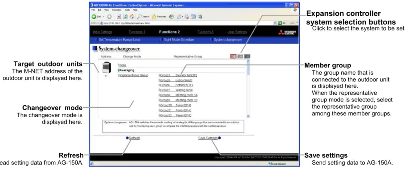
6-3 System-Changeover of Y series... 36
7 Functions 3...37
7-1 External Temperature Interlock ... 37
7-2 Night setback control... 38
7-3 Interlock control ... 39
8 User Setting ...42
9 Registering a License for Optional Function ...44
1 Introduction
Special features of Mitsubishi Electric Corporation’s “Centralized Controller AG-150A” is that a PC connected to a LAN can be used to monitor the operation condition of air conditioners, perform air conditioner operations, and make initial settings.
This document explains the procedures for making initial settings for the Centralized Controller AG-150A using the web browser.
Hereinafter, the centralized controller AG-150A, unless otherwise specified, will be called "AG-150A".
Note: License of "Web Monitor" or "Basic License Pack" is necessary to use the web browser and update program. Register the license key on the AG-150A LCD screen.
A one-day license key can be registered on the LCD screen that allows the user to use the "Web Monitor" only on the day of the registration. Use this license key to update the program or to use the initial setting browser, or in any other situations when a temporary license key is necessary.
Note: Use a security device such as a VPN router when connecting the AG-150A to the Internet to prevent unauthorized access.
Note: "Booster unit" and "Water HEX unit" are referred to as "Air to water".
1-1 Terms Used in This Manual
- “Click” refers to the action of positioning the mouse cursor on the object (such as button or folder), pressing down, and releasing the left mouse button once.
- Unless otherwise specified, the example screen images used in this manual are Windows XP® and Internet Explorer 6.0 screen images.
Note: Windows is a registered trademark or trademark of Microsoft Corporation USA in the United States and other countries.
- The K transmission converter (PAC-SC25KAA) and OA processing unit (LOSSNAY) are not included in systems shipped to North America (USA & Canada).
1-2 Computer Requirements
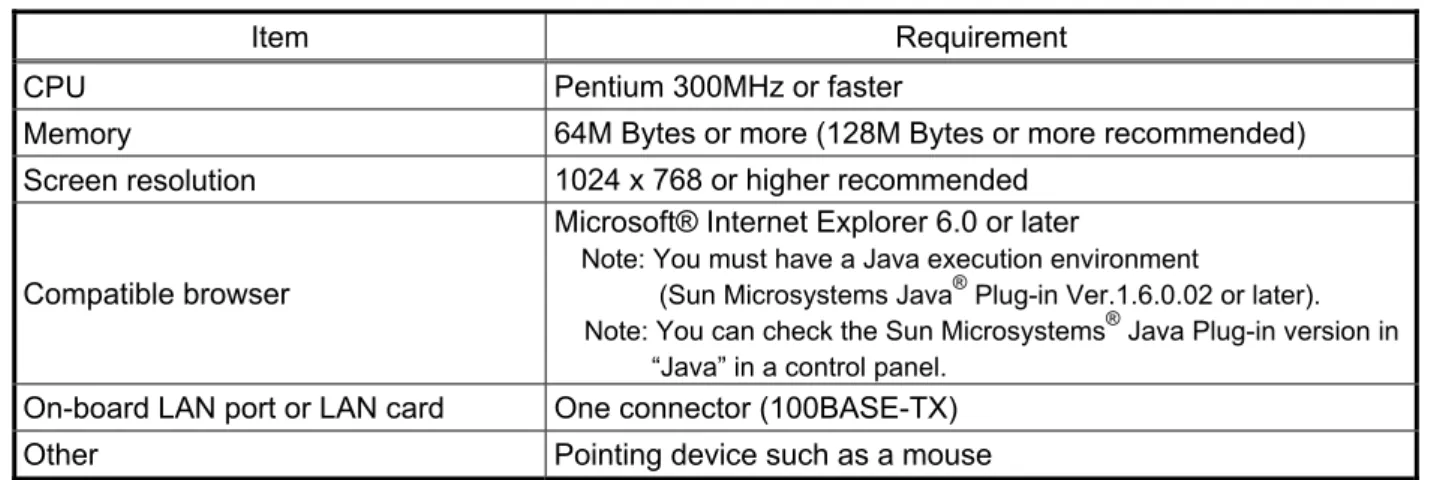
To monitor and operate air conditioners by web browser, computer must include the following requirements.
Table 1-1 Computer Requirements
Item Requirement
CPU Pentium 300MHz or faster
Memory 64M Bytes or more (128M Bytes or more recommended)
Screen resolution 1024 x 768 or higher recommended
Compatible browser
Microsoft® Internet Explorer 6.0 or later
Note: You must have a Java execution environment
(Sun Microsystems Java® Plug-in Ver.1.6.0.02 or later).
Note: You can check the Sun Microsystems® Java Plug-in version in
“Java” in a control panel.
On-board LAN port or LAN card One connector (100BASE-TX)
Other Pointing device such as a mouse
Note: Microsoft is a registered trademark or trademark of Microsoft Corporation USA in the United States and other countries.
Sun Microsystems and Java are trademarks or registered trademarks of Sun Microsystems Inc. in the United States and/or other countries.
1-3 Notes on using AG-150A with the integrated centralized control software (TG-2000A)
If the system is connected to the integrated centralized control software (referred to as TG-2000A hereafter), make all settings and changes from the TG-2000A so that the data in TG-2000A and AG-150A will match.
2 Setting the Operating Environment
PC settings and web browser settings required for using a web browser to monitor air conditioner units and perform operations are explained in the following pages.
2-1 Setting the PC IP Address
Set an IP address on the PC that enables AG-150A to connect via a web browser. For instance, if the AG-150A IP address is [192.168.1.1], the PC IP address will need to belong to the same system [192.168.1.101].
If the AG-150A is connected to an existing LAN, ask the LAN administrator to decide what PC IP address to use.
Note: When using a AG-150A dedicated LAN, it is recommended that the AG-150A main unit be given an IP address within the range [192.168.1.1] - [192.168.1.40] and the PCs that will be connected to the AG-150A be given an IP address within the range [192.168.1.101] - [192.168.1.150]
(1) Click on [Control Panel] under [Start] to open the Control Panel.
(2) In the Control Panel window, double click [Network and Dial-up Connections] and the Network and Dial-up Connections window will open. Double click on [Local Area Setting] and the [Local Area Connection Status] dialog will open. Click [Properties].
(3) In the [Local Area Connection Properties] dialog, click [Internet Protocol] to select it and click the [Properties] button.
(4) In the [Internet Protocol (TCP/IP) Properties] dialog, click [Use the following IP address] and enter the IP address (for example,
“192.168.1.101”) that you want to set in the IP address field.
You normally set [255.255.255.0] as the subnet mask.
Note: Ask your LAN administrator to provide the IP addresses and subnet mask.
(5) Click the [OK] button to close this dialog, and then close the other open dialogs to complete the network setting.
2-2 Setting the Web Browser
Necessary web browser settings must be performed to enable the web browser to connect to the AG-150A.
Note: The settings and screen images used as examples in this manual are based on Internet Explorer 6.0.
2-2-1 No Internet Connection
Follow the instructions below to make the web browser environment settings when using the PC with no Internet connection for monitoring and operating the air conditioners.
(1) Click the web browser menu item [Tools] and then click [Internet Options…] to select.
(2) In the [Internet Options] tabbed dialog, click the [Connections] tab to display.
(3) Select [Never dial a connection] in the Dial-up settings section and click the [OK] button to close the dialog.
2-2-2 Internet Connection Using a Dial-Up
If the PC used for monitoring air conditioners and performing operations is going to connect to the Internet via a dial-up connection, use the procedure given below to set the web browser environment settings.
By performing these settings, a message will appear asking whether or not to use a dial-up connection when an Internet connection is necessary. When connecting to the Internet, follow the directions below.
(1) Click the web browser menu item [Tools] and then click [Internet Options…] to select.
(2) In the [Internet Options] tabbed dialog, click the [Connections] tab to display.
Use a security device such as a VPN router when connecting the AG-150A to the Internet to prevent unauthorized access.
If no security devices are installed, the operation settings may be changed by an unauthorized person without the knowledge of the user.
2-2-3 Connecting to the Internet using a proxy server (Using an existing LAN)
If the PC you use for monitoring air conditioners and performing operations is going to access the Internet via proxy server by connecting to an existing LAN such as a LAN within your company, use the procedure given below to set the web browser environment settings.
By performing these settings, your PC will connect to a proxy server only when connecting to the Internet.
(1) Click the web browser menu item [Tools] and then click [Internet Options…] to select.
(2) In the [Internet Options] tabbed dialog, click the [Connections] tab to display.
(3) Select [Never dial a connection] in the Dial-up setting section.
(4) Click the [LAN Setting . . .] button in the Local Area Network (LAN) settings section to display the Local Area Network (LAN) Settings dialog.
(5) In the Local Area Network (LAN) Settings dialog, check [Bypass proxy server for local addresses] and click the [Advanced...] button.
(6) Enter the IP address for the AG-150A (e.g. 192.168.1.1) in the Exceptions field of the Proxy Setting dialog and click the [OK] button to close the dialog and then close the other open dialogs to complete the setting.
Note: If connecting to more than one AG-150A, you can specify multiple IP addresses like [192.168.1.1; 192.168.1.2], however, it is also possible to use the asterisk (*) and specify [192.168.1.*].
3 Performing Operations
Text below explains how to connect to the AG-150A and how to make various settings for the AG-150A.
Note: If the AG-150A is restarted due to a power interruption etc., wait until the screen on the AG-150A main unit displays the normal operation screen (it takes several minutes before the normal operation screen is displayed) before using a web browser to access the AG-150A. If access is attempted while the AG-150A is still starting up, the most recent data might not be displayed or communication errors could occur.
Note: Default IP address of AG-150A is "192.168.1.1". (Factory setting)
3-1 Logging in on the AG-150A
3-1-1 Logging in on the AG-150A
(1) Enter the web page address in the address field of the web browser as follows:
http :// [IP address of the AG-150A]/g-50 /administrator.html
Press the [Enter] key on the keyboard. A screen appears for login.
Note: For example, type “http ://192.168.1.1/g-50/administrator.html” if the AG-150A IP address is [192.168.1.1].
(2) To make connection easier for the next time, click the web browser menu item [Favorites], click [Add to Favorites], then add the address to the Favorites folder. Once this address is added to the Favorites folder, it is not necessary to input the address of (1).
Simply select it from the Favorites folder and the AG-150A page will appear.
(3) Enter the user name and the password in the login screen, and click the [Login] button. A screen will appear in which various setting are made. An explanation on how to perform operations begins from the next page.
The table below shows the default user names and passwords for maintenance users and building managers as well as available functions.
User Default
user name Default
password Available functions
Initial settings Date and Time, Basic System, Groups, Interlocked LOSSNAY, Blocks Functions 1 E-Mail, Peak cut, Measurement
Functions 2 Set Temperature Range Limit, Night Mode Schedule, System-changeover
Functions 3 Interlock control based on outside temperature, Setback control
Interlock control Maintenance
user initial init
User Settings User Settings Building
manager administrator admin Out of the functions listed above, the items to which access rights have been given on the user settings screen are available.
Note: The user name and the password for building manager are the same as those of the building manager of the Web for monitoring/operation.
Note: Maintenance users can make available to the administrator only the information necessary for normal operations (group name setting etc.)
Note: It is recommended to change the user name and password so users other than the manager are not permitted to change the settings.
Note: The Web page is displayed in the same language as the computer uses and it is also possible to display the Web page in
3-1-2 Encrypting the communication data and login on the AG-150A
AG-150A can encrypt communication data using HTTPS (SSL).
When connecting the AG-150A to the LAN that can be accessed by the general public, it is recommended that the following settings be made so that the units are monitored and controlled on the encrypted Web page.
Note: Depending on the operating system or the version of Java, HTTPS encrypted messages may not be handled correctly. If this happens, use a HTTP connection to monitor and control the units as noted in the section above.
(1) Go to [Tools]->[Internet Options]->[Advanced], and make the following settings.
Item Checkbox setting
Use SSL 2.0 Uncheck the box.
Use SSL 3.0 Check the box.
Use TLS 1.0 Uncheck the box.
Do not save encrypted pages to disk Check the box.
Note: Some of the settings may have different names depending on the Web browser version.
(2) Click on [Java] in the Control Panel, and make the settings for the items under [Security] in the [Advanced] tab.
Item Checkbox setting
Use SSL 2.0 compatible Client Hello format Uncheck the box.
Use SSL 3.0 Check the box.
Use TLS 1.0 Uncheck the box.
Note: Some of the settings may have different names depending on the Java version.
(3) Prefix the Web address with [https], enter the address, and hit the [Enter] (Return) key on the keyboard.
https ://[IP Address of the AG-150A]/g-50
/administrator.html
Note: For example, type “https ://192.168.1.1/g-50/administrator.html” if the AG-150A IP address is [192.168.1.1].
If the security alert is disabled as described in the note in the following and the subsequent sections, encrypted date
communication will begin, and the Login screen will appear. If the security alert has not been disabled, take the following procedures.
(4) If the security alert has not been disabled, after entering the web address and hitting the Enter (Return) key, a security alert message will alert asking if you want to proceed . This is because the AG-150A uses the self-authentication system. Click [Yes] and proceed.
Note: Disable the security alert that appears every time the browser is opened, take the following two steps:
1) Register the security certificate and 2) Change the Web browser's option settings
To register the security certificate, click the [View Certificate] button on the security alert window to display the certificate, click on the [Install Certificate] button, and add the certificate to the Trusted Root Certification Authorities store. Just follow the prompts of the Import Wizard.
Go to [Tools]->[Internet Options]->[Advanced], and make the following settings for the Web browser.
Item Checkbox setting
Warn about invalid site certificates Uncheck the box.
(5) A Java security alert message will appear after you click [Yes] in step (4) above, click [Yes] again to proceed.
Note: To disable the security alert message that appears every time the browser is opened, check the check box next to [Always trust content from this publisher], and click [Yes]. The browser may need to be restarted to reflect the change.
Note: If the window shown on the right does not appear and connection fails, the certificate needs to be added to the Java certificate list. Click the [View Certificate] button on the screen in step (4) to display the certificate, click on the [Copy to File] on the [Details] page, and save the
certificate in any desired location in the DER format. Open [Java] in the Control Panel, click on the [Certificates] button on the [Security] page to bring up the certificate registration screen. On the screen, select [Secure Site], click on the [Import]
button, change the File of type to [All Files], and select the saved certificate. Now the certificate has been added to the Java certificate list.
(6) If a connection is successfully made, the login window will appear.
All communication with the AG-150A will be encrypted. The Web addresses for general users and in each language will have the web address in the previous section with "http" changed to "https".
4 Initial Settings
4-1 Setting the Current Date and Time
Click [Initial Settings] in the menu, and [Date and Time] screen will appear on the screen. Enter the current date and time, and then press the [Save Settings] button to send the current date and time to AG-150A.
Note: If the user logs in as a building manager, the operations may be prohibited.
Note: If the system is connected to the TG-2000A, make all settings and changes from the TG-2000A so that the data in TG-2000A and AG-150A will match.
Note: When the time setting is made on this screen, the setting will be applied to all the units on M-NET system.
Note: When the DIDO controller (PAC-YG66DCA), AI Controller (PAC-YG63MCA), or PI Controller (PAC-YG60MCA) is newly connected, make the time setting of the connected controller on this screen.
Item Description
Current date/time Enter the current date and time.
For the date, use the format [day - month - year].
Save Settings Click the [Date/Time Set] button to set the current date and time.
Refresh Acquires the current Date and Time from AG-150A.
Summer time setting
Click and tick the "Automatically adjust clock for daylight saving changes" box to adjust the daylight saving time automatically, and select the applicable country.
Note: If the applicable country is not in the selection bar, select "Custom Settings". Click "Custom Settings" button that will appear on the right to set the daylight saving time.
Custom Setting Screen
Current date/time
Enter the current date and time here.
Save settings
Click to set the current date and time.
Summer time setting
Click to set the daylight saving time.
Refresh Acquires the current Date and Time from AG-150A.
Daylight saving date and time
Set the daylight saving time.
4-2 Setting the Basic Information and External Input Functions
Display the page needed to perform the AG-150A basic setting by clicking [Initial Settings]-[Basic System] in the setting menu pane. On this page, you perform the basic setting such as the AG-150A unit name, network setting and M-NET setting. Click [Save Settings] to send setting data to the AG-150A. After the setting data are sent to the AG-150A, a message will appear asking whether or not to restart the AG-150A. Click [OK] to restart the AG-150A to put the changes into effect.
Note: If the user logs in as a building manager, the operations may be prohibited.
4-2-1 AG-150A Unit Setting
In Unit Setting, set the AG-150A name and unit ID.
(1) Enter the AG-150A unit name in the [Name] field. You may enter a maximum of 40 alphanumeric or symbol characters. The name set here is used on the display screen of the software that controls multiple AG-150A units and for the name of the sender in the body of error messages.
Note: The following characters cannot be used in the name: < > & " '
(2) Enter the AG-150A unit ID in the [Unit ID] field. You must enter 6 numeric characters. Use this setting when you want to control multiple AG-150A units with unit IDs. The unit ID that is entered here will be used on the display screen of the software that controls multiple AG-150A units and for the sender ID in the body of error messages.
(3) When [Refresh] is clicked, the AG-150A production ID will appear in the [SERIAL No.] field and the AG-150A software version will appear in the [Software Version] field.
Unit Setting Set the AG-150A name and unit ID.
Network Setting Set the AG-150A IP address and subnet mask.
M-NET Setting
Set the AG-150A M-NET address, presence/absence of K-Control units and range of prohibited controllers.
External Input Setting Set the AG-150A external input setting.
Display Format Set the items related to the screen display on the AG-150A or on the Web.
Save Settings
Send setting data to AG-150A.
Refresh Read setting data from AG-150A.
Use or non-use of expansion controller
Select from “Do not use” or
“Use.”
System configuration settings Set the use or non-use of expansion controller, connection target, M-NET settings, and external input settings.
Expansion controller system selection buttons
4-2-2 Configuring the System Configuration Settings
In the System Configuration Settings menu, set the use or non-use of PAC-YG50ECA expansion controller, connection target, M-NET settings, and external input settings.
4-2-2-1 Setting the Expansion Controller Connection Setting
In the M-NET Settings menu, set the use or non-use of PAC-YG50ECA expansion controller and connection target settings.
(1) Select from “Do not use” or “Use” to set the use or non-use of an expansion controller.
*Before setting the expansion controller setting to “Use,” make sure that the expansion controller is connected to the LAN. The settings made without the expansion controller being connected may not be saved (M-NET settings, external input settings, group settings, LOSSNAY interlock settings etc., which are saved on the expansion controller side.)
(2) If “Use” is selected for the Expansion Controller setting, an IP address input field will appear under “Access Point Settings.”
Enter the IP address that is assigned to the expansion controller here.
When connecting two expansion controllers, first click [EC1] and
enter the IP address for the first expansion controller system, and then click [EC2] to enter the IP address for the second expansion controller system.
*Set the IP address for the expansion controller itself on the expansion controller unit.
(3) After the expansion controller connection setting or the IP address of the expansion controller was changed, click the [Save] button and restart the G-150AD by following the messages on the screen. Make the M-NET settings and external input settings after the system has been restarted.
* To change the settings for the external input settings (or any other settings that are saved on the expansion controller side) after the M-NET settings have been made, restart the controller and change the settings with the expansion controller properly being connected to the system.
*After connecting the expansion controller, check that the database number (DB No.) on the controller itself and the data base number of the expansion controller match. If they do not, consult your dealer for software upgrade.
4-2-2-2 M-NET Setting
In M-NET Setting, set the AG-150A M-NET address, whether or not a K-Control unit is present and which machines send the prohibited controller command.
(1) Enter the AG-150A M-NET address in the [M-NET Address] field. Normally you should enter [0].
(2) When K-Control air conditioners are connected, click [Used] in the [K-Control Units] field and enter the M-NET address of K transmission converter in the [K Converter Address] field.
(3) If prohibited controller (prohibiting local operation) has been set, this setting determines the scope of this setting s control, i.e. operation is prohibited for both the remote control and subordinate system controllers, or just for the remote control. Click [SC/RC] when you want prohibited controllers to include both subordinate system controllers and the remote control, or click [RC only] when you only want to prohibit operation on the remote control.
Note: Normally, you should select [SC/RC].
4-2-2-3 External Input Setting
In the External Input Setting menu, set the AG-150A external input function. By using external input functions, it is possible to stop and run multiple air conditioners connected to the AG-150A via the separately sold external I/O adapter for AG-150A (Model: PAC-YG10HA) using level signals and pulse signals.
* If PAC-YG50ECA expansion controllers are connected, expansion controller system selection buttons will appear. Select the desired expansion system controller, and make the settings for each system. Make the settings with the expansion controllers properly connected. Connect the external input signal wires to each controller’s external input terminal.
(1) Select [Not in use] when not using the external input function.
(2) Selecting [Emergency stop (Level signal)] makes it possible to stop multiple units by using a level signal.
While this stop operation is being performed, operations such as running or stopping units are prohibited on the AG-150A unit or remote control.
(3) Selecting [ON/OFF (Level signal)] makes it possible to run or stop multiple units using a level signal. In this mode, all air conditioner units connected to the AG-150A will be run or stopped and run/stop operations will be prohibited on the AG-150A unit or remote control.
Contact ON Contact OFF
Normal Emergency
Stop Normal
Contact ON Contact OFF
Stop Run Stop
Run/Stop
Connection to AG-150A (CN5) DC12V 1 2
3 4 5 6 7 8 9
Emergency stop/normal
Connection to AG-150A (CN5) DC 12V 1 2
3 4 5 6 7 8 9
(4) Selecting [ON/OFF/Prohibit/Permit (Pulse signal)] makes it possible to use pulse signals to run multiple units, stop multiple units, prohibit local operation and permit local operation. In this mode, it is possible to freely operate the remote control except during the pulse signal input.
Contact ON Contact OFF
Contact ON Contact OFF
Stop Run Stop
0.5 - 1.0 Seconds Run
Stop
Contact ON Contact OFF
Contact ON Contact OFF
Permit Prohibit Permit
0.5 - 1.0 Seconds Prohibit
Permit
Connection to AG-150A (CN5)
DC12V Run
Stop
Prohibit Permit
:Pulse generator 12
34 56 78 9
4-2-3 Network Setting
In Network Setting, set the AG-150A IP address, subnet mask and gateway address. If connecting to the AG-150A via a permanent LAN, consult with the network administrator before setting these addresses.
4-2-3-1 Settings for when the AG-150A is connected to a dedicated LAN
(1) Enter the AG-150A IP address in the [IP Address] field. If the LAN wiring has been newly set up, allocate IP addresses to the AG-150A units in a sequential order starting with [192.168.1.1]. For example the first AG-150A unit will receive an IP address of [192.168.1.1], the second AG-150A unit will receive an IP address of [192.168.1.2] and so on.
The Web Monitor PC that monitors and sets AG-150A will also require network addresses consistent with the rest of the LAN.
Note: When using a AG-150A dedicated LAN, it is recommended to set the IP address as follows.
AG-150A: Between [192.168.1.1] and [192.168.1.40] Web Monitor PC: Between [192.168.1.101] and [192.168.1.150]
[Example of IP address setting]
(2) Enter the AG-150A subnet mask in the [Subnet Mask] field. Normally, you should enter [255.255.255.0].
(3) When monitoring remotely or sending error mail via a dial-up router, enter the router IP address in the [Gateway]
field.
Leave the gateway address blank when not connecting via a dial-up router.
[Example of a Remote Monitoring System]
Web Monitor PC AG-150A No. 1 AG-150A No. 2 AG-150A No. 3
100BASE-TX LAN straight cable Hub
192.168.1.101 192.168.1.1 192.168.1.2 192.168.1.3
AG-150A IP Address :192.168.1.1 Subnet Mask :255.255.255.0 G/W Address :192.168.1.254
Telecommunication Network
Dial-up router Dial-up router, cellular phone etc.
Note: Some hubs have a dedicated port for connection with another hub.
Connect the AG-150A and Web Monitor PC to the normal ports.
Note: It is recommended to set the dial-up router IP address to [192.168.1.254]. Refer to the dial-up router instruction manual for details of how to set the IP address.
Note: It is necessary to connect a modem (analog type or ISDN type) between the dial-up router and telephone line when using a dial-up router that does not have a built-in modem.
IP: 192.168.1.254
Web Monitor PC Web Monitor PC
IP Address :192.168.1.101 Subnet Mask :255.255.255.0 G/W Address :Blank
4-2-3-2 Settings for when the AG-150A is connected to an existing LAN
When connecting the AG-150A to an existing LAN, consult with the network administrator who is responsible for the LAN before setting the IP address, subnet mask, or gateway address.
[Example of a Permanent LAN System]
4-2-4 Setting the Display Format
Set the items related to the screen display in the [Display Format] field.
(1) In the [Unit of Temperature] section, select between [ºC] and [ºF] as the unit of temperature.
(2) In the [Date Format] section, select the display order of year/month/day. The date will be displayed in the selected order on the Web screen or on the mail screen.
Note: Set the format of the date to be displayed on the LCD on the LCD Setting screen.
(3) In the [Time Format] section, select the display of time format. The time will be displayed in the selected format on the Web screen.
Note: Set the format of the time to be displayed on the LCD on the LCD Setting screen.
(4) In the [Group Names on Overview Monitor] section, select [ON] to display the group name under the icon on the [Monitor / Operation (Overview)] screen and select [OFF] not to.
Note: Up to 8 letters are displayed under the icon. To display all letters, move the cursor to the icon.
Web Monitor PC AG-150A
Backbone LAN
Web Monitor PC
Gateway Gateway
IP: 10.1.1.250 IP: 10.1.2.250
IP Address :10.1.1.1 Subnet Mask :255.255.255.0 G/W Address :10.1.1.250
IP Address :10.1.1.101 Subnet Mask :255.255.255.0 G/W Address :10.1.1.250
IP Address :10.1.2.51 Subnet Mask :255.255.255.0 G/W Address :10.1.2.250 Receive from the LAN
administrator. Receive from the LAN
administrator.
(5) In the [Filter Sign Display] section, select whether to display the filter sign. Select [ON] to display the filter sign and [OFF] not to.
When the filter sign display is set to “OFF,” the filter sign on neither the LCD of the AG-150A nor the monitor screen on the Web browser will appear, even when the indoor unit detects a filter sign.
If the filter is regularly cleaned and the filter sign display is unnecessary, set it to [OFF].
4-3 Group Setting
Display the page needed to register the group of air conditioners or general equipment to be connected to the AG-150A and to set the group name by clicking [Initial Settings]-[Groups]. On this page, you perform the basic setting such as the AG-150A unit name, network setting and M-NET setting. Click [Set to AG-150A] to send setting data to the AG-150A.
Note: If PAC-YG50ECA expansion controllers are connected, expansion controller system selection buttons will appear. Select the desired expansion system controller (EC1, EC2, or EC3), and make the settings for each system. Make the settings with the expansion controllers properly connected.
Note: If the user logs in as a building manager, some of the operations may be prohibited.
Note: If the system is connected to the TG-2000A, make all settings and changes from the TG-2000A so that the data in TG-2000A and AG-150A will match.
Note: A contact on the genera interface device is regarded as one unit. The number of units that can be connected to AG-150A is up to 50.
Note: Air-conditioners and general equipment cannot be in the same group.
Note: Remote controllers or system controllers cannot be connected to general equipment.
4-3-1 Setting the Group Name
(1) In the [Group Name for Web] field on the screen, register the group name to be displayed on the Web screen, using a name consisting of no more than 20 characters.
Note: The following characters cannot be used in the group name: < > & " '
(2) Next, in the [Group name for LCD of the AG-150A] field, enter the group name to be displayed on the LCD of the AG-150A consisting of no more than 10 numbers, upper case letters, hyphen, or space combined.
4-3-2 Registering air conditioner or hot water supply units in the group
(1) To register air-conditioners, clicking the [Air Conditioner or general equipment or hot water supply Registration] field next to each group in the [Groups] screen will bring up the [Select Unit Addresses] screen. Click on the numbers corresponding to the units to be registered. All selected units will be shown with a yellow-green background.
Group No.
Group numbers will be displayed here.
Remote Controller Registration
Register the remote controllers to be connected here. Click to bring up the registration screen.
Air Conditioner or general equipment or hot water supply Registration
Register the air conditioner or general equipment or hot water supply to be connected here. Click to bring up the registration screen.
System Controller Registration
Register the system controllers to be connected here. Click to bring up the registration screen.
Group name The group names are entered here.
Save Settings
Send setting data to AG-150A.
Refresh Read setting data from AG-150A.
Expansion controller system selection buttons
Click to select the system to be set.
(3) To register remote controllers in a group, click on the [Remote Controller Registration] field to display the [Select Unit Addresses]
screen, and click on the numbers corresponding to the units to be registered. The ones that are selected will be shown with a yellow-green background. To cancel the selection, click on them again. Deselected items will be shown with a gray background.
Note: A maximum of 2 remote controls can be registered in one group.
Note: MA remote controls do not need to be registered to a group.
(4) To register system remote controllers in a group, click on the [System Controller Registration] field to display the [Select Unit Addresses] screen, and click on the numbers corresponding to the units to be registered. The ones that are selected will be shown with a yellow-green background. To cancel the selection, click on them again. Deselected items will be shown with a gray background.
Note: The combined number of system controllers and remote controls cannot exceed four.
Note: K-transmission converters do not need to be registered.
4-3-3 Registering general equipment in the group
(1) To register general equipment in a group, click on the [Air Conditioner or general equipment or hot water supply Registration] field to display the [Select Unit Addresses] screen, and select the [General Equipment (via PAC-YG66DCA)].
Click the device No. of the general interface device (PAC-YG66DCA) that is connected to the general equipment to be registered. The selected No. will be displayed with a red frame (selected state), and select the contact No. to which the general equipment is connected.
To disconnect the general equipment, select the interface device No., and click the contact No. that has been selected. The No. will be displayed in gray (unselected state).
Note: A maximum of 16 general equipment can be registered in one group.
Note: To change the registered units to general equipment in the group in which air-conditioners are registered, disconnect the air-conditioners first.
(2) To change the icon, click the right or left arrow.
(3) In the [Allow Operation] section, select whether to enable or disable the ON/OFF operation on the Web browser or on the TG-2000A operation screen. Select [In batch and on individual group] to enable only when the collective operation is performed. Select [On individual group] to enable in each group. Select [No operation (Monitor only)] to disable.
(4) In the [Monitor] section, select whether to display I/P to or from the general equipment on the monitor screen.
4-4 Interlocked Setting
To interlock the operation of LOSSNAY with the run/stop status of the indoor units, click on [Initial Settings]-[Interlocked LOSSNAY] in the menu to bring up the Interlocked LOSSNAY screen, and enter the interlock conditions. Click [Save Settings] to send setting data to the AG-150A.
Note: If PAC-YG50ECA expansion controllers are connected, expansion controller system selection buttons will appear. Select the desired expansion system controller (EC1, EC2, or EC3), and make the settings for each system. Make the settings with the expansion controllers properly connected.
Note: If the user logs in as a building manager, the operations may be prohibited.
Note: If the system is connected to the TG-2000A, make all settings and changes from the TG-2000A so that the data in TG-2000A and AG-150A will match.
(1) Click in the Interlocked LOSSNAY registration field to display the [Select Unit Addresses] screen, and click on the numbers corresponding to the units to be registered. The ones that are selected will be shown with a yellow-green background. To cancel the selection, click on them again. Deselected items will be shown with a gray background.
(2) Click on the Interlocked Indoor Unit Registration field to display the [Select Unit Address] for the indoor units, and click on the numbers corresponding to the units to be registered. The ones that are selected will be shown with a yellow-green background.
To cancel the selection, click on them again. Deselected items will be shown with a gray background.
Note: A maximum of 16 indoor units can be registered to operate with one ventilator.
Interlocked LOSSNAY Registration Register the interlocked ventilation equipment here.
Click to bring up the registration screen.
Interlocked Indoor Units Registration
Register the indoor units to which LOSSNAY units are interlocked here. Click to bring up the registration screen.
Refresh
Read setting data from AG-150A. Save Settings
Send setting data to AG-150A.
Expansion controller system selection buttons
Click to select the system to be set.
4-5 Block Setting
By performing block settings, multiples of air conditioner groups can be collectively monitored or operated from the Web or TG-2000A. It also enables energy-save/peak cut controls. Bring up the Block Setting screen by clicking [Initial Settings]-[Blocks] in the menu, and register the groups in the block to utilize these features.
Click [Save Settings] to send setting data to the AG-150A.
Note: If the user logs in as a building manager, some of the operations may be prohibited.
Note: If the system is connected to the TG-2000A, make all settings and changes from the TG-2000A so that the data in TG-2000A and AG-150A will match.
4-5-1 Registering a block name
In the [Block Name] field on the screen, register the block name to be displayed on the Web screen, using a name consisting of no more than 20 characters
Note: The following characters cannot be used in the group name: < > & “ ‘
4-5-2 Registering a group in a block
Click on the Group Registration field to display [Select Groups], and click on the numbers corresponding to the groups to be registered. The ones that are selected will be shown with a yellow-green background. (Putting a cursor on the group number will display the group name.) To cancel the selection, click on them again. Deselected items will be shown with a gray background.
Note: If PAC-YG50ECA expansion controllers are connected, expansion controller system selection buttons will appear. Select the desired expansion system controller (EC1, EC2, or EC3), and make the settings for each system. Make the settings with the expansion controllers properly connected.
Save Settings
Send setting data to AG-150A.
Refresh Read setting data from AG-150A.
Block Name Register the block name to be
displayed on the Web screen here.
Group Registration Register the groups to be included in the block here.
Expansion controller system selection buttons
5 Functions 1
5-1 Error mail reports/E-mail communication
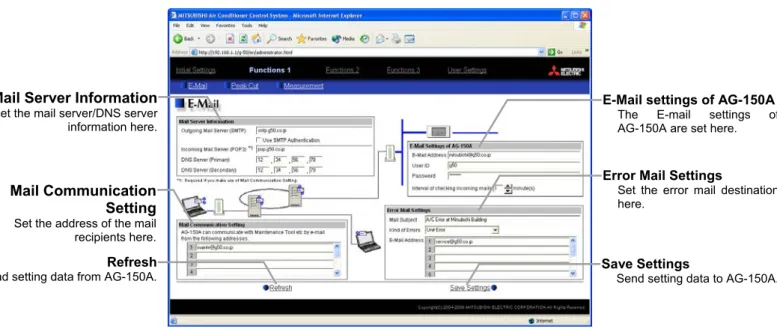
Click on [Functions 1] – [E-Mail] in the menu to open the [E-mail] window and make necessary settings to perform remote monitoring via mail, using error mail report or the maintenance tool.
Click [Save Settings] to send setting data to the AG-150A.
Note: The use of the error mail report function requires a separate license registration.
Confirm on the license registration screen (Ch8) that the license registration has been completed.
Note: If the user logs in as a building manager, the operations may be prohibited.
5-1-1 Entering the E-Mail Information for the AG-150A
Enter the E-mail information provided by either the ISP or the LAN administrator.
Note: When sending E-mail via an ISP, a user contract with the ISP is required.
Make necessary settings based on the functions that are to be used, using the table below as a reference.
Table 5-1 Items that Require Settings to Be Made (E-Mail Settings of AG-150A)
Error Mail Report Mail Communication
Functions
Items No SMTP
Authentication Uses SMTP
Authentication No SMTP
Authentication Uses SMTP Authentication
Mail Address V V V V
User ID V V V
Password V V V
Interval of checking incoming
mails V V
Save Settings
Send setting data to AG-150A.
Refresh Read setting data from AG-150A.
E-Mail settings of AG-150A The E-mail settings of AG-150A are set here.
Mail Server Information
Set the mail server/DNS server information here.
Mail Communication Setting
Set the address of the mail recipients here.
Error Mail Settings
Set the error mail destination here.
5-1-2 Setting the Mail Server Information
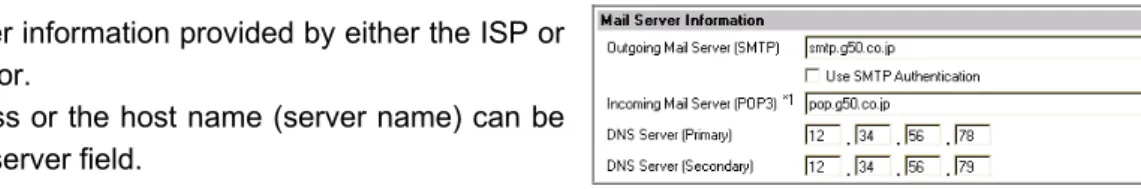
Enter the mail server information provided by either the ISP or the LAN administrator.
Either the IP address or the host name (server name) can be entered in the mail server field.
Make necessary settings depending on the functions to be used, using the table below as a reference.
Table 5-2 Items that Require Settings to Be Made (Mail Server Information)
Error Mail Report Mail Communication
Functions
Items No SMTP
Authentication Uses SMTP
Authentication No SMTP
Authentication Uses SMTP Authentication Outgoing Mail Server (SMTP) V
IP Address or Host Name
Host Name V
IP Address or V Host Name
Host Name V
SMTP Authentication V V
Incoming Mail Server (POP3) V
IP Address or Host Name
IP Address or V Host Name
DNS Server (Primary) (V)*1 V (V)*1 V
DNS Server (Secondary) (V)*1 V (V)*1 V
*1: Not necessary if the IP address is used as the mail server address.
5-1-3 Setting the Error Mail Destinations
(1) Enter the title of the error mail that will be sent from AG-150A in the [Mail Title] field. The title may contain a maximum of 40 characters.
Note: The following characters cannot be used in the mail title:
< > & “ ‘
(2) Choose the error type out of the following: [Unit Error], [Preliminary Unit Error], [Communication Error], [General Equipment] and [User Setting 1] through [User Setting 6]. Then enter the mail address of the recipient of the error mail.
(3) To send error messages only upon occurrences of certain errors, click the User Setting button that appear when "User Setting 1" through "User Setting 6" are selected, and register the error codes to be reported in the user settings.
A maximum of 20 error codes can be set for each user setting. In addition to specific error codes such as [1302] or [6607], codes such as [10**] or [12**] can also be used. If [10**] is set, for example, error mail will be sent upon an occurrence of any type of errors between [1000] and [1099].
If error codes are set on this screen, confirm that the address of the recipient is registered.
(4) To e-mail an error when an error occurs on general equipment connected to PLC for general equipment, click the PLC Connection button, which appears at the time of selection of "General Equipment", to set the IP address of PLC for general equipment.
The row number of the set IP address will be in an error mail as a PLC number. (Eg. When an error occurs on the No.20 PLC for general equipment that is in the second row, "PLC2-20" will be displayed on the error source
Note: TG-2000A is necessary to monitor the status of general equipment.
5-1-4 Setting the Addresses of the Recipient
To monitor and operate the unit with the maintenance tool via mail from a remote location, enter the mail address of the receiver in the [Mail Communication Setting].
A maximum of 10 addresses can be registered.
E-mail communication is possible only with the recipients whose addresses are registered on this screen.
5-1-5 Mail format
Error mails are sent in the format shown below.
Item Format Remarks
Mail title Set title Refer to 5-1-3 (1) for the setting of mail title.
From AG-150A unit name and unit ID Refer to 4-2-1 for the setting of AG-150A unit name and unit ID.
Date dd/MM/yyyy hh:mm:ss Date of error
Note: The date format set in section 4-2-4 will be applied.
Error unit
When an error occurs on air conditioners and general equipment
- M-NET address of the error source
Note: If an expansion controller is connected, the unit in error will appear in the [Expansion controller No. (1-3)]-[M-NET address] format.
When an error occurs on general equipment that is connected to PLC for general equipment
- PLC number (1 to 20) + connection number of general equipment (1 to 32)
When a communication error occurs on PLC for general equipment
- PLC number (1 to 20)
PLC number indicates the row number on the setting screen shown in 5-1-3 (4).
Note: When an error occurs on the general equipment that is connected via DIDO controller, M-NET address of the DIDO controller will be sent. (which means an error occurs on one of the general equipment that is connected to the DIDO controller)
When an error occurs on air conditioners From:Mitsubishi Building(000001)
Date:11/09/2005 16:32:12 Error unit:065
Error code:1302 Status:Occurrence
5-2 Energy-Save Control and Peak Cut Control
Click on [Functions 1] – [Peak Cut] in the menu to bring up the peak cut control screen, and make necessary peak cut settings to use the energy-save or peak cut control function.
Click [Save Settings] to send setting data to the AG-150A.
Note: Run the test run mode, and check that the equipment related to peak cut is connected properly to perform peak cut control.
(It is possible to perform control compulsorily by changing the control level.)
Note: The use of energy-save/peak cut control functions requires a separate license registration.
Confirm on the license registration screen (Ch8) that the license registration has been completed.
Note: If the user logs in as a building manager, some of the operations may be prohibited.
To enable peak cut, register the "Energy Saving (Peak Cut)" license to all AG-150A, and set the peak cut method and the indoor/outdoor units control methods. When the license is registered, the control can be performed in 5 degrees (Level 0-4).
To enable energy saving control at the constant rate, register the "Energy Saving" license to all AG-150A, and set the level to "0" in [Indoor/Outdoor unit control method] section.
Save Settings
Send setting data to AG-150A and PLC.
Refresh Read setting data from AG-150A and PLC.
Peak cut method Select the peak cut method.
Setting details
Set the details of the selected method.
Indoor unit control method Set the indoor unit control method.
Outdoor unit control method Set the outdoor unit control method.
AG-150A
Demand Controller Method
PI Controller
Up to 3 AG-150A can be connected.
Up to 10 AG-150A can be connected.
PLC (with Electric
Amount Count Software) Pulse-method watt-hour meter
AG-150A
Pulse Electric Amount Count PLC Method Demand level
report
PLC (with demand
input Software) Demand
Controller Demand level
contact input
Pulse
Pulse Notify the
control level
PLC etc PI Controller Method
AG-150A
From external system Method
Remote AG-150A Method
Pulse-method watt-hour meter Pulse-method
watt-hour meter
Monitors electric power
Monitors electric power
Monitors control level AG-150A
Expansion controller system selection buttons
Click to select the system to be set.
5-2-1 When Demand Controller Method is used
(1) To use Demand Controller Method, before using the PLC Software for demand input or Electric Amount Count Software, click on the PLC initialize button once to initialize the internal memory.
Note: Do not initialize the memory after the operation has begun, for it will clear all operation data.
(2) Enter the IP address for the PLC software for demand input.
(3) Enter the IP address of the AG-150A to which the demand levels are reported. A maximum of 10 addresses can be registered.
(4) When the energy-save level is set to 0 (It is always set to level 0 in an energy-save control method), energy-save control will not be performed for the indoor units that show a greater difference between the set temperature and indoor temperature than the value set in the window on the right.
Make the setting when some type of energy-saving control is effective at energy-save level 0 and the level of comfort is high on priority list. (Choose between 3 to 9)
5-2-2 When Electric Amount Count PLC Method (Amount Count Software) is used
(1) To use Electric Amount Count PLC Method, before using the PLC Software for demand input or Electric Amount Count Software, click on the PLC initialize button once to initialize the internal memory.
Note: Do not initialize the memory after the operation has begun, for it will clear all operation data.
(2) Enter the IP address of the electric amount count software.
(3) Select the terminal number of the DI board to which the watt-hour meter is connected. If it is connected to terminal 2 on DI board 1, select 1-2.
Note: Select an input board from either 1 or 2, and select an input terminal from 0 to F. Choose the terminal to which the watt-hour meter is connected that is used for peak cut.
(4) Enter the unit of the pulse that the watt-hour meter outputs.
(5) Determine the range of electricity use for each control level (demand level), taking into consideration such factors as delayed control of the air conditioner. Enter the value that is 10 to 15% below the maximum demand value (average electric energy value in 30 minutes) in the blank next to Level 4. Decrease the value by about 10 % for each level below. (The figure on the right shows the system with the maximum electric energy at 200 kW.)
Note: The best set point depends on the system configuration of the electric equipment and the indoor environment in each building. Choose appropriate set points accordingly.
Note: The amount of electricity that is actually used may exceed the demand value due to such unexpected incidents as controller problems or broken transmission lines. Mitsubishi will not be responsible for such incidents.
Note: Set the value per pulse according to the measurement meter to be used. To check that the setting is correctly made, first check both the values measured by the measurement meter and by the measurement controller, and after a certain time, check that the both values have increased at equal increments. (The value measured by the measurement controller can be checked on the browser for the administrator.)
5-2-3 When PI Controller Method is used
(1) Select the PI controller to which the watt-hour meter used for peak cut control is connected.
Note: Only the watt-hour meters that have been registered on the Measurement screen can be selected.
(2) Determine the range of electricity use for each control level (demand level), taking into consideration such factors as delayed control of the air conditioner. Enter the value that is 10 to 15% below the maximum demand value (average electric energy value in 30 minutes) in the blank next to Level 4. Decrease the value by about 10 % for each level below. (The figure on the right shows the system with the maximum electric energy at 200 kW.)
Note: The best set point depends on the system configuration of the electric equipment and the indoor environment in each building. Choose appropriate set points accordingly.
Note: The amount of electricity that is actually used may exceed the demand value due to such unexpected incidents as controller problems or broken transmission lines. Mitsubishi will not be responsible for such incidents.
(3) When the energy-save level is set to 0 (It is always set to level 0 in an energy-save control method), energy-save control will not be performed for the indoor units that show a greater difference between the set temperature and indoor temperature than the value set in the window on the right.
Make the setting when some type of energy-saving control is effective at energy-save level 0 and the level of comfort is high on priority list. (Choose between 3 to 9)
5-2-4 When Remote AG-150A Method is used
(1) Enter the IP address of the G-50 to which the PI controller (with the connection to the watt-hour meter used for peak cut control) is connected.
Note: As the control level of G-50 to which the watt-hour meter is connected is monitored every minute, the control level changes after a delay of approx. one minute. Take this delay into consideration, and set the control level without exceeding the range of peak cut electricity.
Note: Only up to three G-50 can be connected to the G-50 to which the watt-hour meter is connected. When five or more AG-150A are used in a system, use electric amount count PLC method mentioned in 5-2-2.
(2) When the energy-save level is set to 0 (It is always set to level 0 in an energy-save control method), energy-save control will not be performed for the indoor units that show a greater difference between the set temperature and indoor temperature than the value set in the window on the right.
Make the setting when some type of energy-saving control is effective at energy-save level 0 and the level of comfort is high on priority list. (Choose between 3 to 9)
5-2-5 When From external system Method is used
(1) When the energy-save level is set to 0 (It is always set to level 0 in an energy-save control method), energy-save control will not be performed for the indoor units that show a greater difference between the set temperature and indoor temperature than the value set in the window on the right.
Make the setting when some type of energy-saving control is effective at energy-save level 0 and the level of comfort is high on priority list. (Choose between 3 to 9)
5-2-6 Setting the Outdoor Unit Control Method (All methods)
Make the energy-save control setting for the outdoor units for each energy-save level.
Note: M-NET addresses are displayed on outdoor units of City multi type. M-NET addresses and group names are displayed on A-control units (Slim units).
Note: As for A-control outdoor units, only the inverter models can be put on the energy save control. Do not make the energy save settings for the constant speed models.
(1) Set the maximum operating capacity at each level.
Normally, outdoor units operate at 100% capacity.
The smaller the maximum operating capacity, the more energy will be saved.
Note: Energy-saving effects cannot be expected when the outdoor units are running with low load and are operating below the set capacity level.
Note: Do not use the capacity-save control with heat-accumulating units (ICE-Y) or Multi S units. On these units, always set the capacity to “100%.”
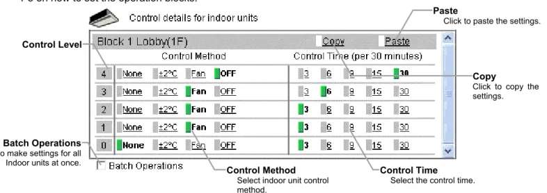
(2) Set the control time at each level. When a capacity-save control over outdoor units is performed, it is recommended that the control time be set to either 30 or 15 minutes, for shorter control time is not likely to bring much benefit.
If any time other than “30-minute” is selected, the control is done on rotation so as to avoid the overlapping
Click to copy the settings.Copy
Paste Click to paste
the settings.
Batch Operations Used to make settings for all
outdoor units at once.
Control Level
Control Time Select the control time.
Maximum Capacity
Select the upper limit of outdoor unit operating capacity.
Capacity
80%
Maximum Capacity at 80%
Capacity Value
No energy-saving effects
Amount of saved energy
With energy-saving effects Time
Expansion controller system selection buttons
Click to select the system to be set.