For the repair of cooling systems, (1-3) through (1-7) must be performed before working on the systems. When electrical components are replaced, they must be fit for purpose and to the correct specifications. This should be reported to the owner of the device so that all parties can be advised.
When breaking into the cooling circuit to carry out repairs – or for any other purpose – conventional procedures must be used. Before recharging the system, it must be pressure tested with the appropriate purge gas. The equipment must be marked as having been taken out of service and emptied of refrigerant.
In addition, a set of calibrated scales should be available and in good working order. The recovered refrigerant will be returned to the refrigerant supplier in the appropriate recovery cylinder and the appropriate waste transfer note will be adjusted. The evacuation process must be carried out before returning the compressor to the suppliers.
To accelerate this process, only electric heating of the compressor body is used.
7 WIRING DIAGRAM
REFRIGERANT SYSTEM DIAGRAM8
INDOOR UNIT
OBH801
9 SERVICE FUNCTIONS
9-1. TIMER SHORT MODE
9-2. HOW TO SET REMOTE CONTROLLER EXCLUSIVELY FOR A PARTICULAR INDOOR UNIT A maximum of 4 indoor units with wireless remote controllers can be used in a room
How to set the remote controller
How to modify the electronic control P.C. board
The operation settings are memorized when 10 seconds have passed after the indoor unit is operated by the remote controller. If the unit was turned off with the remote control before the power failure, the auto restart function will not work because the power button of the remote control is disabled. To prevent the circuit breaker from tripping due to the power surge, systematize other household appliances so as not to turn on at the same time.
When some air conditioners are connected to the same supply system, the starting current for all the compressors can flow simultaneously on restart if they are operating before the power failure. Therefore, the special countermeasures are required to prevent the main voltage drop or rush of starting current by adding to the system that allows the units to start one by one.
How to disable “AUTO RESTART FUNCTION”
If the main power is turned OFF or there is a power failure while the AUTO START/STOP timer is active, the timer setting is canceled. NOTE: When the ceiling is higher than 2.7m, the airflow may be insufficient even if the Dip switch (SW3) is set to "increase airflow". Setting when lower air flow is preferred in the direction of air flow (1) The angle of the air flow direction (1) can be slightly lowered by changing SWV1 to normal when lower air flow is preferred or if the air flow causes dirt on the ceiling.
MLZ-KP25VF MLZ-KP35VF MLZ-KP50VF WIRELESS REMOTE CONTROL WIRELESS REMOTE CONTROL.
MICROPROCESSOR CONTROL10
INDOOR UNIT DISPLAY SECTION
10-1. COOL ( ) OPERATION
Coil frost prevention
10-2. DRY ( ) OPERATION
10-4. HEAT ( ) OPERATION
- Cold air prevention control
- Defrosting
- Float sensor
- Vertical vane
- How to set the time
- To release the timer
Other indoor units cannot operate and the operation indicator lamp flashes as shown in the figure below. In heating operation, although the indoor unit that is not working may be warm or the sound of refrigerant leakage may be heard, they are not malfunctioning. The direction of rotation, speed and angle of the motor are controlled by pulse signals (approximately 12 V) transmitted by the internal microprocessor. 2) The horizontal vane angle and mode are changed as follows by pressing the VANE CONTROL button.
The airflow direction (1) can be slightly reduced by setting SWV1 to normal when a lower airflow is preferred or when the airflow causes dirt on the ceiling. Confirmation of the default position is performed in the following cases:. a) When the power is turned on. In the following cases, the horizontal vane returns to the closed position. a) When the STOP/OPERATE button is pressed (OFF).
In VANE AUTO mode, the microprocessor automatically determines the vane angle and operation for optimal room temperature distribution. Confirmation of the standard position is carried out in the following cases:. a) When the STOP/OPERATE(OFF/ON) button is pressed. At first, the current time display on the TIME MONITOR flashes “0:00”, so set the current time correctly with the CLOCK SET button.
How to set the current time (a) Press the CLOCK setting button. b) Press the TIME SET ( and ) buttons to set the current time. Each time the FORWARD button ( ) is pressed, the set time increases by 1 minute, and each time the BACKWARD button ( ) is pressed, the set time decreases by 1 minute. Set the time of the timer with the buttons TIME SET ( and ). a) Press the OFF TIMER ( ) button during operation.
Each time the FORWARD ( ) button is pressed, the set time increases by 10 minutes: each time the BACKWARD ( ) button is pressed, the set time decreases by 10 minutes.
PROGRAM TIMER
10-9. WEEKLY TIMER OPERATION
How to set the weekly timer
When the timer is set for more than one day of the week or one number, the button does not need to be pressed per each setting. Press button to enter weekly timer setting mode, and press and hold button for 5 seconds to clear all weekly timer settings. When the weekly timer is ON, the day of the week the timer setting is completed will light up.
Checking weekly timer setting Checking weekly timer setting
How to cancel operation
In case of test run or emergency operation, use the EMERGENCY OPERATION switch on the right side of the indoor unit. Emergency operation is available when the remote control is missing or defective, or the batteries in the remote control are running low. In the test run or emergency operation, the horizontal vane operates in VANE AUTO mode ( ).
Emergency operation continues until the EMERGENCY switch is pressed once or twice or until the unit receives a signal from the remote control. When the system shuts down, the compressor will not restart for 3 minutes because the 3-minute time delay function works to protect the compressor from overloading.
TROUBLESHOOTING11
Take care of the following during servicing
Troubleshooting procedure
How to replace batteries
11-2. FAILURE MODE RECALL FUNCTION Outline of the function
Flow chart of failure mode recall function for the indoor/outdoor unit
Flow chart of the detailed outdoor unit failure mode recall function
Indoor unit failure mode table
If the blinking of the OPERATION INDICATOR lamp cannot be verified, it can be verified with the failure mode recall function.
11-3. INSTRUCTION OF TROUBLESHOOTING
NOTE: When the indoor unit has started operation and the above-mentioned faults are detected (the first detection after power-up), the indoor electronic control P.C. When the serial signal from the outdoor unit is not received for up to 6 minutes. When the data in the non-volatile memory of the electronic indoor control P.C.
11-4. TROUBLESHOOTING CHECK TABLE
The compressor stops 3 times in succession due to over current protection or start failure protection within 1 minute after starting. When the operation mode of each indoor unit is otherwise set to COOL (including DRY) and HEATING at the same time, the operation mode of the indoor unit that operated first takes precedence.
11-5. TROUBLE JUDGEMENT CRITERIA OF MAIN PARTS
Check of indoor fan motor A
11-6. TROUBLESHOOTING FLOW
The indoor unit works by pressing the EMERGENCY OPERATION key, but does not work with the remote control. Turn on an AM radio and press the STOP/OPERATE (OFF/ON) button on the remote control. Are there inverter-type or fast-flashing fluorescent lights within 1 m.
1 Look at the image of the signal transmitting part of the remote control through the screen of a digital camera or camera phone. It is normal if the LED in the signal transfer section lights up when STOP/. However, it may be difficult to see the illuminated LED in the signal transfer section with a smartphone camera.
2 If the fluorescent light of the inverter is on when the room is cold, the unit may have trouble receiving the signal from the remote control or may not be able to operate it; if the inverter fluorescent light is on when the room is warm, the unit may be able to operate with the remote control.
Check of indoor electronic control P.C. board and indoor fan motor C
When the left lamp of the OPERATION INDICATOR lamp turns on and off every 0.5 seconds. Is there any misconnection, poor contact or wire disconnection of the indoor/outdoor connecting wire.
Check of float sensor E
Yes Whether the distance between the antennas and the indoor unit is within 3m or the distance between the antennas and the outdoor unit is within 3m. Increase the distance between the antennas and the indoor unit and/or the antenna and the outdoor unit. Is the distance between the TV or radio and the indoor unit within 1m or is the distance between the TV or radio and the outdoor unit within 3m.
Extend the distance between the indoor/outdoor connection wire of the air conditioner and the wires of the antennas. Even if all the above conditions are met, the electromagnetic noise may penetrate depending on the strength of the electric field or the installation condition (combination of specific conditions such as antennas or wiring).
11-7. TEST POINT DIAGRAM AND VOLTAGE
Indoor electronic control P.C. board
OPERATING PROCEDURE PHOTOS/FIGURES
Removing the intake grille
DISASSEMBLY INSTRUCTIONS12
Removing the grille (1) Remove the intake grille
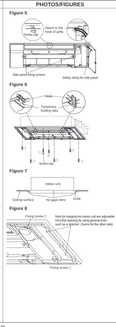
NOTE: Make sure the tabs on the side panels fit securely in place (Figure 9). NOTE: Make sure there are no gaps between the emergency operation switch and the side panel (Figure 10). NOTE: Make sure the safety strings are not hanging out of the side panels.
NOTE: Press the intake grille firmly against the grille until a click is heard from each tab on the left and right sides.
Removing the heat exchanger and stabilizer (1) Remove the grille
Removing the horizontal and vertical vane motors
Removing the drain pump and float sensor (1) Remove the grille
Removing the fan motor and line flow fan (1) Remove the grille